Table of Contents
Advertisement
Advertisement
Table of Contents

Summary of Contents for Atlas-Lift PRO-9D
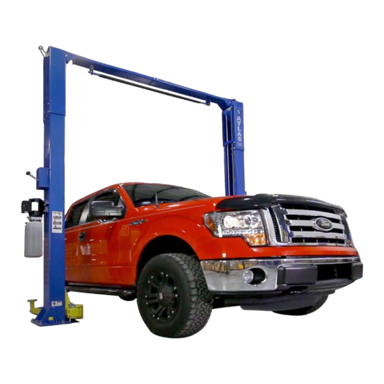
- Page 1 9,000 POUND TWO-COLUMN AUTOMOTIVE LIFT Model: PRO-9D MANUAL ATLAS-Lift...
-
Page 2: Table Of Contents
Table of Contents WARRANTY..............................2 PRO-9D Definition............................3 PRO-9D Important Notes...........................3 PRO-9D BASIC SPECIFICATION......................4 PRO-9D NINE TWO POST LIFT......................4 IMPORTANT FOUNDATION AND ANCHORING INFORMATION............ 5 ANCHORING TIP SHEET......................... 6 PREPARATION............................6 GENERAL INFORMATION........................7 RAISE LIFT............................10 LOWER LIFT............................10 SAFETY PROCEDURES........................ - Page 3 9,000 POUND CAPACITY MODEL: PRO-9D TWO-COLUMN AUTOMOTIVE LIFT READ THIS ENTIRE MANUAL BEFORE OPERATION BEGINS RECORD BELOW THE FOLLOWING INFORMATION WHICH IS LOCATED ON THE SERIAL NUMBER DATA PLATE Serial No. Model No. Date of Install RECORD BELOW THE FOLLOWING CUSTOMER INFORMATION...
-
Page 4: Warranty
WARRANTY The structural components on your new automotive lift are warranted for five years on equipment. Operating components are warranted one year to the original purchaser, to be free of defects in material and workmanship. The manufacturer shall repair or replace at their option for this period those parts returned to the factory freight prepaid which prove after inspection to be defective. -
Page 5: Pro-9D Definition
PRO-9D Important Notes Please read the Safety Procedures and operation instructions in this manual before operating the lift. Proper installation is very important. To minimize the chance of making an error in installation, please read this manual through carefully before beginning installation. -
Page 7: Important Foundation And Anchoring Information
IMPORTANT FOUNDATION AND ANCHORING INFORMATION Concrete shall have compression strength of at least 3,000 PSI and a minimum thickness of 4” in order to achieve a minimum anchor embedment of 3 ¼”. When using the standard supplied ¾” x 5 ½” long anchors;... -
Page 8: Anchoring Tip Sheet
ANCHORING TIP SHEET 1. Anchors must be at least 6" from the edge of the slab or any seam. 2. Use a concrete hammer drill with a carbide tip, solid drill bit the same diameter as the anchor, 3/4". (.775 to .787 inches diameter). Do not use excessively worn bits or bits which have been incorrectly sharpened. -
Page 9: General Information
GENERAL INFORMATION 1. Any freight damage must be noted on the freight bill before signing and reported to the freight carrier with a freight claim established. Identify the components and check for shortages. If shortages are discovered, contact Hanmecson International, Inc. immediately. 2. - Page 10 underneath the base plate and around the anchor bolt. This will prevent bending the column bottom plates (Shim thickness should not exceed ½”). Tighten ¾” anchor bolts to 150 ft-lbs. of torque. STEP 8: Using a tape measure, measure from back corner of the base to the opposite back corner to insure legs are square.
- Page 11 right column carriage nut adjusts the left column carriage. Adjust each cable to approximately 1/2" side-to-side play. Check the latch releases to insure the carriage is still engaged in the appropriate latch. STEP 15: Install all four swing arms, readjust the arm lock preinstalled to make sure that gear rack are engaging the moon gear on the arm properly.
-
Page 12: Raise Lift
RAISE LIFT Press button on power unit The safety latch mechanism will 'trip over' when the lift raises and drop into each latch stop. To lock the lift you must press the Lower lever to relieve the hydraulic pressure and let the latch set tight in a lock position. Note: It is normal for an empty lift to lower slowly - it may be necessary to add weight. -
Page 13: Safety Procedures
SAFETY PROCEDURES Never allow unauthorized persons to operate lift. Thoroughly train new employees in the use and care of lift. Caution - the power unit operates at high pressure. Remove passengers before raising vehicle. Prohibit unauthorized persons from being in shop area while lift is in use. ... -
Page 14: Maintenance Schedule
MAINTENANCE SCHEDULE The following periodic maintenance is the suggested minimum requirements and minimum intervals; accumulated hours or monthly period, which ever comes sooner. If you hear a noise not associated with normal lift operation, or, if there is any indication of impending lift failure - CEASE OPERATION IMMEDIATELY! - inspect, correct and/or replace parts as required. -
Page 15: Weekly Maintenance (40 Hours)
WEEKLY MAINTENANCE (40 HOURS) Check anchor bolts torque to 150 ft-lbs for the ¾” anchor bolts. Do not use impact wrench. Check floor for stress cracks near anchor bolts Check hydraulic oil level. Check and tighten bolts, nuts, and screws. ... -
Page 16: Troubleshooting
TROUBLESHOOTING Motor does not operate Breaker or fuse blown. Motor thermal overload tripped. Wait for overload to cool. Faulty wiring connections; call electrician. Defective up button call electrician for checking. Motor functions but lift will not rise A piece of trash is under check valve. Push handle down and push the up button at the same time. -
Page 17: Owner / Employer Responsibilties
OWNER / EMPLOYER RESPONSIBILTIES The Owner / Employer: Shall established procedures to periodically maintain, inspect and care for the lift in accordance with the manufactures recommended procedures to ensure its’ continued safe operations. Shall provide necessary lockout / tagouts of energy sources per ANSI Z244.1 – 1982 before beginning any lift repairs.
Need help?
Do you have a question about the PRO-9D and is the answer not in the manual?
Questions and answers