Advertisement
Quick Links
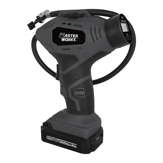
MODEL: MW110D
20V
20V AUTOMATIC CORDLESS INFLATOR
Operator's Manual
SAVE THIS MANUAL
You will need this manual for safety instructions, operating procedures and warranty.
Put it and the original sales receipt in a safe dry place for future reference If you
have a question or experience a problem with your purchase, please contact
us via E-mail service@masterworkstool.com or call 1-866-458-2320.
Advertisement

Summary of Contents for Master WORKS MW110D
- Page 1 MODEL: MW110D 20V AUTOMATIC CORDLESS INFLATOR Operator’s Manual SAVE THIS MANUAL You will need this manual for safety instructions, operating procedures and warranty. Put it and the original sales receipt in a safe dry place for future reference If you have a question or experience a problem with your purchase, please contact us via E-mail service@masterworkstool.com or call 1-866-458-2320.
-
Page 2: Table Of Contents
TABLE OF CONTENTS ■ IMPORTANT SAFETY INSTRUCTIONS---------------------------------------------------------------P.2 ■ SAFETY PRECAUTIONS FOR INFLATOR-----------------------------------------------------------P.3 ■ SPECIFICATIONS -------------------------------------------------------------------------------------------P.4 ■ FUNCTIONAL DESCRIPTION----------------------------------------------------------------------------P.5 ■ OPERATION---------------------------------------------------------------------------------------------------P.6 ■ MAINTENANCE ----------------------------------------------------------------------------------------------P.9 ■ PARTS LIST AND SCHEMATIC DRAWING----------------------------------------------------------P.10 IMPORTANT SAFETY INSTRUCTIONS WARNING: READ AND UNDERSTAND ALL INSTRUCTIONS. Failure to follow all instructions listed below, may result in electric shock, fire and/or serious personal injury. -
Page 3: Safety Precautions For Inflator
IMPORTANT SAFETY INSTRUCTIONS INFLATOR USE AND CARE 1. Check hoses for weak or worn condition before each use, making certain all connections are secure. Do not use if defect is found. Purchase a new hose or notify an authorized service center for examination or repair. -
Page 4: Specifications
SAFETY PRECAUTIONS FOR INFLATOR 10. Always disconnect the air supply and power supply before making adjustments, servicing an inflator, or when an inflator is not in use. 11. Do not attempt to pull or carry the inflator by the hoses. 12. -
Page 5: Functional Description
FUNCTIONAL DESCRIPTION A. Rubber-covered handle B. Air hose C. Air chuck D. Digital pressure gauge E. Hose storage area F. Battery G. Start switch H. Self-Locking switch I. 12V Power adapter J. LED-light K. Battery indicator L. USB Output Port... -
Page 6: Operation
OPERATION BATTERY PACK WARNING: The battery is not fully charged. efore first use, the battery pack requires 5-7 hours charging time to be fully charged. Subsequent recharging needs 3-5 hours for the battery to be fully charged. Always switch to a fresh battery when tool performance begins to diminish. Severe heat is most destructive to a battery;... - Page 7 OPERATION 5V USB OUTPUT CHARGING 1.Plug the device USB cable into the USB Output Port (A) on the battery Pack (Fig.2) 2.Press the button (B) for charging (Fig.3) WARNING: Do not allow familiarity with this product to make you careless. Remember that a careless fraction of a second is sufficient to inflict serious injury.
- Page 8 OPERATION Connecting and removing the battery 12 V car plug-in power base 1. Unravel cord before use . If battery is installed, remove from the machine by pressing battery release button and pulling out 2. Slide the 12V DC Car Adapter pack into the machine until you hear a click. 3.
-
Page 9: Maintenance
OPERATION A- Air chuck clamp in B - Air chuck clamp in unlocked position locked position C - Valve stem D - Air chuck E -Air hose F - Air chuck clamp NOTICE: Always leave the hose free of obstructions when the tool is not in use. Overheating could occur if the hose is blocked. -
Page 10: Parts List And Schematic Drawing
PARTS LIST AND SCHEMATIC DRAWING DESCRIPTION DESCRIPTION Left housing Right housing Absorber Screw Digital gauge Screw Air pump assembly LED cover Microswitch Red wire 1 Trigger LED light Spring Red wire 2 Black wire Motor Torsional spring Batter clip assembly Battery Pack Self-locked switch...
Need help?
Do you have a question about the MW110D and is the answer not in the manual?
Questions and answers