
Summary of Contents for Dynablast HV700F
- Page 1 Operating manual last Dynab Division of John Brooks Company Limited 2625 Meadowpine Blvd, Mississauga, Ontario L5N 7K5 Ontario/Quebec/Maritimes Tel: 888-881-6667 Alberta/Manitoba/Sask/B.C. Tel: 800-527-8592 www.dynablast.ca 4/19 rev 2...
-
Page 2: Table Of Contents
Table of Contents Safety Considerations and Warnings Pre-operating Instructions Connecting Operating instructions / Burner Setup Operating Instructions Maintenance 9-10 Specifications Troubleshooting 12-15 Warranty policy Service Bulletin Illustrated Parts List 18-27 Electrical wiring diagram... -
Page 3: Safety Considerations And Warnings
SAFETY CONSIDERATIONS AND WARNINGS Please read this manual completely before installing or operating your Dynablast pressure washer or steam cleaner. Professional Service Required: Incorrect installation or misuse of this equipment could result in server personal injury or death from heavy smoke, fire or explosion. -
Page 4: Pre-Operating Instructions
PRE-OPERATING INSTRUCTIONS Arrange with a qualified electrician to install a properly grounded, if negative & positive power wires lengths are extended increase gauge size of wire. Protect the receptacle from splashes, the recommended high above the ground is a minimum four feet, or as recommended by the local code. -
Page 5: Connecting Operating Instructions / Burner Setup
Remote piping If you are installing permanent piping runs from your Dynablast unit to remote wash locations, use only Schedule 80 pipe and heavy duty fittings rated for the operating pressure of your pumping module or use pressure or steam rated reinforced flexible hose suitable for the operating pressure. - Page 6 Fuel hook up HV700F / HV900F Supply line connection Return line If the heater module will be mounted in a remote service vehicle, it must be mounted to a ridged part of the frame to ensure adequate support. Keep in mind the heat exchanger coil is very heavy with a great deal of mass towards to top of the coil.
-
Page 7: Operating Instructions
Fuel supply: The supply of fuel for the burner should be uninterupted, or continous. This burner uses a 2 fuel line system, (supply and return). The supply and return lines are to be as short and direct as possible limiting the vertical suction lift (also consider the fuel level of the tank will drop over time). - Page 8 Be sure water can flow to the heater coil before turning on burner switch. Start the pumping unit involved until a steady stream of water is flowing from the spray gun (holding the spray gun open. Turn burner switch to “ON” position. Burner will ignite and remain in operation as long as there is sufficient water flow to satisfy the flow switch and temperature limit control.
- Page 9 Before adjusting the machine to produce steam output, remove the pressure washer trigger gun/wand and install the open steam clean wand. After installing the steam wand and Hose, turn the pressure adjustment control down to 350 psi. Using the steam wand with the pressure turned down to 350 psi reduces the volume of water flowing through the heater coil thereby raising the outlet temperature from the coil.
-
Page 10: Maintenance
Caution: DO NOT attempt to start the burner when excess fuel has accumulated, or when the heat exchanger coil is full of vapors, or when the combustion chamber is hot. Vapor-Filled combustion chamber: Allow the unit to cool off and all vapors to dissipate before attempting an- other start Oil flooded combustion Chamber: Shut off the electrical power and the oil supply to the burner, then clear all accumulated oil before continuing... - Page 11 Most pressure wash applications are made easier to perform by using the outlet device that best suits the task at hand. The list below summarizes the most common types of outlet devices - consult with your Dynablast dealer for more information.
-
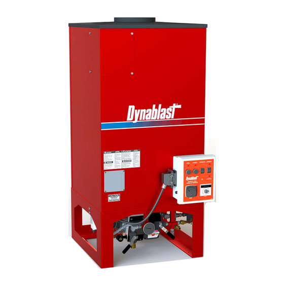
Page 12: Specifications
26.5 x 26.5 x 58 26.5 x 26.5 x 64 WEIGHT (LBS) COIL 3/4" SCH 80 PIPE 3/4" SCH 80 PIPE Initial factory settings: HV700F Air band ½ open HV900F Air band 5 Air shutter 9 Air Band Position Indicator Air Shutter Position Indicator... -
Page 13: Troubleshooting
Troubleshooting Guide WARNING: POTENTIAL FOR FIRE, SMOKE AND ASPHYXIATION HAZARDS Repairs or adjustments to the burner must ONLY be carried out by a professional, qualified oil fired burner Technician. Incorrect installation, adjustment or misuse of this burner could result in death, severe personal injury, or substantial property damage. - Page 14 Frozen coil Repair or Replace. Broken fitting(s) Replace. Severe condensation Check insulation on bottom and around coil. Repair any tears or gaps in insulation. Burner runs but does not Air band open too much or too Adjust air band run smooth little Fuel filter/fuel connections Tighten or repair...
- Page 15 Beckett CF800 / Wayne EH Oil Burner with integrated Controller Refer to Beckett & Wayne owner’s manual. Getting to know your 120V primary control...
- Page 16 Refer to Beckett & Wayne owner’s manual.
-
Page 17: Warranty Policy
(but keep a copy for your files). DYNABLAST INC. liability under warranty is limited to repair of the product and/or replacement of parts and is given to the purchaser in lieu of all other remedies including incidental and collateral charges. There are no expressed warranties other than those specified herein. -
Page 19: Illustrated Parts List
Parts Breakdown HV700F... - Page 20 Parts Breakdown HV700F BURNER ASSEMBLY ITEM NUMBER PART NUMBER DESCRIPTION QUANTITY 1 HWHE31761-082 GUN ASSEMBLY 2 HW4.580B FUEL NOZZLE 3 HWHE13286 ELECTRODE KIT 4 HWHE21126 BURNER MOTOR 5 HWELBC52171-K 4X4X2 STEEL JUNCTION BOX 6 HWHER8184G1031 120V PRIMARY CONTROL 7 HWHE101295-SERE...
- Page 21 Parts Breakdown HV900F...
- Page 22 Parts Breakdown HV900F ITEM NO. PART NUMBER DESCRIPTION QTY. HWHEEPCF800 (EP1301) 900 BECKETT BURNER HWHE7505A0000U PRIMARY CONTROL 1/4 PUSH X 1/4MP ADAPTOR HWFI1725-4B 1/4 ID FUEL LINE HWEP80057 18" RACOR FUEL FILTER HWFIA-25A 1/4 X 1/4 HEX NIPPLE HWFIS1022-B HWEP24456 FUEL FILTER BRACKET HWFI116-B-PH 1/4"...
- Page 23 Parts Breakdown HV700F / HV900F Ref No Part Number Description Quantity HWHEQ80753 82" X 24" X 1" 607 BLKT HW40209 700 Coil HW40210 900 Coil HWEP27167 Bottom Steel Ring HWHEQ80752 Bottom Insulation Ring HW40209KIT INSULATION KIT REQUIRED WITH COIL 700 or 900 REPLACEMENT...
- Page 24 Parts Breakdown HV700F / HV900F INLET Ref No. Part Number Description Quantity HWFIMP113-D5H 1/2" X 5" Steel Nipple HWFIS1002-D 1/2" ST Cross GP100984 12 GPM Relief Valve HWFIS1010-DC 3/8"F X 1/2"M Steel Bushing PSW1 Pressure Switch 3 Wire HWFIMP113-D41/2H 1/2" X 4.5" NIPPLE HWFIS1000-D 1/2"F X 1/2"F Steel Elbow...
- Page 25 Parts Breakdown HV700F / HV900F DISCHARGE Ref No. Part Number Description Quantity HWFIMP113-D6 1/2" X 6" Steel Nipple HWFIS1000-D 1/2" X 1/2" Steel Elbow HWFIS1022-D 1/2" X 1/2" Male Coupler HWFIS1001-D 1/2" ST Female Tee HWFI348-12D 1/2" To 3/4" JIC...
- Page 26 Parts Breakdown HV700F / HV900F...
- Page 27 Parts Breakdown HV700F / HV900F ELECTRICAL BOX ITEM NUMBER PART NUMBER DESCRIPTION QUANTITY HV120DP COMPLETE CONTROL BOX 1 HWELVJ1008SO CONTROL BOX WITH HOLES 2 Included with part # 7 CONTACT BLOCK 3 Included with part # 7 HOUSING 4 HWEP23394SO...
- Page 28 Parts Breakdown HV700F / HV900F Ref No. Part Number Description Quantity HWFIS1015-D 1/2" MF Elbow HWFIS1022-D 1/2" Hex Nipple HWEP24491 Steam Bracket (Cross) HWFI2809-12-48 Steam Hose HWFIS348-12D GIC Fitting HWFIS1001-D 1/2" Tee HWELATS7799-1IN Thermocouple Probe HWEP39504A Ball Valve HWEP22218 MP 1/2"...
-
Page 29: Electrical Wiring Diagram
HV700F / 900F W GP103011...
Need help?
Do you have a question about the HV700F and is the answer not in the manual?
Questions and answers