Advertisement
Models:
EBC-12 & EBC-24
Page 1 of 2
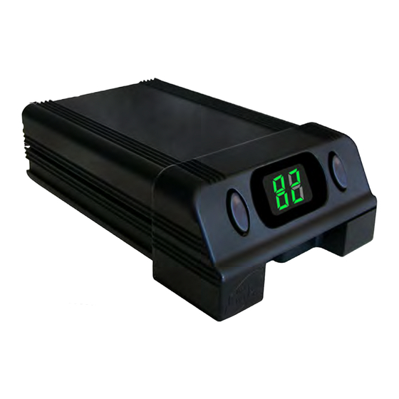
The EBC range is a new generation of brake controllers
utilising microprocessor based technology. It is a compact,
rugged, all electronic brake controller and is easily installed
with the connection of four wires and the mounting bracket
supplied. Easily adjustable via the front display and
simple up, down controls. Both models also incorporate
an emergency over-ride slide lever for manual control.
Designed for both single and dual axle trailers using
negative earth (ground) systems only. Available in 12V &
the new 24V version eliminating the need for a separate
reducer on 24V systems.
Note : The EBC-24 is load activated and can not be tested without load. At no load, output reading of 24V will register.
Pleas note that the output voltage is PULSED, so it cannot be measured with a volt meter or test light.
* The Control Unit is Activated by A Positive Feed Brake Switch Only.
(Please check the polarity of your vehicles brake switch before connection)
Features :
• Digital Display For Accurate Set-Up And Ease Of Use
• Easy adjustment Via Two Push-buttons
• Open circuit & Overload Indication and protection
• Convenient Over-Ride Slide Lever
Installation :
1. Disconnect the vehicle's NEGATIVE battery terminal.
2. Determine a suitable mounting location. The unit must be mounted securely to a solid surface and be easily accessible to the driver.
3. Hold the mounting bracket in the selected position and mark the hole location through the holes in the bracket.
4. Using a suitable drill bit, drill holes in the marked locations.
5. Secure bracket in position with self tapping screws being careful not to strip the holes by over-tightening.
6. Mount the brake control unit in the bracket by snapping into position.
White Wire: 0V DC
Blue Wire: Brake
Black Wire: +VDC
Red Wire: Brake Switch
* Please Note: An External Fuse Must Be Fitted (Not Supplied).
ELECTRONIC BRAKE CONTROLLER
Installation & Operating Instructions
Please read these instructions before use
Specifications
Minimum Input Voltage
Nominal Input Voltage
Maximum Input Voltage
Output Voltage
Suitable For 12V Trailer Brakes
No Current Load
Maximum Load
Dimensions
Weight
15A Fuse*
Unit 2, 1 St James Place, Seven Hills ,NSW, 2147, Australia
More information https://www.caravansplus.com.au
• Selectable Three Position Ramp-Up For Brake Speed
• 2 Axel 12A Output Capability
• Top Or bottom Mounting Via The Multi Position Bracket
• Can Be Mounted On Any Angle
EBC-12
EBC-24
9 VDC
18 VDC
12 VDC
24 VDC
15 VDC
30 VDC
12V
12V
Yes
Yes
30 mA
2 Axel / 12A Avg
40mm x 80mm x 125mm
270gm
EBC-R22
Advertisement
Table of Contents

Related Manuals for GSL electronics EBC-12

Summary of Contents for GSL electronics EBC-12
- Page 1 Models: ELECTRONIC BRAKE CONTROLLER EBC-12 & EBC-24 Page 1 of 2 Installation & Operating Instructions Please read these instructions before use Specifications The EBC range is a new generation of brake controllers EBC-12 EBC-24 Minimum Input Voltage utilising microprocessor based technology. It is a compact,...
- Page 2 Models: ELECTRONIC BRAKE CONTROLLER EBC-12 & EBC-24 Page 2 of 2 Installation & Operating Instructions Please read these instructions before use Wiring: Please ensure that a fuse is fitted in the Blue Wire (Brake). The Brake Controller has four (4) coloured wires, black, red, blue and white. The black wire is the positive voltage power supply line.
Need help?
Do you have a question about the EBC-12 and is the answer not in the manual?
Questions and answers