Table of Contents
Advertisement
WARNING: If the information in this manual
is not followed exactly, a fire or explosion
may result causing property damage, personal
injury or loss of life.
-
Do not store or use gasoline or other flammable
vapors and liquids in the vicinity of this or any
other appliance.
-
WHAT TO DO IF YOU SMELL GAS:
• Do not try to light any appliance.
• Do not touch any electrical switch; do not use
any phone in your building.
• Immediately call your gas supplier from a
neighbour's phone. Follow the gas supplier's
instructions.
• If you cannot reach your gas supplier, call the
fire department.
WARNING: Improper installation,
adjustment, alteration, service or
maintenance can cause injury
or property damage. Read the
installation, operating and maintenance
instructions thoroughly before installing
or servicing this equipment.
WARNING: For Outdoor Use Only
Advertisement
Table of Contents

Related Manuals for Gentherm P-5050

Summary of Contents for Gentherm P-5050
- Page 1 WARNING: If the information in this manual is not followed exactly, a fire or explosion may result causing property damage, personal injury or loss of life. Do not store or use gasoline or other flammable vapors and liquids in the vicinity of this or any other appliance.
- Page 2 AVERTISSEMENT: si l’information de ce man- uel n’est pas suivie exactement, un incendie ou une explosion peut resulter entraînant des dégâts matériaux, des blessures ou la perte de vie. Ne pas entreposer ou utiliser de l’essence, d’autres liquides ou vapeurs inflammables à proximité...
- Page 3 GLOBAL POWER TECHNOLOGIES P-5050 THERMOELECTRIC GENERATOR Operating Manual 62553 Rev 8 Gentherm Global Power Technologies Unit 16, 7875 - 57th Street SE Calgary, Alberta Canada, T2C 5K7 Phone: 1 (403) 236-5556 Fax: 1 (403) 236-5575 www.genthermglobalpower.com * * For latest version download from website NOTICE TO INSTALLER: These instructions shall be left with the consumer to retain them for future reference.
-
Page 5: Table Of Contents
4.1 Model P-5050 Thermoelectric Generator ........4-1... - Page 6 11.3 Model P-5050 Fuel System ......... . . 11-6 11.4 Model P-5050 Optional Steel Fuel System ....... 11-7 11.5 Model P-5050 Electrical...
- Page 7 Figure 1: Overall Dimensions of the P-5050 TEG ....... . .
-
Page 9: About This Manual
Power Unit (PU): The hermetically sealed portion of the TEG that contains the thermoelec- tric materials and cooling fins. Rated Power: Model P-5050 TEG produces 50 W when operating in an ambient tempera- ture of 20ºC (68ºF). With the fuel flow held constant TEGs operating in ambient tempera- tures higher than 20ºC (68ºF) will see power output efficiency reduce, 0.2 W per ºC (0.1... - Page 10 TEG. Solenoid Valve (SV): A electrically actuated valve that controls the gas supply to the burner. This Valve is operated by the Ignition Control Module. Gentherm Global Power Technologies P-5050 62553 rev.8...
-
Page 11: Quick Start Procedure
Installation Follow these steps to install the TEG: Unpack the TEG from its shipping crate, keep the crate until the TEG is operational. Locate and identify the following items that were shipped with the P-5050 TEG: • Fin Duct •... -
Page 12: Adjustment
Each time adjustments are made or servicing is carried out the details should be recorded. A blank TEG Performance Log is provided at the end of this manual. Note: Servicing requirements are given in the Maintenance section. Gentherm Global Power Technologies P-5050 62553 rev.8... -
Page 13: Technical Specifications
If the generator is to be operated at load conditions that force the output voltage to vary sig- nificantly from 5.5 Volts, then less than the rated power will be available to the load. Figure 6 identifies the electrical parameters of the P-5050’s power unit as a function of the load resistance. - Page 14 Continuously Running TEG Min. -40º C (-40º F) Operating Conditions Unsheltered Operation Materials of construction Cabinet 304 Stainless Steel Cooling Type Natural Convection Burner Meeker type, Inconel 600 Fuel System Brass, Aluminum & Stainless Steel Gentherm Global Power Technologies P-5050 62553 rev.8...
-
Page 15: Weights And Measures
12.06 306 CP PANEL (OPTIONAL) 18.00 457 10.53 267 FUEL INLET MOUNTING HOLES 1/4 FNPT MOUNTING FUEL INLET HOLES 1/4 FNPT 62588 rev1 12.03 306 Figure 1 Overall Dimensions of the P-5050 TEG Gentherm Global Power Technologies P-5050 62553 Rev.8... -
Page 16: System
Gentherm Global Power Technologies Factory before shipping. Note that the fuel pressure is recorded in kPa and the pressure gauge must be adjusted for the altitude as described in Section 8.1.1. P-5050 - ( ) - ( ) - ( ) - ( ) Fuel Type: L = Propane... -
Page 17: Fuel Consumption
Figure 2 Data Plate Fuel Consumption The P-5050 is certified to operate on commercial propane and natural gas. The fuel consumption of the P-5050 at rated power is listed in the table below for various fuels. Fuel Consumption Propane Natural Gas... -
Page 18: Gentherm Global Power Technologies Standard Specification For Gaseous Fuel
Gentherm Global Power Technologies (GPT) Standard Specification for Gaseous Fuel Note: Fuel considered is for standard configurations. Gaseous fuel supplied to GPT’s Thermoelectric Generators: Shall not contain any particulates larger than 30 µm diameter, including but not lim- ited to sand, dust, gums, crude oil, and impurities. -
Page 19: Process Description
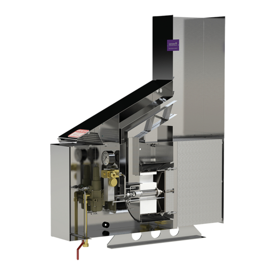
ELECTRODE 62589 rev3 DATA PLATE FUEL SYSTEM Figure 3 P-5050 TEG General Assembly Model P-5050 Thermoelectric Generator The TEG generates electrical power from heat energy. The overall process is: Provide fuel, mix it with air and ignite making heat available. -
Page 20: Figure 4 P-5050 Fuel System General Assembly
Generate electrical power from the temperature difference created across thermo- electric materials housed within the power unit Make the electrical power available to the load The main parts of the model P-5050 TEG, with CP attached, are shown in Figure 3. 4.1.1 Fuel System Components making up... - Page 21 SI and the SI will begin another three start trials. If the optional TEG Controller board is installed: Press the Reset (S3) or send a SCADA Reset signal to the TEG Controller board See Figure 7. Gentherm Global Power Technologies P-5050 62553 Rev.8...
-
Page 22: Figure 5 Burner General Assembly
NUT, 10-32, 316 SS WING NUT, 10-32 SS SCREW, 8-32 X 1/2 SS W/LOCK WASHER PIN, MOUNTING, SI ELECTRODE WING NUT, 5/16-18, SS 62591 rev 1 SCREW, 10-32 X 1-1/4, SS Figure 5 Burner General Assembly Gentherm Global Power Technologies P-5050 62553 rev.8... -
Page 23: Figure 6 Model P-5050 Power Unit Electrical Output Characteristics
Current Power power output. 63990 rev1 Figure 6 Model P-5050 Power Unit Electrical Electrical output characteristics are Output Characteristics shown in Figure 6. Power peaks in a broad load resistance range of 0.5-0.75 Ω. Rated power of 67 W gross is obtained when the power unit load resistance is within this range, at the beginning of the service life of the TEG. -
Page 24: Converter Limiter
A Converter/Limiter (C/L) is available for use with the model P-5050 TEG. It is intended for use with a model P-5050, or P-5100 TEG requiring either 12 or 24 V DC nominal output. It consists of two separate circuits operating together. The first is a DC/DC Converter that converts the input to 12 or 24V. -
Page 25: Temperature Compensation
Use 5 A slow blow for the model P-5050-12 or a 2.5 A slow blow for the model P-5050-24 TEG. Voltage Sensing Relay: Two independent Voltage Sensing Relays (VSRs) provide a set of contacts to indicate an alarm condition when the output voltage drops below a preset minimum. -
Page 26: Blocking Diode
If a 6.7V TEG is hooked up with another power generating source, it must have an external diode installed. Figure 8 CP Interface System General Assembly Gentherm Global Power Technologies P-5050 62553 rev.8... -
Page 27: Optional Cathodic Protection Interface System
Optional Cathodic Protection Interface System An optional cathodic protection interface system is available for use with the model P-5050 TEG. It provides for adjustment and monitoring of power to a Cathodic Protection (CP) load. The anode and cathode cables enter the cabinet at the bottom and connect directly to a heavy duty terminal block. -
Page 28: Figure 9 Teg Controller Assembly
OPERATOR SWITCHES START STOP SCADA INPUTS RESET AUTO FUEL LOCKOUT SCADA OUTPUTS PRESSURE AUTO SWITCH LOCAL OPTIONAL TEMPERATURE SENSOR VOLTAGE INPUT FUSE BATTERY SUPPLY FUSE 63520 rev2 Figure 9 TEG Controller Assembly Gentherm Global Power Technologies 4-10 P-5050 62553 rev.8... - Page 29 Up and Down buttons can be used to make changes to adjustable values. S7 button – Up Operator button for incrementing an adjust- ment S8 button – Down Operator button for decrementing an adjustment Gentherm Global Power Technologies 4-11 P-5050 62553 Rev.8...
- Page 30 Future option display L15 Indicator Auto mode indicator FE Fuse Voltage supply fuse and adjacent fuse blown 2A fuse indicator FB Fuse Battery supply fuse and adjacent fuse blown 2A fuse indicator Gentherm Global Power Technologies 4-12 P-5050 62553 rev.8...
- Page 31 Press S6 (Adjust) until the display goes off to exit the Adjustment mode. It will also automati- cally time-out and exit Adjustment mode. All variable changes are saved upon exit of the Adjust mode. Note: The Display mode is not available until the Adjustment mode is exited. Gentherm Global Power Technologies 4-13 P-5050 62553 Rev.8...
-
Page 32: 4.7 Intake And Exhaust Flame Arrestors
TEGs suitable for installation in these hazardous areas. The addition of a flame arrestors does not make the Models P-5050 N, P-5100 N and P-5100 L TEGs suitable for use in a hazardous area. For hazardous area use, TEGs require reduced surface temperatures (below hazardous gas ignition temperatures), addition of air intake and exhaust flame arrestors, and other modifications. -
Page 33: Installation
INSTALLATION This section provides installation instructions for the Model P-5050 Thermoelectric genera- tor. Precautions WARNING: The installation must conform with local codes or, in the absence of local codes, with the CSA-B149.1 Natural Gas and Propane Installation Code and CSA-B149.2, Propane Storage and Handling. The TEG must be kept clear and free from combustible materials, gasoline and other flammable vapors and liquids. -
Page 34: Unpacking
Unpacking Unpack the TEG from its shipping crate, keep the crate until the TEG is operational. Locate and identify the following items that were shipped with the P-5050 TEG: • Fin Duct • Rain Cap • Thread Sealing Compound •... -
Page 35: Mounting
MOUNTING HOLES 62593 rev1 Figure 11 Model P-5050 Mounting Dimensions Supplying Fuel This topic describes how to connect the fuel supply and gives background information for consideration when providing fuel to the P-5050 TEG. Gentherm Global Power Technologies P-5050 62553 Rev.8... -
Page 36: Figure 12 Applying Thread Sealant
344 kPa (50 psig). If it is expected that the fuel supply pressure will vary greatly, the use of an additional primary regulator is recommended. This will hold the input pressure relatively constant. Gentherm Global Power Technologies P-5050 62553 rev.8... -
Page 37: Figure 13 Setting-Up The P-5050 Teg
VALVE PRESSURE PRESSURE GAUGE SWITCH FUEL LINE REGULATOR REGULATOR ADJUSTING SCREW PRESSURE REGULATOR VENTURI ADJUSTMENT FUEL INLET SCREW VALVE SPARK ELECTRODE VENT LINE POWER UNIT 62954 rev1 Figure 13 Setting-up the P-5050 TEG Gentherm Global Power Technologies P-5050 62553 Rev.8... - Page 38 Clean Fuel: The fuel used to operate the P-5050 TEG must be clean and dry. See Technical Specifications section for full gas specifications. If dirty fuel is anticipated then a customer supplied in-line fuel filter is recommended. Low Temperature: Regulator freeze-off can be minimized by limiting, i.e. regulating, the incoming supply pressure to 138 kPa (20 psig).
-
Page 39: Figure 14 Wiring Diagram P-5050 Teg For 12 Or 24 V
Figure 14 Wiring Diagram P-5050 TEG for 12 or 24 V Gentherm Global Power Technologies P-5050 62553 Rev.8... -
Page 40: Figure 15 Wiring Diagram P-5050 Teg For 12 Or 24V With Optional Teg Controller
Figure 15 Wiring Diagram P-5050 TEG for 12 or 24V with optional TEG Controller Gentherm Global Power Technologies P-5050 62553 rev.8... -
Page 41: Figure 16 Wiring Diagram P-5050 Teg For 6.7V
Figure 16 Wiring Diagram P-5050 TEG for 6.7V Gentherm Global Power Technologies P-5050 62553 Rev.8... -
Page 42: Connecting Customer Load
TEG, see Figure 18. Remove the fuel system and remove the baffle plate to gain access to the holes in the TEG cabinet for mounting the CP InterfacNote: Always mount the CP interface system in an upright position and allow the free flow of air through the unit. Gentherm Global Power Technologies 5-10 P-5050... -
Page 43: Figure 18 Cp Installation
TB-1. 5.8.3 Connection of CP Load Wire the CP load directly to the CP interface system. Feed the CP anode and cathode load cables into the CP box and terminate. Gentherm Global Power Technologies 5-11 P-5050 62553 Rev.8... - Page 44 Gentherm Global Power Technologies 5-12 P-5050 62553 rev.8...
-
Page 45: Startup And Shutdown
STARTUP AND SHUTDOWN This section describes how to startup and shutdown the model P-5050 TEG. Before Starting Before starting the TEG perform these steps: Make sure that all of the connections in the fuel system are tight and have been checked for leaks. - Page 46 Gentherm Global Power Technologies P-5050 62553 rev.8...
-
Page 47: Power Output Evaluation
Required V or Setup Power at Site Power from the P-5050 TEG is produced by the difference in temperature between the burn- er and the cooling fins. This means the power output of the TEG is affected by the ambient temperature surrounding the generator at site. - Page 48 Note: Avoid setting-up the TEG to run at higher V or setup power values, as its life may be affected. This method is suitable for ambient temperatures of up to 65.5ºC (150ºF). If in doubt contact Gentherm Global Power Technologies’ Customer Service Department for guidance. Example: Ambient temperature at site is 35ºC.
- Page 49 . It will climb as shown in Figure 20. Caution: Do not allow measured V to exceed that required V , for present ambi- ent temperature, otherwise overheating may cause irreparable damage to the power unit. Gentherm Global Power Technologies P-5050 62553 Rev.8...
- Page 50 , for present ambi- ent temperature, otherwise overheating may cause irreparable damage to the power unit. When the Vset measurement is completed, reattach the customer load to terminals 7 (+) and 8 (-) of TB-1. Gentherm Global Power Technologies P-5050 62553 rev.8...
-
Page 51: Adjustment
ADJUSTMENT This section describes how to adjust the Model P-5050 Thermoelectric generator. Note: Typical settings are 41 to 48 kPa (6.0 to 7.0 psi) for natural gas and 48 to 55 kPa (7.0 to 8.0 psi) for propane. Note: Good record keeping is necessary for long term follow-up. Use the TEG Performance Log, located at the end of this manual, for recording details each time adjustments are made or servicing is carried out. -
Page 52: Power Output Adjustment
If the site elevation is 1000 m (3281 ft.) then 2.5 kPa (0.36 psig) must be added to the pressure on the data plate. Figure 22 Change in V Versus Air-Shutter Adjustment, Typical Gentherm Global Power Technologies P-5050 62553 rev.8... - Page 53 Notice that the peak of the graph is within one quarter of a turn, either direction, of the adjusting screw. Set the adjusting screw so that it is one-half turn clockwise, air-rich, verify CO levels are below 800 ppm (see section 8.1.2.1) and proceed to e). Tighten the lock-nut. Gentherm Global Power Technologies P-5050 62553 Rev.8...
- Page 54 TEG, the CO measurement must be in the free air state. In a free air measurement, the allowable CO rate is 800 ppm however a correctly adjusted P-5050 will produce less than 120 ppm CO air free. In order to be able to determine the levels of air-free CO...
-
Page 55: Adjustment Of C/L
Tighten the lock nut and replace the cover on the fuel regulator. Adjustment of C/L A C/L is available for use with the model P-5050 TEG. This text describes how to adjust the C/L, if applicable. Gentherm Global Power Technologies P-5050 62553 Rev.8... - Page 56 It is factory set at 23.0V and 28.5V (Model P-5050-24) or 11.5V and 14.3V (Model P-5050-12). The VSR is rated for 2A at 30V DC and will take up to 14 AWG stripped wire. The Remote VSR Terminal Option will allow for a wire size of 10AWG with a ring or fork terminal termination.
-
Page 57: Enabling Temperature Compensation
Switch 2- ON Adjustment of Optional CP Interface System An optional CP interface system is available for use with the model P-5050 TEG. This text describes how to adjust the CP interface system, if applicable. 8.4.1 CP Power Output Adjustment The 0-1Ω... -
Page 58: Figure 24 Cp Interface System, Series Wiring Diagram
Note: TEG fuel pressure may be adjusted to fine tune the CP output. Fuel pressure within 10% of that marked on the data plate is recommended to prevent flame out. Figure 24 CP Interface System, Figure 25 CP Interface System, Series Wiring Diagram Parallel Wiring Diagram Gentherm Global Power Technologies P-5050 62553 rev.8... -
Page 59: Adjustment Of The Optional Remote Start System (Teg Controller)
Press the Adjust button until the display goes off to exit the Adjustment mode. It will also automatically timeout and exit Adjustment mode. All variable changes are saved upon exit of the Adjust mode. Note: The Display mode is not available until the Adjustment mode is exited. Gentherm Global Power Technologies P-5050 62553 Rev.8... - Page 60 Gentherm Global Power Technologies 8-10 P-5050 62553 rev.8...
-
Page 61: Maintenance
MAINTENANCE This section describes how to maintain the model P-5050 TEG. Before attempting to main- tain the TEG the qualified service person should be thoroughly familiar with its: • technical specifications; • process description; • installation; • startup and shutdown;... - Page 62 Routine Service, Section 9.1.3. Note: A dirty fuel filter may cause a drop in fuel pressure. A plugged fuel ori- fice will change fuel flow without a change in fuel pressure. Gentherm Global Power Technologies P-5050 62553 rev.8...
- Page 63 Start the TEG. See Startup and Shutdown Section 6. Check V , record and adjust if necessary. See Power Output Evaluation Section 7 and Adjustment Section 8, as applicable. Record the final setup in the TEG Performance Log before leaving site. Gentherm Global Power Technologies P-5050 62553 Rev.8...
-
Page 64: Fuel System Maintenance
Remove the four screws from the bot- tom of the regulator. Remove the filter, and gasket. See Figure 26. Figure 26 Pressure Regulator Gentherm Global Power Technologies P-5050 62553 rev.8... - Page 65 Connect the fuel line to SV valve and orifice, then tighten the fuel line fittings. Leak check all connections using a commercial leak detector. WARNING: Check for fuel leaks after any fuel system service. Gentherm Global Power Technologies P-5050 62553 Rev.8...
-
Page 66: Burner Maintenance
The procedures below give the steps for inspecting the burner components. Gentherm Global Power Technologies P-5050 62553 rev.8... -
Page 67: Figure 27 Burner Assembly Cross Section
Remove the 2 bolts mounting the fuel regulator to the cabinet wall and remove the fuel system. Remove the 2 screws from each side of the cabinet baffle and remove baffle from cabinet. Note: Try not to disturb the air shutter setting. Gentherm Global Power Technologies P-5050 62553 Rev.8... - Page 68 Note: The orifice fitting only needs to be finger tight when threaded to the front of the air box lid. Before re-starting the TEG, leak check all fuel connections. WARNING: Check for fuel leaks after any fuel system service. Gentherm Global Power Technologies P-5050 62553 rev.8...
-
Page 69: System Maintenance
3 to 6 mm (1/8 to 1/4 in.). The ceramic rod should extend about 25 mm (1 in.) from the holding screw. Tighten the wing-nut only until it is snug. Figure 28 Electrode Protrusion From Air Box Lid Gentherm Global Power Technologies P-5050 62553 Rev.8... - Page 70 Follow these steps to check the battery voltage: Open the front of the TEG, then open the cover door to the electronics, located inside the door assembly. Locate the battery, see Figure 7. Gentherm Global Power Technologies 9-10 P-5050 62553 rev.8...
-
Page 71: C/L Examination
C/L should be checked and serviced as necessary. Use the procedures below to help determine if the C/L could be dam- aged. Gentherm Global Power Technologies 9-11 P-5050 62553 Rev.8... -
Page 72: Power Unit Examination
Run a jumper wire from terminal 2 to the TEG chassis and watch the voltage read- ing. Remove the jumper wire. Any fluctuation in voltage may indicate an internal short within the power unit. Gentherm Global Power Technologies 9-12 P-5050... - Page 73 = internal resistance (ohms) = momentary open circuit voltage (V) = load voltage (V) = load current (A) = precision load resistance (ohms) = voltage measured across terminals 5 and 6 (V) Gentherm Global Power Technologies 9-13 P-5050 62553 Rev.8...
-
Page 74: Figure 29 Momentary Open Circuit Diagram
= 4.92 / 10.59 = 0.46 ohms Internal resistance is acceptable, < 0.58 ohms. For further information or assistance, please contact the Customer Service Department at Gentherm Global Power Technologies. Figure 29 Momentary Open Circuit Diagram Gentherm Global Power Technologies 9-14 P-5050 62553 rev.8... - Page 75 Ignition control system Maintain the SI system Maintenance faulty Air filter dirty Clean the air filter Maintenance Air shutter adjustment Adjust the air-shutter Adjustment incorrect continued on next page Gentherm Global Power Technologies 10-1 P-5050 62553 Rev.8...
-
Page 76: Troubleshooting
Adjust the TEG fuel Adjustment is too high adjustment incorrect manifold pressure Output voltage is too C/L* damaged Adjust the C/L Adjustment high C/L* adjustment Adjust the C/L Adjustment incorrect *applicable for L/C option only Gentherm Global Power Technologies 10-2 P-5050 62553 rev.8... -
Page 77: Part List
PART LIST This section lists the parts that form the equipment. For parts and service please contact Gentherm Global Power Technologies’s Customer Service Department at: Gentherm Global Power Technologies Customer Service Department Direct: 001-403-720-1190 GLOBAL POWER TECHNOLOGIES Fax: 001-403-236-5575 Switchboard: 001-403-236-5556 Unit #16, 7875 - 57th SE E-mail: customer.service@gentherm.com... -
Page 78: Model P-5050 Teg
NUT, HEX, 1/4-20, SS 2814-00541 WASHER, LOCK, SPRING, 1/4, SS 2814-00557 WASHER, FLAT, 1/4” SS 4900-62120 FUEL LINE, P-5050/P-5100 4900-65821 FUEL LINE, SS FUEL SYSTEM, P-5050/P-5100 4900-62064 BAFFLE, INNER CABINET, P-5050/P-5100 4200-00688 ORIFICE, 6, 0.0185, 5060-N 4200-00686 ORIFICE 4, 0.0145, 5060-L 2508-07410... - Page 79 4900-62126 EXHAUST TUBE ASSY, P-5050/P-5100 4900-62065 LINER, EXHAUST, P-5050/P-5100 4900-62067 RAIN CAP ASSEMBLY, P-5050/5100 4900-62113 COVER ASSY, UPPER, FIN DUCT, P-5050/P-5100 4100-61552 FIN DUCT, UPPER, P-5050 4100-61551 FIN DUCT, LOWER, P-5050 2514-20535 SCREW, HEX HD, 1/4-20 X 5/8, SS 7000-61555...
- Page 80 LIMITER/CONVERTER ASSY, 24V, P-5050/P-5100 (OPTIONAL) 6300-63515 LIMITER/CONVERTER ASSY, 12V, RS, P-5050/P-5100 (OPTIONAL) 6300-63516 LIMITER/CONVERTER ASSY, 24V, RS, P-5050/P-5100 (OPTIONAL) 6300-65206 CP INTERFACE ASSEMBLY, P-5050-6.7V (NOT SHOWN) (OPTIONAL) 6300-65207 CP INTERFACE ASSEMBLY, P-5050-12V (NOT SHOWN) (OPTIONAL) 6300-65245 CP INTERFACE ASSEMBLY, P-5050-24V (NOT SHOWN) (OPTIONAL) 2400-56980...
-
Page 81: Model P-5050 Burner
INSULATION BLOCK, P-5050/P-5100 4000-61871 SPACER, VENTURI, P-5050/P-5100 4900-62004 VENTURI, P-5050 4000-61870 BURNER COVER, P-5050/P-5100 4500-62118 AIR BOX ASSY, W INTAKE ARRESTORS, P-5050/P-5100 4900-63988 AIR BOX ASSY, NON FA,P-5050/P-5100 4900-07004 PIN, MOUNTING, SI ELECTRODE 2756-07005 NUT, WING, 5/16-18, SS 2710-00601 NUT, WING, 10-32, SS... -
Page 82: Model P-5050 Fuel System
NIPPLE, 1/4 NPT X 6” LG. BRASS 3034-21569 ELBOW, Street 1/4 NPT, B-4-SE 3100-63312 REGULATOR, FISHER 67CFR, 0-20 PSI, UL 144 & UL 252, P-5050/P-5100 3052-58949 PLUG, 1/4” NPT X 7/8” STEEL, UMBRAKO 1105766 3044-00501 NIPPLE, HEX, 1/4 NPT X 1 1/8, BRASS... -
Page 83: Figure 33 Model P-5050 Ss Fuel System
11.4 Model P-5050 Optional Stainless Steel Fuel System 62563 rev0 Figure 33 Model P-5050 SS Fuel System Item Part No. Description 3091-21689 VALVE, BALL, 1/4” 2000 LB, 316 SS, V-TEK V2 3041-62559 NIPPLE, 1/4 NPT X 6” L, SS 3031-02356... -
Page 84: Model P-5050 Electrical
SCREW, FAST LEAD , KNURLED, SS, SOUTHCO 09-13-102-26 4900-63039 DEAD FRONT, ELECTRICAL ASSY, P-5050/P-5100 2400-63126 PCB ASSY, LC DC/DC CONVERTER, MEDIUM POWER, P-5050/P-5100 2400-64879 PCB ASSY, LC DC/DC LIMITER, MEDIUM POWER, P-5050/P-5100 2508-58437 SCREW, CAP, HEX SOCKET, 8-32 x 3/8”, 18.8 SS 2400-24559 BATTERY, 6V, 5.0Ahr, Monobloc, AEI 108539... -
Page 85: Cathodic Protection
The duel Scale meter displays voltage at the terminal block, and current when the PUSH TO READ AMPS button is depressed. The meter is accurate to +/- 3% of full scale. Figure 35 Cathodic Protection Interface Cabinet Gentherm Global Power Technologies 12-1 P-5050 62553 Rev.8... -
Page 86: Figure 36 Cp Interface System, Series Wiring Diagram
300 Watt resistor from the left position to the center position of the heavy duty terminal block Figure 36 CP Interface System, Figure 37 CP Interface System, Series Wiring Diagram Parallel Wiring Diagram Gentherm Global Power Technologies 12-2 P-5050 62553 rev.8... - Page 87 Complete parts listings are given in the next pages for the various Cathodic Protection Interface Systems available. The required system for various TEGs are listed below. GPT TEG Item System Description P-5050-6.7 6300-65206 CP Interface Assembly, P-5050-6.7V P-5050-12 6300-65207 CP Interface Assembly, P-5050-12V P-5050-24 6300-65245 CP Interface Assembly, P-5050-24V P-5100-6.7...
-
Page 88: Figure 38 Cathodic Protection System Parts Identification
Figure 38 Cathodic Protection System Parts Identification Gentherm Global Power Technologies 12-4 P-5050 62553 rev.8... - Page 89 Wire, #10, wht/red, TIN-PLT-COP 4.25 2120-00133 Wire, #10, red, TIN-PLT-COP 4900-02134 Meter Panel, CP, Brushed 2420-06226 Meter, GE/TCA, 251-324-ECXS 2510-00255 Screw, Mach, P-H-P, 10-32 x 3/8, SS 2510-00256 Screw, Mach, P-H-P, 10-32 x 1/2, SS Gentherm Global Power Technologies 12-5 P-5050 62553 Rev.8...
- Page 90 Washer, Lock, Spring, #10, CAD 2508-00254 Screw, Mack, P-H-P, 8-32 x 3/8, SS 2808-00468 Washer, Lock, Int, #8, SS 3600-04795 Label, Cathodic Protection Interface Part of Item 29 Button, Red, 61F-675, For ALCO Switch Gentherm Global Power Technologies 12-6 P-5050 62553 rev.8...
-
Page 91: Heat Recovery System Option
Heat Recovery System (HRS) Option 13.1 Introduction The Heat Recovery System (HRS) Option is available for P-5050 and P-5100. This option allows for waste heat recover, to warm building interiors where required, see Figure 39. The TEG configured for the HRS application includes an HRS specific rain cap, exhaust tube as- sembly, and burner configuration. -
Page 92: 13.3 Teg Operation
13.3 TEG Operation Refer to Sections 2 - 10 of this manual for TEG operations Gentherm Global Power Technologies 13-2 P-5050 62553 rev.8... -
Page 93: Figure 40 Model P5050 Hrs Configuration
G17 G7 G17 G7 UNIT P-5050 for HRS G15 G10 G9 G23 G24 G25 66660 rev0 G12 G10 G9 Figure 40 Model P-5050 HRS Configuration Item Part No. Description See Fig 30 6100-66654 BURNER ASSEMBLY, W/INTAKE ARRESTOR, HRS, P-5050 6100-61564... -
Page 94: Figure 41 Model P5050 Hrs, Burner
See Fig 31. 4000-66631 BURNER COVER, TOP ELECTRODE, P-5050/P-5100 4500-66635 AIR BOX ASSY, TOP ELECTRODE, P-5050/P-5100 J12-J17 See Fig 31. 4900-66632 LID W/ ARRESTORS, ASSEMBLY, TOP ELECTRODE P-5050/P-5100 J19-J23 See Fig 31. Gentherm Global Power Technologies 13-4 P-5050 62553 rev.8... -
Page 95: Teg Performance Log
TEG PERFORMANCE LOG MODEL NO: TEG SERIAL NO: FUEL TYPE: LIMITER/CONVERTER SERIAL NO: CP INTERFACE SERIAL NO: MAINTENANCE REMARK Gentherm Global Power Technologies 14-1 P-5050 62553 Rev.8... - Page 96 TEG PERFORMANCE LOG MODEL NO: TEG SERIAL NO: FUEL TYPE: LIMITER/CONVERTER SERIAL NO: CP INTERFACE SERIAL NO: MAINTENANCE REMARK Gentherm Global Power Technologies 14-2 P-5050 62553 rev.8...
- Page 97 TEG PERFORMANCE LOG MODEL NO: TEG SERIAL NO: FUEL TYPE: LIMITER/CONVERTER SERIAL NO: CP INTERFACE SERIAL NO: MAINTENANCE REMARK Gentherm Global Power Technologies 14-3 P-5050 62553 Rev.8...
- Page 98 Gentherm Global Power Technologies 14-4 P-5050 62553 rev.8...
Need help?
Do you have a question about the P-5050 and is the answer not in the manual?
Questions and answers
il fornitore ha creato la classificazione delle aree di pericolo del prodotto per l'utilizzo di gas naturale?
Yes, Gentherm considers the P-5050N model, which operates on natural gas and includes a flame arrestor, to be compliant with API Recommended Practice 12N and suitable for use in unclassified areas. However, it is not suitable for hazardous areas such as Class 1, Division 2.
This answer is automatically generated