
Summary of Contents for Antano Group LG2004
- Page 1 Uso e manutenzione Use and maintenance handbook MONTASCALE A CINGOLI TRACKS MOBILE STAIRWAY CLIMBER LG2004 LG2004/150 LG2004/180 LG2004/150/A008 Rel.7_160715...
-
Page 3: Table Of Contents
Smontaggio del manubrio .......................... 11 Impostazione aggancio carrozzina ......................12 Sgancio carrozzina ........................... 14 Regolazione poggiatesta .......................... 14 Installazione delle pedane e regolazioni per LG2004/150/A008 .............. 15 CARATTERISTICHE TECNICHE ........................19 Dimensioni ..............................19 Tabella dati tecnici ............................. 19 Caratteristiche scale ..........................19 USO PREVISTO DAL COSTRUTTORE ...................... -
Page 4: Dati Di Marcatura
DATI DI MARCATURA Numero di serie - Serial number Modello - Item ..Anno di costruzione - Production year ..ANTANO GROUP s.r.l Via Todi, 15 zi. Torre Matigge Portata massima - Maximum load ..06039 Trevi (Pg) Massa complessiva - Total weight ..Tel. 0742 381269... - Page 5 • Il conduttore deve tenere saldamente ambedue le mani sul • Il conduttore si deve posizionare sempre a monte rispetto al manubrio. mezzo; il montascale quindi non deve essere impiegato in modo diverso, ad esempio con il conduttore a valle ove si • Il dispositivo deve essere utilizzato osservando le seguenti creerebbe un alto pericolo per il conduttore, per il trasportato prescrizioni: e per la macchina stessa. - Durante la movimentazione il passeggero deve mantenere obbligatoriamente una posizione eretta, con le spalle e la La carrozzina testa accostata alla spalliera. • Le regolazioni e le impostazioni del montascale sono deter- - Non utilizzare l’ausilio come mezzo per trasportare cose minate dalla costruzione della carrozzina.
- Page 6 • Nell’affrontare la marcia su scale occorre controllare l’ap- posito l’indicatore di pendenza: bolla è nella zona verde si può procedere; l’inclinazione della scala è inferiore a 35°. bolla fra il verde e il rosso posizione critica, inclinazione limite; potete affrontare la scala ma con molta attenzione. bolla nella zona rossa vietato procedere.
-
Page 7: Pittogrammi
2.2 Pittogrammi I seguenti pittogrammi possono essere presenti sia sul dispositivo che all’interno del presente manuale. Attenzione! pericolo Leggere il manuale d’istruzione Operazioni che devono essere compiute da personale Rischio schiacciamento dita nella trasmissione mecca- qualificato nica Attenzione! Informazione importante Rischio elettrico Pericolo: Accumulatore Attenzione! Informazione importante... -
Page 8: Disimballo
Obbligatorio APIRAEE (www.apiraee.it) al quale lo stesso ha aderito, comunicando il seguente codice produttore di iscrizione al registro nazionale dei Produttori di Apparecchiature Elettriche ed Elettroniche: IT13080000008116 DESCRIZIONE DEL SISTEMA Il Montascale LG2004 consente di trasportare una carrozzina con un passeggero disabile sulle scale di un edificio grazie a un particolare sistema elettromeccanico in grado di superare gli scalini. -
Page 9: Componenti Del Dispositivo
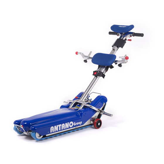
4.1 Componenti del dispositivo PUNTO DI EQUILIBRIO Manubrio 15 Manopola regolazione poggiatesta Base motorizzata 16 Pomello regolazione poggiaaschiena e agganci Poggiatesta 17 Connettore del carica-batteria Impugnature manubrio 18 Ruote di manovra Pulsante DISCESA (AVANTI) 19 Cingoli in gomma Pulsante SALITA (INDIETRO) 20 Quadro con chiave Aggancio carrozzina destro 21 Maniglia posteriore... - Page 10 Il pulsante di emergenza 11 deve essere utilizza- to solo in particolari condizioni di avaria, ovvero quando il sistema di trazione dovesse rimanere in moto anche rilasciando i pulsanti di SALITA e DISCESA. 30 Sicurezza aggancio manubrio 31 Innesto a forcella 32 Albero di aggancio...
- Page 11 Chiave abilitazione funzione montascale Se la chiave è disinserita o in posizione 0 (OFF) nessuna funzione elettrica è abilitata. Indicatore di carica della batteria (vedi capitolo “carica batterie”) Pulsante marcia avanti e indietro ausilio 33 Contatti elettrici lato manubrio 34 Contatti elettrici lato base motorizzata 35 Cinture di sicurezza...
-
Page 12: Montaggio Dell'ausilio
Queste operazioni devono essere compiute esclusivamente da personale qualificato o centro di assistenza MONTAGGIO DELL’AUSILIO Il dispositivo viene fornito smontato in due parti: corpo mac- china motorizzato e manubrio. 5.1 Montaggio del manubrio • Prelevate il manubrio ompleto di cinture di sicurezza e, con una certa attenzione, portatelo sulla base motorizzata, in corrispondenza dell’albero di innesto A. Attenzione Non tentate di innestare il manubrio sull’albero posteriore in quanto potreste danneggiare i contatti elettrici... -
Page 13: Smontaggio Del Manubrio
Queste operazioni devono essere compiute esclusivamente da personale qualificato o centro di assistenza • Sollevate ora la leva di sicurezza S fino a fine corsa. Se la leva di sicurezza S non è posizionata correttamente il funzionamento del montascale è disabilitato Le leve di sicurezza S (superiore) e S1 (inferiore) sono col- legate fra di loro tramite una corda flessibile;... -
Page 14: Impostazione Aggancio Carrozzina
Queste operazioni devono essere compiute esclusivamente da personale qualificato o centro di assistenza Le leve di sblocco L (superiore) e L1 (inferiore) sono colle- gate fra di loro tramite una corda flessibile; il movimento di una leva produce anche un movimento relativo sull’altra. • La leva inferiore L1 deve essere utilizzata solo quando la leva superiore L è inefficace a causa di qualche problema;... - Page 15 Queste operazioni devono essere compiute esclusivamente da personale qualificato o centro di assistenza • Tirate il pomello P e aprite i bloccaggi della carrozzina. • Allentate le manopole K e spostate i bloccaggi della carrozzima verso l’esterno. • Tirate verso l’esterno i pomelli B con ritorno a molla e ruotateli per farli rimanere bloccati in posizione aperta.
-
Page 16: Sgancio Carrozzina
Queste operazioni devono essere compiute esclusivamente da personale qualificato o centro di assistenza • Sbloccate i pomelli sia sul lato destro che sinistro in modo da bloccare efficacemente la carrozzina. Fra la posizione di apertura e chiusura è stata studiata una posizione di sicurezza che l’utente può trovare a circa due millimetri dalla posizione di chiusura. Questa posizione blocca completamente il movimento del perno di bloccaggio. -
Page 17: Installazione Delle Pedane E Regolazioni Per Lg2004/150/A008
Queste operazioni devono essere compiute esclusivamente da personale qualificato o centro di assistenza 5.6 Installazione delle pedane e regolazioni per LG2004/150/A008... - Page 18 Queste operazioni devono essere compiute esclusivamente da personale qualificato o centro di assistenza...
- Page 19 Queste operazioni devono essere compiute esclusivamente da personale qualificato o centro di assistenza Clic !
- Page 20 Queste operazioni devono essere compiute esclusivamente da personale qualificato o centro di assistenza Clic !
-
Page 21: Caratteristiche Tecniche
CARATTERISTICHE TECNICHE Per i dati non riportati in questa sezione vedi targa matricola apposta sull’apparecchio 6.1 Dimensioni LG 2004/150 A008 1440 6.2 Tabella dati tecnici LG 2004 LG 2004/150 LG 2004/180 LG 2004/150 A008 Peso complessivo ausilio 58 kg 59 kg 60 kg 84 kg - peso corpo macchina... -
Page 22: Uso Previsto Dal Costruttore
USO PREVISTO DAL COSTRUTTORE Leggere il manuale d’istruzione USO PREVISTO L’uso giornaliero del dispositivo è autorizzato solo a condizione che tutti gli elementi di sicurezza e le parti funzionali siano efficienti. Il dispositivo è stato studiato per consentire il trasporto di una carrozzina con una persona a bordo sulle scale di un edificio L’ausilio è previsto per l’utilizzo in ambienti residenziali o similari, comunque al coperto. L’ausilio deve essere utilizzato esclusivamente per il trasporto della carrozzina verificata dal responsabile che ha rilasciato l’abilitazione a condurre il mezzo sulle scale. L’ausilio può procedere solo su superfici piane e con fondo stabile. L’uso è esclusivamente quello descritto nel presente manuale; raccomandiamo quindi di leggere attentamente le presenti istruzioni per acquisire la massima familiarità con la funzionalità del dispositivo. CONDUZIONE SU SCALE Per condurre il mezzo su scale, il conduttore deve essere in possesso di una abilitazione rilasciata dall’azienda produttrice o da un suo mandatario autorizzato, solo dopo che questa persona ha acquisito una diretta istruzione teorico- pratica (training) e solo dopo aver dimostrato praticamente di essere in grado di eseguire tutte le operazioni descritte nel presente manuale in sicurezza, in particolare per le fasi di conduzione del mezzo, con passeggero a bordo, su scale, sia in salita che in discesa. -
Page 23: Uso Dell'ausilio
USO DELL’AUSILIO Prima dell’uso quotidiano del dispositivo verificare sempre lo stato e l’efficienza generale dell’ausilio e la carica delle batterie 8.1 Carica della batteria La carica deve avvenire in ambiente areato. La carica della batteria deve essere compiuta uti- Collegamento Inserite il connettore. -
Page 24: Verifica Pendenza Delle Scale
Queste operazioni devono essere compiute esclusivamente da personale qualificato o centro di assistenza 8.2 Verifica pendenza delle scale Rilevare la pendenza delle scale 35° Attenzione! prima di affrontare una scala per la prima volta oc- corre accertarsi che la sua inclinazione sia nei parametri stabiliti incliazione massima 35°(corrisponde ad una pendenza del 70%) 70 cm... -
Page 25: Uso Quotidiano
8.3 Uso quotidiano Prima dell’uso quotidiano del dispositivo verificare sem- pre lo stato e l’efficienza generale dell’ausilio e la carica delle batterie Ogni giorno, quando l’operatore si accinge ad utilizzare l’ausilio, deve verificare sempre i seguenti punti: • Stato di carica della batteria. • Se la batteria è in riserva, provvedete subito alla sua ricarica • Funzionalità degli elementi di sicurezza: pulsante di emer- genza, indicatore di pendenza • Assetto e stabilità del manubrio, suo corretto ancoraggio. • Assetto e stabilità della carrozzina; nessun elemento di fissaggio deve essere lento o in posizione non sicura da garantire il corretto ancoraggio della carrozzina • Stato e funzionalità delle cinture di sicurezza. -
Page 26: Conduzione Su Scale
• Azionate i freni delle ruote della carrozzina. • Agganciate la carrozzina come descritto nel capitolo 5. • Controllate che le cinture di sicurezza siano ben allacciate e strette a sufficienza per garantire la stabilità del passeggero. • Ruotate il manubrio verso di voi fino ad agganciarlo stabil- mente. • Verificate sempre il corretto aggancio del manubrio prima di procedere. • Posizionate la leva di sicurezza S in alto, altrimenti il mon- tascale non risponderà ai comandi. 8.6 Conduzione su scale La persona che conduce il mezzo su scale, sia in salita che in discesa, deve essere in possesso di una abilitazione che vie- ne concessa dall’azienda produttrice o da un suo mandatario Leggere il manuale d’istruzione autorizzato, solo dopo che questa persona ha acquisito una diretta istruzione teorico- pratica e solo dopo aver dimostrato praticamente di essere in grado di eseguire tutte le operazioni... - Page 27 Non deve mai essere affrontata una scala se il passeggero Verificare che le dimensioni degli scalini siano compati- non è in posizione eretta (posizione di movimento, vedi capi- bili con le specifiche descritte (vedi capitolo 6). In caso contrario NON AFFRONTARE le scale, eventual- tolo USO). mente chiedere informazioni direttamente al costruttore Utilizzare le specifiche cinture di sicurezza per assicurare il o al suo mandatario.
-
Page 28: Salire Le Scale
8.7 Salire le scale CICLO DI SALITA (S1..S5) Avvicinamento L’avvicinamento del montascale alla scala poò essere compiu- to, a scelta del conduttore, in due modi: a) premendo il pulsante “INDIETRO” : Il motore fa arretrare il montascale mentre il pulsante rimane premuto b) Condotto a mano dopo aver premuto il pulsante di solleva- mento. In prossimità delle scale occorre premere il pulsante “IN- DIETRO”... - Page 29 • Continuate a premere il pulsante di salita e tirate verso di voi fino a portare l’intera sagoma dell’ausilio sul piano. Il montascale viene tirato verso il con- duttore Le scale sono terminate Il montascale viene azionato indietro verso il conduttore • Ponete la chiave del quadro in posizione O (OFF) e sfilatela per assicurarsi che nessuno se non il conduttore abilitato possa utilizzare il dispositivo. • Potete ora liberare la carrozzina.
-
Page 30: Scendere Le Scale
8.8 Scendere le scale CICLO DI DISCESA (D1..D6) Avvicinamento • Verificate che il pulsante di emergenza sia sbloccato seguendo le indicazioni di RESET stampate sul pulsante stesso. • Verificate che il passeggero abbia le cinture di sicurezza allacciate. • Controllate che il passeggero abbia una postura corretta. • Non trasportate oggetti di alcun genere. • Verificate che le cinture di sicurezza siano ben allacciate e STOP che non vi siano oggetti, abiti, sciarpe e comunque parti di vestiario pendenti che possano interferire con il movimento del montascale stesso Il montascale è... - Page 31 Discesa • Premete il pulsante di discesa “AVANTI” : il montascale scenderà davanti a voi in modo lineare e costante. In qualsiasi momento rilasciando il pulsante il montascale si ferma. • Continuate a scendere fin quando raggiungerete il piano. Il montascale è in fase di discesa Il montascale è in contatto con il piano Le scale sono terminate • Ponete la chiave del quadro in posizione O (OFF) e sfilatela per assicurarsi che nessuno se non il conduttore abilitato...
-
Page 32: Trasporto Del Montascale
8.9 Trasporto del montascale Operazioni che devono essere compiute da due persone addestrate all’uso Il montascale può essere trasportato con un mezzo dotato di sufficiente piano di carico: automobile, furgone, carrello, Rischio schiacciamento dita nella trasmissione mec- seguendo le seguenti istruzioni. canica Il mezzo dovrà... -
Page 33: Manutenzione Ordinaria
MANUTENZIONE ORDINARIA Queste operazioni possono essere eseguite dall’utilizzatore. Qualsiasi operazione di manutenzione deve essere eseguita con il caricabatterie scollegato dal montascale e con la chiave sfilata dal quadro. L’ausilio necessita di una ordinaria manutenzione come qualsiasi altro prodotto, in modo da mantenerlo in perfetto stato di efficienza, anche dopo anni di uso. Giornalmente rimuovete residui di cibo, capelli e qualsiasi elemento che può accumularsi, come la polvere; potete per questo impiegare un aspirapolvere domestico. La successiva tabella indica la periodicità con cui le operazioni di manutenzione devono essere eseguite. Un controllo costante e l’attenzione dovranno stimolare l’utilizzatore a eseguire le operazioni necessarie in funzione delle reali necessità. Tabella della manutenzione ordinaria Periodicità... -
Page 34: Pulizia Delle Parti Metalliche
9.1 Pulizia delle parti metalliche Le parti metalliche verniciate possono essere pulite con spray commerciali per uso domestico ma attenzione che non conten- gano alcool o solventi, questi possono scolorire o danneggiare la vernice stessa. Le parti cromate possono essere pulite con normali prodotti per uso domestico e poi asciugate bene. Non utilizzare getti o spruzzi di acqua 9.2 Pulizia delle parti in plastica Per la pulizia delle parti in plastica utilizzate un comune detergente per plastica di uso commerciale, attenendovi alle istruzioni e controindicazioni riportate nelle istruzioni che accompagnano il prodotto. Evitare prodotti a base di solventi o alcool. Non utilizzare getti o spruzzi di acqua 9.3 Pulizia delle ruote Ruotate completamente l’ausilio su un lato in modo che il ma- nubrio poggi sul pavimento;... -
Page 35: Inconvenienti E Rimedi
10 INCONVENIENTI E RIMEDI Le operazioni indicate con questo simbolo devono essere eseguite esclusivamente da personale qualificato o da un centro di assistenza autorizzato come descritto nel capitolo 12 SOGGETTO INCONVENIENTE RIMEDIO Ruote Cigolio durante lo spostamento • pulire le ruote • sostituire ( Comandi Nessun comando elettrico è accettato, • Verificare la carica della batteria, eventualmente... -
Page 36: Manutenzione Programmata
Dopo il periodo di garanzia l’azienda produttrice ha studiato un programma di manutenzione programmata allo scopo di assi- curare sempre le prestazioni dell’ausilio. La manutenzione programmata deve essere eseguita esclusivamente, presso i centri di Assistenza autorizzati. o presso l’a- zienda di produzione Per conoscere i centri di Assistenza più vicini a voi rivolgetevi direttamente al produttore: SERVICE Interventi previsti nella manutenzione programmata ANTANO GROUP s.r.l. Via Todi 15 Zona Ind.le Matigge di Trevi - • controllo dei cingoli 06039 - Trevi (PG) Italy Tel. 0742/381269 Fax. 0742/386574 •... -
Page 37: Aggiuntivi Disponibili Su Richiesta
12 AGGIUNTIVI DISPONIBILI SU RICHIESTA Per l’installazione e l’uso degli aggiuntivi riferitevi alle istruzioni accluse alla fornitura dell’aggiun- tivo stesso ART. A006 Pattini per carrozzine con ruote posteriori ø300 mm ART. A007 Pattini per passeggini ART. A009 ART. A023 Sistema di sicurezza antiribaltamento Attacchi universali ART. -
Page 38: Interventi Di Manutenzione Programmata
Interventi di manutenzione programmata MANUTENZIONE PROGRAMMATA MANUTENZIONE PROGRAMMATA 24 mesi 36 mesi Timbro e firma del centro di assistenza Timbro e firma del centro di assistenza Data Data MANUTENZIONE PROGRAMMATA MANUTENZIONE PROGRAMMATA 48 mesi 60 mesi Timbro e firma del centro di assistenza Timbro e firma del centro di assistenza Data Data... -
Page 39: Interventi Di Manutenzione Straordinaria
Interventi di manutenzione straordinaria Descrizione intervento Descrizione intervento ........................................................................................................................................................................................................................................................................................................................ Timbro e firma del centro di assistenza Timbro e firma del centro di assistenza Data Data Descrizione intervento Descrizione intervento .................... -
Page 40: Garanzia
13 GARANZIA Il prodotto è coperto da una garanzia legale di 24 mesi a partire dalla data di consegna (d. lgs 24/2002) all’acquirente Antano Group e Dir. CE 1999/44) contro qualsiasi difetto di fabbricazione. Nel periodo di garanzia viene assicurata la manutenzione del dispositivo direttamente presso la sede della Ditta produttrice, completamente a carico di quest’ultima, o presso i centri di assistenza dislocati sul territorio. La garanzia non copre le parti soggette ad usura per la loro natura e destinazione (es: batterie, ruote etc) La garanzia non copre: • danni derivati da un utilizzo non conforme o diverso da quanto specificato nel presente manuale • danni derivati da errato montaggio effettuato dal cliente... - Page 41 5.2 Handlebar disassembly ..........................49 Wheelchair hook setting ........................... 50 Wheelchair release ........................... 52 Adjusting the headrest ..........................52 Mounting and adjustment of the ramps on LG2004/150/A008 ..............53 TECHNICAL CHARACTERISTICS ........................57 Dimensions ..............................57 Technical data table ........................... 57 Characteristics of staircase ........................
-
Page 42: Ce Marking Data
CE MARKING DATA Numero di serie - Serial number Modello - Item ..Anno di costruzione - Production year ..ANTANO GROUP s.r.l Via Todi, 15 zi. Torre Matigge Portata massima - Maximum load ..06039 Trevi (Pg) Massa complessiva - Total weight ..Tel. 0742 381269... - Page 43 • The operator must always keep both hands firmly on the • The operator must always be on board machine; so the stair handlebar. chairs must not be used in a different way, for example when the operator is down, otherwise the operator, the person • The device must be used observing the following rules: being transported and the machine may be in danger. - the operator must be over the age of 18. - during movement, the passenger must sit in a completely Wheelchair upright position, with shoulders and head up against the • The adjustments and settings of the stair chairs depend on chair back.
- Page 44 • When putting into gear while climbing check the proper slope indicator: if the bubble lies within the green area you can proceed; the slope of stairs is below 35°. if the bubble lies between the green and red areas the position is critical, the slope is at its maximum allowed limit; you can start climbing very carefully. if the bubble lies within the red area it is forbidden to proceed.
-
Page 45: Pictograms
2.2 Pictograms The following pictograms may be present on the wheelchair or in this manual. Warning, danger Read the instructions manual Operations which must be carried out by qualified per- Risk of crushing fingers in the mechanical transmission sonnel or the service centre Attention! Important information Electrical hazard Danger: Accumulator Information Ban on using open flames at less than 1 metre from the Operations to be carried out by two people machine Compulsory use of the seat belts... -
Page 46: Unpacking
For further more detailed information about treatment, recovery and recycling of this product, please contact the appropriate local office about the law in force. SYSTEM DESCRIPTION The LG2004 stair chairs allow transporting a wheelchair with a disable passenger 2 on the stairs of a building due to a particular... -
Page 47: Device Components
4.1 Device components BALANCE POINT Handlebar 15 Headrest control knob Motorized base 16 Backrest control knob and hooks Headrest 17 Battery-charger connector Impugnature manubrio 18 Manoeuvring wheel DESCENT button 19 Rubber tracks ASCENT button 20 Control panel with key Right wheelchair hook 21 Rear handle Left wheelchair hook 22 Lower handlebar hook safety... - Page 48 The emergency button 11 must be used only under certain failure conditions, or when the drive system should remain in motion even by releasing the UP and DOWN buttons. 30 Handlebar hook safety 31 Fork clutch 32 Connection shaft...
- Page 49 Activation key of stair chairs function If the key is disconnected or in 0 (OFF) position no electric function is enabled. Battery charge indicator (see chapter “battery charge”) Aid back and forward button 33 Electric contacts handlebar side 34 Electric contacts motorised base side 35 Safety belts...
-
Page 50: Assembly
Operations which must be carried out by qualified personnel or the service centre ASSEMBLY The device is supplied disassembled into two parts: motorized machine unit and handlebar. 5.1 Handlebar assembly • Take the handlebar complete with safety belts and, carefully, place it on the motorised base, near the clutch shaft A. Caution Do not try to engage the handlebar on the rear shaft since the electric contacts may be damaged. -
Page 51: Handlebar Disassembly
Operations which must be carried out by qualified personnel or the service centre • Now lift the safety lever S until it stops. If the safety lever S is not positioned correctly the stair chairs working is disabled The safety levers S (upper) and S1 (lower) are connected to each other by means of a flexible rope;... -
Page 52: Wheelchair Hook Setting
Operations which must be carried out by qualified personnel or the service centre The unlocking levers L (upper) and L1 (lower) are con- nected to each other by means of a flexible rope; the movement of one lever also produces a relative movement on the other The lower lever L1 must only be used when the upper lever L does not work properly for some problems; during the normal... - Page 53 Operations which must be carried out by qualified personnel or the service centre • Pull the knob P and open the wheelchair locks. • Loosen the knobs K and move the wheelchair locks outwards. • Pull out the knobs B with springback and rotate them to lock them in the open position • Release the handlebar and lift it until it is in contact with the wheelchair.
-
Page 54: Wheelchair Release
Operations which must be carried out by qualified personnel or the service centre • Release the knobs on both right and left sides so as to firmly lock the wheelchair. Between the opening and closing positions there is a safety position that the user can find at about two mil- limetres from the closing position. This position completely blocks the movement of the pin lock The wheelchair is locked... -
Page 55: Mounting And Adjustment Of The Ramps On Lg2004/150/A008
Operations which must be carried out by qualified personnel or the service centre 5.6 Mounting and adjustment of the ramps on LG2004/150/A008... - Page 56 Operations which must be carried out by qualified personnel or the service centre...
- Page 57 Operations which must be carried out by qualified personnel or the service centre Clic !
- Page 58 Operations which must be carried out by qualified personnel or the service centre Clic !
-
Page 59: Technical Characteristics
TECHNICAL CHARACTERISTICS For data not indicated in this section, see the serial number plate affixed to the equipment 6.1 Dimensions LG 2004/150 A008 1440 6.2 Technical data table LG 2004 LG 2004/150 LG 2004/180 LG 2004/150 A008 Total weight of the device 58 kg 59 kg 60 kg... -
Page 60: Manufacturer's Intended Use
MANUFACTURER’S INTENDED USE Read the instruction manual INTENDED USE Daily use of the device is authorised only if all the safety components and parts are working properly. Il dispositivo è stato studiato per consentire il trasporto di una carrozzina con una persona a bordo sulle scale di un edificio. The aid is intended for use in residential areas or similar, however indoors. The aid must be used only to transport the wheelchair inspected by the person responsible who issued the qualification for handling the vehicle on stairs. The aid can be used only on flat surfaces and stable bottom. It is only intended for use as described in this manual; therefore, it is recommended that you carefully read these instructions to gain maximum familiarity and understanding of the chair’s operational functions . HANDLING ON STAIRS To handle the device on stairs, the operator must possess a certificate of qualification issued by the manufacturer or an autho- rised representative, only after having received direct theoretical and practical training and only after demonstrating the ability to safely perform all the operations described in this manual, especially handling the device with a passenger on board going both up and down stairs. (see attached sheet for training) In case the person who handles the device is replaced or in case of shift rotation, ensure that all those handling the device have been qualified by the manufacturer or an authorised representative; unqualified people are not allowed to handle the device; only the manufacturer or an authorised representative can train and qualify a person to handle the device. -
Page 61: Using The Device
USING THE DEVICE Before using each day, always check the status of the device and the battery charge 8.1 Charging the battery Batteries must be charged in a ventilated area. The battery must only be charged using the battery- Connection Put the connector. Pay atten- charger and cables supplied. tion to references! The outlet of the electrical system to which the battery charger must be connected should be equipped with... -
Page 62: Stairs Sloping Control
Operations which must be carried out by qualified personnel or the service centre 8.2 Stairs sloping control Check the stairs sloping 35° Caution! Before climbing the stairs for the first time, ensure that their slope falls within the set parameters - maximum slope 35° (is equivalent to a 70% slope) 70 cm If the stair slope is unknown, it is necessary to take the mea- surements checking the slope to degrees (by using a ruler or goniometer) or detecting the height rise over a length of 100 cm (it must be 70 cm max). -
Page 63: Everyday Use
8.3 Everyday use Before using each day, always check the status of the device and the battery charge Every day, when the operator is about to use the aid, he must always check the following points: • Battery status. • If the battery is low, recharge it immediately. • Features of the safety components: emergency button, slope indicator • Position and stability of the handlebar, its proper anchorage. • Position and stability of the wheelchair; no fastener must be loose or in an unsafe location so as to ensure the correct wheelchair anchorage. -
Page 64: Handling On Stairs
• Activate the wheelchair brakes. • Hook the wheelchair as described in the chapter 5. • Check that the safety belts are securely fastened and tight- ened enough to ensure the passenger stability. • Turn the handlebar towards you until it hooks firmly. • Always check the proper handlebar anchoring before pro- ceeding. • Place the safety lever S upwards, otherwise the stair chairs will not respond to commands. 8.6 Handling on stairs The person who operates this device on stairs, both going up and down, must possess a certificate of qualification issued by Read the instructions manual the manufacturer or an authorised representative, only after having received direct theoretical and practical training and only after demonstrating the ability to safely perform all the Only wear closed shoes operations described in this manual. - Page 65 Never approach a staircase if the passenger is not in a fully Make sure that the dimensions of the steps are compa- upright position, (position of movement see USE chapter). tible with the specifications provided (see Chapter 7) If the steps are not compatible DO NOT attempt to go Use the special seat belts to secure the passenger to the up/down them;...
-
Page 66: To Go Up Stairs
8.7 To go up stairs ASCENDING CYCLE (S1..S5) Approach The operator may move the stair chairs closer to the staircase in two ways: a) by pressing the “INDIETRO” button : The motor causes the stair chairs to stop while holding down the button b) Operating it by hand after pressing the lifting button. Near the stairs press the “INDIETRO” button to lower the tracks to the ground. • Move the tracks closer to the first step; both the tracks must touch the step. Tracks are in con- tact with the first • Make sure that the safety belts are securely... - Page 67 • Continue to press the “INDIETRO” button and pull to- wards you until the outline of the aid lies on the ground. The stair chairs are pulled towards the operator The stairs have ended The stair chairs are operated back to- wards the operator • Turn the key of the panel to O (OFF) and remove it to ensure that no one other than the qualified operator can use the device. • Now the wheelchair can be released.
-
Page 68: To Go Down Stairs
8.8 To go down stairs DESCENDING CYCLE (D1..D6) Approach • Check that the emergency button is released, following the RESET instructions printed on the button itself. • Ensure that the passenger has the seat belt fastened • Check that the passenger is seated correctly. • Do not transport objects of any kind. • Make sure that the safety belts are securely fastened and there are not objects, clothes, shoes and parts of hanging clothes which may affect the stair chairs movement. STOP • Press the “AVANTI” button straightly, take the stair chairs to the staircase and gradually put the aid out The stair chairs until the “Balance point” indicated on the have reached the... - Page 69 Descent • Press the “AVANTI” button : the stair chairs will go down in front of you clearly and steadily. By releasing the button the stair chairs stop at any time. • Continue to go down until you reach the landing. The stair chairs are going down The stair chairs are in contact with the landing The stairs have ended • Turn the key of the panel to O (OFF) and remove it to ensure that no one other than the qualified operator can use the device. • Now the wheelchair can be released. The stair chairs are on landing...
-
Page 70: Transport Of Stair Chairs
8.9 Transport of stair chairs Operations to be carried out by two people The stair chairs can be transported by means of a vehicle hav- ing a sufficient loading surface: car, van, truck, in compliance Risk of crushing fingers in the mechanical transmission with the following instructions. The vehicle shall be braked and placed so as to allow for an easy and safe loading manoeuvre. -
Page 71: Routine Maintenance
ROUTINE MAINTENANCE These operations can be performed by the user. Any maintenance operations must be carried out with the battery charger disconnected from the stair chairs and with the key removed from the control panel. The device requires routine maintenance as any other product in order to keep it in perfect working order, even after years of use. Remove food debris, hair and anything else that can accumulate, such as dust on a daily basis; a vacuum cleaner can be used for this. The following table indicates the frequency with which maintenance must be performed. Constant checking should prompt the user to carry out necessary maintenance operations based on actual necessity. Routine maintenance table Frequency Cleaning the metal parts (ref. 9.1) months Depending on use and necessity, clean the parts indicated Pulizia delle parti in plastica (ref. 9.2) Depending on use and necessity, clean the parts indicated Cleaning the wheels (ref. 9.3) Depending on use and necessity, clean the parts indicated Cleaning the tracks (ref. -
Page 72: Cleaning The Metal Parts
9.1 Cleaning the metal parts The painted metal parts can be used cleaned with commercial sprays sold for household use, but they should not contain alcohol or solvents as these may cause discolouring or damage the paint itself. The chrome parts can be cleaned with normal household products and then thoroughly dried. Do not use water jets or sprays. 9.2 Cleaning the plastic parts Use a common commercial detergent for plastics to clean the plastic parts, and follow the instructions and warnings provided along with the product. Do not use alcohol or solvent-based products. Do not use water jets or sprays 9.3 Cleaning the wheels Rotate the aid completely on one side so that the handlebar rests on the ground; this way you can access the underside. The wheel should be cleaned periodically, depending on the wheel type and the environment in which the wheelchair is used. Remove any solids from the surfaces that can become wedged in the wheel and any wires and hair that can become wrapped around the hub making rotation difficult. Clean the brake wheel mechanism using a brush. 9.4 Cleaning the tracks - wear control Rotate the aid completely on one side so that the handlebar rests on the ground; this way you can access the underside. -
Page 73: Troubleshooting
10 TROUBLESHOOTING Operations which must be carried out by qualified personnel or the service centre PART PROBLEM SOLUTION Wheels squeaking during movement • clean the wheels • replace ( Commands No electrical command is accepted; the battery is • Check the charge status of the battery and if ne- discharged cessary, recharge it. • Contact the service centre Battery The battery is not charging normally; it takes too long • Make sure the battery-charger is working correctly... -
Page 74: Scheduled Maintenance
11 SCHEDULED MAINTENANCE After the warranty period the manufacturer studied a programme of scheduled maintenance in order to always ensure the aid performance. The scheduled maintenance must only be performed at the authorized Assistance centres or at the production company. In order to know the nearest Assistance centres contact the manufacturer. SERVICE Operations provided in the scheduled maintenance ANTANO GROUP s.r.l. Via Todi 15 Zona Ind.le Matigge di Trevi - • check tracks 06039 - Trevi (PG) Italy Tel. 0742/381269 Fax. 0742/386574 •... -
Page 75: Optional Accessories Available Upon Request
12 OPTIONAL ACCESSORIES AVAILABLE UPON REQUEST To install and use additional com- ponents refer to the instructions enclosed with the equipment ART. A006 Sliding blocks with rear wheels ø300 ART. A007 Sliding blocks for pushchairs ART. A009 ART. A023 Anti-overturning safety system Standard hook ART. -
Page 76: Scheduled Maintenance Operations
Scheduled maintenance operations SCHEDULED MAINTENANCE SCHEDULED MAINTENANCE 24 months 36 months Stamp and signature of the assistance centre Stamp and signature of the assistance centre Date Date SCHEDULED MAINTENANCE SCHEDULED MAINTENANCE 48 months 60 months Stamp and signature of the assistance centre Stamp and signature of the assistance centre Date Date... -
Page 77: Special Maintenance Operations
Special maintenance operations Description of the operation Description of the operation ........................................................................................................................................................................................................................................................................................................................ Stamp and signature of the assistance centre Stamp and signature of the assistance centre Date Date Description of the operation... -
Page 78: Guarantee
13 GUARANTEE The product is covered by a 24 month legal guarantee beginning from the date of delivery (legislative decree 24/2002) to the customer by Antano Group and CE Directive 1999/44), against any manufacturing defect. During the guarantee period, wheelchair maintenance is carried out directly at the manu- facturer’s headquarters, fully paid for by the manufacturer, or at service centres located throughout the country. The guarantee does not cover parts subject to wear due to their nature or destination. The guarantee is void in the following cases: • improper use or use other than that specified in this use and maintenance manual; • modifications, repairs or tampering by non-authorised personnel. • the guarantee does not, in any circumstances, provide for compensation for damages. • transport and packaging expenses for any products under guarantee which must be shipped are to be paid by the customer. The guarantee does not, in any circumstances, provide for compensation for damages. - Page 79 Antano Group S.r.l Via Todi 15 Zona Ind.le Matigge di Trevi - 06039 - Trevi (PG) Tel. 0742/381269 Fax. 0742/386574 www.antanogroup.com info@antanogroup.com AZIENDA CON SISTEMA DI QUALITA’ CERTIFICATO SECONDO LA NORMA UNI EN ISO 9001:2000 LLOYD’S REGISTER QUALITY ASSURANCE APPROVAZIONE NR. LRC 0271647/QMS COMPANY WITH CERTIFIED QUALITY CONTROL SYSTEM IN ACCORDANCE WITH UNI EN ISO 9001:2000 LLOYD’S REGISTER QUALITY ASSURANCE APPROVAZIONE NR.
Need help?
Do you have a question about the LG2004 and is the answer not in the manual?
Questions and answers