
Related Manuals for Strongarm le100

Summary of Contents for Strongarm le100
- Page 1 Instruction manual for rescue equipment Combination tools e100 and le100 e100 le100 273100085 EN Edition 06.2015 (Original instruction manual)
-
Page 2: Table Of Contents
4. Functional description 4.1 Description 4.2 Structure and functions 4.3 Hydraulic circuit diagram 4.4 Operating movement controls 5. Operation 5.1 Battery for StrongArm™ e100/le100 5.2 Operating the star grip 6. Cutting, spreading, spread open doors 6.1 Safety notes 6.2 Cutting 6.3 Spreading 6.4 Spreading open doors... - Page 3 Inhalt Seite 11. Troubleshooting 12. Technical data 12.1 StrongArm™ e100/le100 12.2 Noise emission 12.3 Operating and storage temperature ranges 12.4 Oscillation / vibration 12.5 Torque speci cation and wrench size for pivot bolt 13. Lighting (optional expansion possibility) 14. Instructions regarding disposal...
-
Page 4: Danger Classi Cations
1. Danger classi cations We differentiate between various categories of safety instructions. The table shown below provides an overview of the assignment of symbols (pictograms) and signal words to the speci c danger and the possible consequences. Damage / Pictogram Keyword De nition Consequences... -
Page 5: Product Safety
2. Product safety HURST products are developed and manufactured to ensure the best performance and quality when used as intended. The safety of the operator is the most important consideration in product design. Furthermore, the operating instructions are intended to help you use HURST products safely. The generally applicable legal and other binding regulations pertaining to the prevention of accidents and protection of the environment apply and are to be complied with in addition to the operating instructions. - Page 6 Immediately report any All bolted connections must changes that occur (including be checked for leaks and changes in operating externally visible damage, behavior) to the appropriate which must be repaired persons/departments! If immediately! Escaping necessary, the equipment is hydraulic uid can cause to be shut down immediately injuries and res.
- Page 7 / when handling the device. cut edges can be very sharp. Protect the device against StrongArm™ e100/le100 is NOT suitable for use under humidity and moisture. water. The equipment is lled with When working with or storing hydraulic uid.
-
Page 8: Intended Use
Team) situation, technical rescue, drug interdiction to a SWAT scenario. The StrongArm™ tool will lift debris, cut through wires, cables, studs or be used as a forcible entry tool to pry open doors, cut locks and spread or cut security bars. - Page 9 The operating pressure placed on the rescue device may only be directly changed after consultation with HURST. A change in settings may result in damage to property and/or injuries. The StrongArm™ e100/le100 device is not explosion-protected! When using the devices in potentially explosive environment, the following must be excluded: - that the device could trigger an explosion.
-
Page 10: Functional Description
There is an illuminated ring around the switch on the e100 (blue) StrongArm™ tool to in- dicate the tool is on and ready for operation. The le100 (black) StrongArm™ tool does not have this feature in order to keep visibility low. -
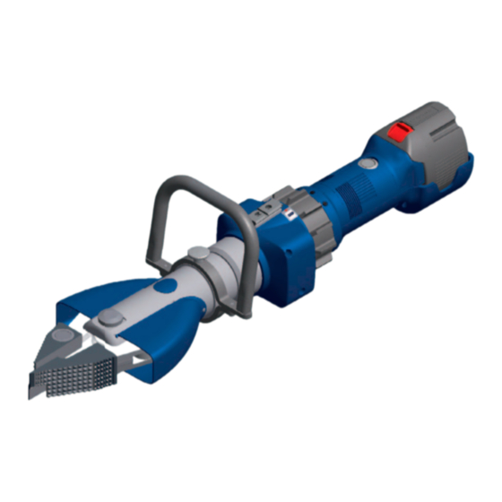
Page 11: Structure And Functions
4.2 Structure and functions 4.2.1 Illustration with combination tips 1 Star grip 2 Main switch 3 Quick exchange battery 4 Release button for battery 5 Handle (rotates 360°) 6 Locking bolt, pull up to unlock 7 Ventilation slots 8 Tool tips (combination snap-on tips) 9 Blade arms 10 Pivot bolt with secured nut... - Page 12 4.2.2 Blade arms without combi or door opening tips Blade arm Cutting edge Blade arm 4.2.3 Combination tips (snap-on tips) Please note! Use caution installing or emoving tips. Wear PPE (gloves) to avoid injury. Push button to release and automatically lock the tool tip Combination tip...
-
Page 13: Hydraulic Circuit Diagram
4.2.4 Door opening tips (snap-on tips) Please note! Use caution installing or removing tips. Wear PPE (gloves) to avoid injury. Push button to release and automatically lock the tool tip 3-Finger door opening tip 2-Finger door opening tip 4.2.5 Rotatable handle The handle can be rotated about 360 degrees with four set points every 90 degrees. -
Page 14: Operating Movement Controls
The symbols show the turning direction for opening and closing the tool tips. Star grip 5. Operation 5.1 Battery for StrongArm™ e100/le100 Commissioning Before initial operation, the battery of the rescue device must be fully loaded, using the external charger. -
Page 15: Operating The Star Grip
Worldwide safety guidelines pertaining to the speci c country must be observed and complied with. WARNING / CAUTION / PLEASE NOTE! The StrongArm™ e100/le100 device is not explosion-protected! When using the device in potentially explosive environments, the following must be excluded: - that the device could trigger an explosion. -
Page 16: Cutting
The following are to be worn when working with the rescue equipment: - protective clothing, - safety helmet with visor or protective goggles, - protective gloves - and, if necessary, ear protection - wear special protective clothing in case of extremely high temperatures Before operating the device, you should ensure that no participants or bystanders are at risk from the movements of the device or from ying fragments! Avoid unnecessary damage to property belonging to others or to objects not involved in the rescue or damage caused by... -
Page 17: Spreading
Unit [mm] / [in.] e100 / le100 / 0.08 ATTENTION! Where possible, avoid cutting through high-strength parts of the vehicle body (e.g. side impact protection). This may result in damage to the blades or to increased wear and tear! 6.3 Spreading... -
Page 18: Spreading Open Doors
(Illustration of the spreader tips as an example.) Working surface is too small, Tips get a safe grip. Work with the tips only. tips slip off. Do not damage the tool Only for increasing the size arms! of a gap (not suitable for spreading) 6.4 Spreading open doors The door opener tips are especially designed for using them for forced opening of locked... - Page 19 6.4.3 Operating safety instructions and application examples When operating rescue devices, wear • protective clothing • helmet with visor or goggles • protective gloves. WARNING / CAUTION / ATTENTION! During operation of this rescue device, parts of the object worked on with this device may break away and endanger people standing nearby.
-
Page 20: Accessories
7. Accessories 7.1 Battery Only HURST lithium-ion rechargeable batteries may be used to operate the device. These guarantee optimum performance and maximize the operating time of the device. NOTE: To ensure maximum operating time and maximum uptime, you must make sure that the battery is always fully charged before connecting it to a rescue device. -
Page 21: Battery Charger
7.2 Battery charger Only the battery charger from the HURST accessories list may be used for the lithium-ion batteries. This guarantees optimum charging and operating time for the battery. NOTE: Pay strict attention to the separate operating instructions for the battery charger. -
Page 22: Accessory Rail
Accessory rail with universal rail The accessory rail allows to attach the universal rail which is within the HURST scope of delivery and pre-installed on delivery. The design of the universal rail allows the attachment of various lights and a variable positioning of the lights. If not used, the rail can easily be removed. -
Page 23: Dismantling The Equipment / Deactivation Following Operation
8. Dismantling the equipment / deactivation following operation Once work has been completed, the device arms should be closed until the tips are only a few millimeters apart. This relieves the hydraulic and mechanical strain on the equipment. NOTE: Never store the device with fully closed arms or a fully retracted piston! By fully closing the arms, hydraulic pressure and mechanical tension may develop in the device. -
Page 24: Inspections Strongarm™ E100/Le100
9.1 Inspections StrongArm™ e100/le100 Inspections to be carried out: Visual Inspection StrongArm™ e100/le100 with cutting and spreading function • Opening width of the blade arms on the tips (see chapter "Technical data"), • General tightness (leaks), • Operability of the star grip - check the automatic return into middle position after release (deadman function), •... -
Page 25: Checking And Exchanging The Lter Element
9.3 Checking and exchanging the lter element The air suction lter is to be checked at least once a year or after use in a dusty environment. The lter can be checked from the outside if the battery is removed (see illustrations below). If the lter is severely contaminated, it will need to be replaced. -
Page 26: Repairs
10. Repairs 10.1 General information Service work may only be performed by the device manufacturer or by personnel trained by the device manufacturer and authorized HURST dealers. Only HURST spare parts may be used to replace all components (see spare parts list), as special tools and compliance with, assembly instructions, safety aspects and inspections are required (see also chapter “Maintenance and Servicing”). -
Page 27: Preventive Service
10.2 Preventive service 10.2.1 Care instructions The outside of the device should be cleaned with a damp cloth from time to time (not the electrical contacts in the connection slot, and on the battery). In addition, the metal surfaces are to coated with a suitable medium to counteract corrosion (not the electrical contacts in the connection slot, on the battery). - Page 28 10.3.2 Replacing the handle 1. Unscrew the two attachment screws with an Allen key. 2. Remove the lower part of the handle while holding the upper part. Then take off the upper part. 3. Position the new handle and hold it, while mounting the lower part with the attachment screws (use medium strength thread lock e.g.
- Page 29 2. Remove lock screw with an Allen key (2 mm / 0.08 in.). 3. Unscrew nut of pivot bolt ( wrench size 30) and remove bolt. 4. Remove retaining rings on both blade arm bolts and remove them. 5. Remove blade arms and replace with new ones. 6.
-
Page 30: Troubleshooting
11. Troubleshooting Fault Check Cause Solution Blades, spreader arms Battery fully Battery week Charge battery move slowly or jerkily charged? Battery defective Replace battery when operated Air in the hydraulic Repair by an system authorized dealer, by personnel specially trained by HURST, or by HURST itself Blades, spreader arms... -
Page 31: Technical Data
NOTE: The following tables contain only the technical data necessary for operation and storage. Further information about your device is available directly from HURST. Operating pressure: StrongArm™ e100/le100: 70 MPa / 10000 psi... -
Page 32: Strongarm™ E100/Le100
12.1 StrongArm™ e100/le100 Device type StrongArm™ e100 / le100 273100000 (e100 blue) Item number 273180000 (le100 black) [mm] 796 x 195 x 210 Dimensions (excluding battery) L x W x H [in.] 31.3 x 7.7 x 8.3 [mm] 215 mm... -
Page 33: Noise Emission
12.2 Noise emission Device type e100 / le100 Battery type used for device Lithium-ion Idling (measured at a distance of 1 m, [dB(A)] according to EN) Full load (measured at a distance of 1 m, [dB(A)] according to EN) Idling (measured at a distance of 4 m,... -
Page 34: Lighting (Optional Expansion Possibility)
13. Lighting (optional expansion possibility) The lighting unit is optional and not offered by HURST. The illustratioin shows a typical installation of a ashlight as an overview. Pay always attention to the separate instruction manual provided from the supplier or manufacturer to mount and operate your ashlight unit as intended. - Page 35 Rail clamp tensioning bolt Paddle switch Rail key Rail groove Universal rail (image as a sample) Attachment screws (hex socket head) NOTE: Pay also strict attention to the separate operating instructions for the light and take further details from it.
-
Page 36: Instructions Regarding Disposal
14. Instructions regarding disposal Please duly dispose of all packaging materials and removed items. Electrical equipment, accessories and packaging should always be disposed of in an environmentally compatible way. Only for EU countries: Do not dispose of electrical equipment with your household waste! According to the European Directive 2002/96/EC governing electrical and electronic waste and their application in national legislation, old electrical equipment must be separately collected and recycled in an environmentally compatible manner. -
Page 37: Notes
15. Notes... - Page 40 Please duly dispose of all packaging materials and removed items. HURST JAWS OF LIFE, INC A Unit of IDEX Corporation 711 N. Post Road Shelby, NC 28150 USA Phone: (704) 487-6961 Fax: (704) 487-7271 e-mail: contacthurst@idexcorp.com Made in USA e100_le100_manual_273100085_en.indd ©...
Need help?
Do you have a question about the le100 and is the answer not in the manual?
Questions and answers