Table of Contents
Advertisement
Quick Links
Instruction Manual
918
series
Powerig® Hydraulic Unit
Components Overview
Electrical Schematics
Electrical Enclosure (918-5)
Return Line (918)
Return Line (918-5)
Makers of Huck
January 18, 2017
Brand Fasteners, Tools & Accessories
HK786
Components Drawings
Kits and Accessories
, Marson
, Recoil
®
®
3
4
5
5
6
7
8
9
10-11
12-13
14
15
16
17-18
19
20
21
22-23
24
24
25
26
26
®
Advertisement
Table of Contents

Related Manuals for Arconic 918 Series

Summary of Contents for Arconic 918 Series
-
Page 1: Table Of Contents
Safety Instructions Description Specifications Instruction Manual Principle of Operation series Powerig® Hydraulic Unit Preparation for Use Checking and Adjusting Pressures Operating Instructions Maintenance Components Drawings Components Overview 10-11 Electrical Schematics 12-13 Hydraulic Diagram Hose & Control Cord Hook-up Combination Valve Service Kit Hydraulic Pumps 17-18 Front Bracket Assembly... - Page 2 918 series Powerig Hydraulic Units (HK786)
-
Page 3: Safety Instructions
918 series Powerig Hydraulic Units (HK786) Safety Instructions This instruction manual must be read, with particular 11. Release tool trigger if power supply is interrupted. attention to the following safety guidelines, by any person servicing or operating this equipment. 12. Tools are not to be used in an explosive environment unless specifically designed to do so. -
Page 4: Description
918 series Powerig Hydraulic Units (HK786) Description GENERAL three-pole main disconnect switch, three main line fuses, two The models 918 and 918-5 HUCK Powerig® Hydraulic Units transformer fuses, and terminals for power cable connection. are electrically operated hydraulic power sources designed to The Control/Transformer Compartment contains two operate Huck Installation Equipment. -
Page 5: Specifications
25.0 (63.5) 44.0 (111.8) 30.0 (76.2) 585 (265) 708 (321) 918-5 29.0 (73.7) 44.0 (111.8) 30.0 (76.2) 601 (272) 724 (328) 918 series Powerigs are intended for use in COOLER: Fan and radiator air/oil heat exchanger REMOTE CONTROL: 24 volt AC control circuit indoor factory environments. -
Page 6: Preparation For Use
918 series Powerig Hydraulic Units (HK786) Preparation for Use gallons) until fluid level is in middle of fluid level gauge. WARNINGS: 3. Remove plastic shipping plugs from PULL and RETURN Only a qualified electrician is to install the pressure ports of TOOL 1, TOOL 2, (and for 918-5: TOOL 3). -
Page 7: Checking And Adjusting Pressures
918 series Powerig Hydraulic Units (HK786) Checking & Adjusting Pressures WARNINGS: CAUTION: The following check must be Turn OFF the Powerig prior to connecting completed quickly. Sustained high pressure or disconnecting tools. If it is necessary to will cause premature wear on the unit. -
Page 8: Operating Instructions
918 series Powerig Hydraulic Units (HK786) Operating Instructions Before operating the Powerig® Hydraulic Unit, make sure unit has been prepared for service as described in P . Connect hoses and control cords as shown in c rEParation for onnEcting nStallation... -
Page 9: Maintenance
918 series Powerig Hydraulic Units (HK786) Maintenance WARNING: Only a qualified electrician Smear LUBRAPLATE 130AA, or hydraulic fluid, on O-rings and is to install the power cable, according other components when reassembling combination valve. to local electrical codes, and service the Follow Figure 7 for proper position of all components. -
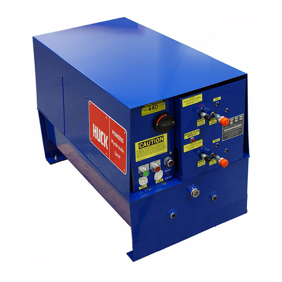
Page 10: Front View
918 series Powerig Hydraulic Units (HK786) 918 & 918-5 Front View Figure 1 110144 (918) Electrical Control Panel Assembly TOOL 1 Return TOOL 1 Pull (Figure `12) 114176 (918-5) Pressure Port Pressure Port Hood Indicator Light CAUTION 130650 Diconnect TOOL 2... - Page 11 918 series Powerig Hydraulic Units (HK786) Top View with Cover Removed Motor Oil Cooler 107754 Pump Grommet 502939 Suction Line Figure 2 506495 Assembly Pressure 107768 (220V & 440V) 110217 Front Bracket Assy Lines Pump-to-Motor Bulkhead 506635 Fan 101999 (must be replaced together) (380V) TOOL 1 &...
- Page 12 918 series Powerig Hydraulic Units (HK786) 918 & 918-5 Electrical Schematic Figure 3 NOTE: The graphics identified below appear in RED printing on the schematic.
- Page 13 918 series Powerig Hydraulic Units (HK786) 918-380 & 918-5/380 Electrical Schematic Figure 4 NOTE: The graphics identified below appear in RED printing on the schematic.
-
Page 14: Hydraulic Diagram
918 series Powerig Hydraulic Units (HK786) 918 & 918-5 Hydraulic Diagram Figure 5... -
Page 15: Hose & Control Cord Hook-Up
918 series Powerig Hydraulic Units (HK786) Typical Hose and Control Cord Hook-up Figure 6... -
Page 16: Combination Valve Service Kit
918 series Powerig Hydraulic Units (HK786) 120073 Combination Valve Service Kit Figure 7 Used on Combination Valve, P/N 119740 504475 O-Ring 107862 128287 504410 120074 504712 Idler Valve Setscrew Spring O-Ring O-Ring Spring Return Retainer Pressure Adjustment Idler Valve Pull... -
Page 17: Hydraulic Pumps
918 series Powerig Hydraulic Units (HK786) Hydraulic Pumps For parts identification, see Figures 8 & 9 on the 10. Remove six socket-head cap screws (Figure 8, Item 7) to following pages. remove the cover when replacing O-rings, seats, balls, or... - Page 18 918 series Powerig Hydraulic Units (HK786) Hydraulic Pumps (continued) POWERIG PUMP NO. TYPE 918, all voltages 110217 2-Port 918-5, all voltages 114200 3-Port Figure 8 5c 5b 5e 5d Exploded View of Split Flow Hydraulic Pump Figure 9 ITEM 918-5...
-
Page 19: Front Bracket Assembly
918 series Powerig Hydraulic Units (HK786) Front Bracket Assembly Figure 10... - Page 20 918 series Powerig Hydraulic Units (HK786) Electrical Enclosure Assembly 918-5 series Figure 11 1 2 3 12 13 VIEW B-B 123526 - Electrical Enclosure Assembly 918-5, Tool 3 VIEW A-A...
-
Page 21: Electrical Control Panel
918 series Powerig Hydraulic Units (HK786) Electrical Control Panel Assembly Figure 12 Part Number: 123912: 918, 918-5 123912-1: 918/550, 918-5/550 123912-2: 918-380 123912-3: 918/220... -
Page 22: Control Panel Wiring
918 series Powerig Hydraulic Units (HK786) Electrical Control Panel Wiring Figure 13 (Reference Figures 12 & 13a for layout) NOTES: 1. Some components are shown disproportionally larger for clarity of wiring. 2. For wiring of other voltages, see Figure 13a on the next page. - Page 23 918 series Powerig Hydraulic Units (HK786) Electrical Control Panel Alternate Wiring Figure 13a 220V Hook-up 380V Hook-up 190V Hook-up 550V Hook-up...
-
Page 24: Suction Line
918 series Powerig Hydraulic Units (HK786) 110135 Suction Line Assembly 918 & 918-5 Figure 14 507461 Pipe Nipple 106561 Suction Line Plate 503744 Elbow 505937 Pipe Nipple 106540 Strainer 503894 Check Valve 503745 Grommet 503743 Pipe Nipple 506496 Pipe Coupling... - Page 25 918 series Powerig Hydraulic Units (HK786) 123529 Return Line Assembly 918-5 Figure 16 Oil Filter 507089 Connects to TOOL 1 Combination Valve Connects to Connects to TOOL 3 TOOL 2 Combination Combination Valve Valve Grommet, Hose Coupling Note: The hose lengths listed below are suggested Filter Assembly, Return Line lengths.
- Page 26 918 series Powerig Hydraulic Units (HK786) Troubleshooting Always check the simplest possible cause of a malfunction first. Review the sections Preparation For Use and First-time Start-up. Check fuses, circuit breakers, control cord and connections, and hydraulic hose couplers. Where possible, substitute known good parts for suspected bad parts.
- Page 27 918 series Powerig Hydraulic Units (HK786) Limited Warranties Limited Lifetime Warranty on BobTail® Tools: Tooling, Part(s) and Other Items not manufactured by Huck: Huck International, Inc. warrants to the original purchaser that its BobTail® installation tools manufactured after 12/1/2016 HUCK makes no warranty with respect to the tooling, part(s), or other items manufactured by third parties.
- Page 28 Arconic Fastening Systems and Rings world-wide locations: AMERICAS EUROPE FAR EAST Kingston Operations...
Need help?
Do you have a question about the 918 Series and is the answer not in the manual?
Questions and answers