Advertisement
Quick Links
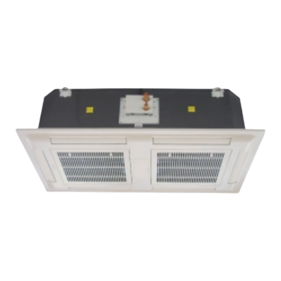
The Interklima Ceiling Mounted 4-way blow
cassettes are the ideal solution for
cooling/heating applications. They are
available in 9 models with nominal capacities
ranging from 2,7 kW to 16,2 kW in cooling
and 5,7 kW up to 15,1 kW in heating.
This series is ideal for any residential, light
commercial or commercial application where
floor and wall space is needed for fittings and
furniture, by being installed flush into every
ceilling with various air flow pattern flexibility
according to the room shape and layout.
II 09-12-18-24-25-30-35-40-50 CCV1
CEILING MOUNTED 4-WAY BLOW CASSETTE
COOLING/HEATING
TERMINAL UNIT
COOLING CAPACITY: 2,7 kW - 14,4 kW
HEATING CAPACITY: 2,7 kW - 15,1 KW
R 410a Rotary/Scroll
Features
Optimized design for R410a refrigerant.
Stylish.
Compact and lightweight.
Ideal for standardized false ceilings.
Low noise.
Auto restart after power failure.
Variable air flow distribution patterns.
Infrared remote control. (standard) or wired controller availability.
Master-Slave control capability.
RS-485 Port, for BMS communication.
Built-in condensate pump.
Easy access to all the components for maintenance
Standard filter for clean air.
Fresh air and branch ducting capability.
Self diagnosis.
Advertisement

Subscribe to Our Youtube Channel
Summary of Contents for Interklima II09CCV1
- Page 1 COOLING CAPACITY: 2,7 kW - 14,4 kW HEATING CAPACITY: 2,7 kW - 15,1 KW R 410a Rotary/Scroll Features The Interklima Ceiling Mounted 4-way blow Optimized design for R410a refrigerant. cassettes are the ideal solution for Stylish. cooling/heating applications. They are available in 9 models with nominal capacities Compact and lightweight.
- Page 2 NOMENCLATURE 1 Interklima I -X - XX - C - C-X-1 1 2 3 4 5 6 7 2 I- Indoor O- Outdoor 3 Model numbers (approx. capacity btu/h) 09-12-18-24-25-30-35-40-50 4 Unit type C- Cassette 5 Refrigerant type C- R410A...
-
Page 3: Table Of Contents
Contents 1. Technical Specifications 2. Outlook Drawings 3. Refrigerant Circuit Diagrams 4. Wiring Diagrams 5. Installation 6. Controller Instruction and Specifications 7. Service Interklima Dx Cassette Units II-IO CCV1 R410A / Rotary / Scroll... -
Page 4: Technical Specifications
Indoor side Flare Outdoor side Flare heating 20 o DB Refrigerant charge (5m) 0.85 0.90 1.28 1.70 indoor: outdoor: 7 o DB Pipe size OD Liquid 6 o WB Interklima Dx Cassette Units II-IO CCV1 R410A / Rotary / Scroll... - Page 5 Indoor side Flare 24 o WB Outdoor side Flare heating 1.65 3.30 20 o DB Refrigerant charge (5m) indoor: outdoor: 7 o DB Pipe size OD Liquid 6 o WB Interklima Dx Cassette Units II-IO CCV1 R410A / Rotary / Scroll...
- Page 6 Indoor side 24 o WB Flare Outdoor side heating 20 o DB Refrigerant charge (5m) 3.30 3.70 4.40 indoor: outdoor: 7 o DB Pipe size OD Liquid 6 o WB Interklima Dx Cassette Units II-IO CCV1 R410A / Rotary / Scroll...
-
Page 7: Outlook Drawings
Outlook drawings IO09/12CCV1 Interklima Dx Cassette Units II-IO CCV1 R410A / Rotary / Scroll... - Page 8 IO09CCV1 IO12CCV1 Interklima Dx Cassette Units II-IO CCV1 R410A / Rotary / Scroll...
- Page 9 IO18/24CCV1 Interklima Dx Cassette Units II-IO CCV1 R410A / Rotary / Scroll...
- Page 10 IO18CCV1 IO24CCV1 Interklima Dx Cassette Units II-IO CCV1 R410A / Rotary / Scroll...
- Page 11 II25/30/35/40/50CCV1 Interklima Dx Cassette Units II-IO CCV1 R410A / Rotary / Scroll...
- Page 12 IO25CCV/Y1 IO30/35CCV/Y1 Interklima Dx Cassette Units II-IO CCV1 R410A / Rotary / Scroll...
- Page 13 IO40/ 50CCY1 Interklima Dx Cassette Units II-IO CCV1 R410A / Rotary / Scroll...
-
Page 14: Refrigerant Circuit Diagrams
Refrigerant Circuit Diagram Interklima Dx Cassette Units II-IO CCV1 R410A / Rotary / Scroll... -
Page 15: Wiring Diagrams
Indoor Fan Compressor Remote Receiver Outdoor Fan Stepping Motor Outdoor Coil TEMP Sensor Stepping Motor High Pressure Protector Stepping Motor Low Pressure Protector JP10 Stepping Motor AUX EC Electric Heater Interklima Dx Cassette Units II-IO CCV1 R410A / Rotary / Scroll... - Page 16 Indoor Temp Sensor JP12 Indoor Coil TEMP Sensor JP13 Wall Pad JP14 Float Switch Compressor Outdoor Fan Outdoor Coil TEMP Sensor High Pressure Protector Low Pressure Protector AUX EC Electric Heater Interklima Dx Cassette Units II-IO CCV1 R410A / Rotary / Scroll...
- Page 17 IO09/12/18CCV1 (Outdoor Unit – 1 Phase) Interklima Dx Cassette Units II-IO CCV1 R410A / Rotary / Scroll...
- Page 18 IO24CCV1 (Outdoor Unit – 1 Phase) Interklima Dx Cassette Units II-IO CCV1 R410A / Rotary / Scroll...
- Page 19 Outdoor Fan Stepping Motor Outdoor Coil TEMP Sensor Stepping Motor High Pressure Protector Stepping Motor Low Pressure Protector JP10 Stepping Motor AUX EC Electric Heater JP11 Indoor Temp Sensor Interklima Dx Cassette Units II-IO CCV1 R410A / Rotary / Scroll...
- Page 20 Outdoor Fan Stepping Motor Outdoor Coil TEMP Sensor Stepping Motor High Pressure Protector Stepping Motor Low Pressure Protector JP10 Stepping Motor AUX EC Electric Heater JP11 Indoor Temp Sensor Interklima Dx Cassette Units II-IO CCV1 R410A / Rotary / Scroll...
- Page 21 Outdoor Fan Stepping Motor Outdoor Coil TEMP Sensor Stepping Motor High Pressure Protector Stepping Motor Low Pressure Protector JP10 Stepping Motor AUX EC Electric Heater JP11 Indoor Temp Sensor Interklima Dx Cassette Units II-IO CCV1 R410A / Rotary / Scroll...
- Page 22 Outdoor Fan Stepping Motor Outdoor Coil TEMP Sensor Stepping Motor High Pressure Protector Stepping Motor Low Pressure Protector JP10 Stepping Motor AUX EC Electric Heater JP11 Indoor Temp Sensor Interklima Dx Cassette Units II-IO CCV1 R410A / Rotary / Scroll...
- Page 23 IO25CCV1 (Outdoor - 1 Phase) IO30/35CCV1 (Outdoor – 1 Phase) Interklima Dx Cassette Units II-IO CCV1 R410A / Rotary / Scroll...
- Page 24 IO25CCY1 (Outdoor - 3 Phase) Interklima Dx Cassette Units II-IO CCV1 R410A / Rotary / Scroll...
- Page 25 IO30/35CCY1 (Outdoor - 3 Phase) Interklima Dx Cassette Units II-IO CCV1 R410A / Rotary / Scroll...
- Page 26 IO40/50CCY1 (Outdoor - 3 Phase) Interklima Dx Cassette Units II-IO CCV1 R410A / Rotary / Scroll...
-
Page 27: Installation
ñ This avoids over-flow in the drain pan, by allowing the pump fig.1 to drain any condensate water due to regulating valve losses when chiller is working. Operation limits ñ Power supply Volt Phase fig.2 Interklima Dx Cassette Units II-IO CCV1 R410A / Rotary / Scroll... - Page 28 B (mm.) and servicing operations. II-09/12 10 or more II-18/24/30/35/40/50 10 or more ñ Ensure there is sufficient space around the unit to service it. See Fig.5 fig.3 fig.5 Interklima Dx Cassette Units II-IO CCV1 R410A / Rotary / Scroll...
- Page 29 590 x 590: Dimensions for opening 616 x 280: Suspension Bolts MODELS II09/12/18/24CCV1 Fig. 6 Fig. 8 Fig.9 590 x 1120: Dimensions for opening 517.5 x 1047.5: Suspension Bolts MODELS II-25/30/35/40/50CCV1 Interklima Dx Cassette Units II-IO CCV1 R410A / Rotary / Scroll...
- Page 30 ñ Incline unit (Fig.10, Fig.11, Fig.13, Fig.14) and insert it into connections, check again that the unit is level. Fig. 13 Fig. 10 Fig. 14 Fig. 11 Fig.15 Fig.12 MODEL II-09/12/18/24CCV1 MODEL II 25/30/35/40/50CCV1 A (mm.) A (mm.) Interklima Dx Cassette Units II-IO CCV1 R410A / Rotary / Scroll...
- Page 31 ñ The flexible hose should be fitted into a 22 mm O/S º. polyvinyl tube and sealed. The drain must be installed with a downward slope. ñ On completion the drain line should be insulated II 18/24CCV1 Fig.16 II- 25/30/35/40/50CCV1 Interklima Dx Cassette Units II-IO CCV1 R410A / Rotary / Scroll...
- Page 32 TERMINAL BLOCK II-25/30/35/40/50CCV1 When the installation is completed, it is necessary to wrap connecting pipe with insulation to prevent leakage to ceiling tile. Interklima Dx Cassette Units II-IO CCV1 R410A / Rotary / Scroll...
- Page 33 You can fill the drainpan by pouring water through the external drainpan. If everything is correct, the water will be pushed out into the pipe work you have installed. If the compressor does not turn on, you Interklima Dx Cassette Units II-IO CCV1 R410A / Rotary / Scroll...
- Page 34 Order flanges (spigots) and blanking plates as accessories separately. MODEL Fig.26 II 25/30/35/40/50CCV1 1100 NOTE: - Branch duct flange (Optional part) - Fresh air duct flange (Optional part) - Blanking plate (Optional part) Interklima Dx Cassette Units II-IO CCV1 R410A / Rotary / Scroll...
- Page 35 3. Knock out the pre-cut hole. 4. Connect the flange on to the opening with º3 mm. x 12 mm. tapping screws. FRESH AIR DUCT DIMENSION Interklima Dx Cassette Units II-IO CCV1 R410A / Rotary / Scroll...
- Page 36 Be sure unit panels are securely in place prior to rigging. Therefore the cylinder must be equipped with a dip tube to Keep unit upright. Lift unit using slings. Use cardboard or padding Interklima Dx Cassette Units II-IO CCV1 R410A / Rotary / Scroll...
- Page 37 See refrigerant charging table. structure. Leave some slack in the refrigerant tubes between the structure and unit to absorb vibration. Refer to evaporator installation instructions for additional information. Interklima Dx Cassette Units II-IO CCV1 R410A / Rotary / Scroll...
- Page 38 - Open the low-pressure valve on the charge set slightly to air purge from the charge hose. - Refrigerant must be recovered. Don’t vent the Refrigerant to the atmosphere. Interklima Dx Cassette Units II-IO CCV1 R410A / Rotary / Scroll...
- Page 39 5. Disconnect the charge hose from the vacuum pump. - Vacuum pump oil. If the vacuum pump oil becomes dirty or depleted, replenish as needed. Interklima Dx Cassette Units II-IO CCV1 R410A / Rotary / Scroll...
- Page 40 Open Open (with charging cylinder) 4. Gas charging (Servicing) Open (with charging cylinder) 5. Pressure check (Servicing) Open Open 6. Gas releasing (Servicing) Open Open Open (with charging cylinder) Interklima Dx Cassette Units II-IO CCV1 R410A / Rotary / Scroll...
-
Page 41: Controller
Press the TIME-SET to increase the time by 1 minute step. At last, press the Clock Button again. 14. Reset Button Press it to restart remote LCD DISPLAY Interklima Dx Cassette Units II-IO CCV1 R410A / Rotary / Scroll... - Page 42 TIMEUP or DOWN button. After you change master unit parameters, press the enter button. The slaveunits parameters will change. Interklima Dx Cassette Units II-IO CCV1 R410A / Rotary / Scroll...
- Page 43 C, the post-heat will be activated, then when compressor and outdoor fan will be turned on. Ti<33 C, It will be terminated. b. Indoor runs at the same speed as indoor fan runs in pre-heat. Interklima Dx Cassette Units II-IO CCV1 R410A / Rotary / Scroll...
- Page 44 During protection: In COOL mode, outdoor unit stops, indoor fan runs at set speed. In DEHUMIDIFICATION mode, outdoor unit stops, indoor fan runs at low speed. Interklima Dx Cassette Units II-IO CCV1 R410A / Rotary / Scroll...
- Page 45 2 hours. The auxiliary electric heat is obsolete. outdoor fan runs 30% and stops 70% of the operation cycle. d. Changing of operation mode will cancel sleep mode. Interklima Dx Cassette Units II-IO CCV1 R410A / Rotary / Scroll...
- Page 46 If Tr<Ts-3∞C, indoor fan runs at high speed. The indoor unit will remain on. d. In HEAT mode, the fan speed cannot change until it has run at this speed over 30 seconds. Interklima Dx Cassette Units II-IO CCV1 R410A / Rotary / Scroll...
-
Page 47: Service
ñ Remove fixing screws of the drain pan fixture and remove condensate drain pan with care. The appliance are intended to be maintained by qualified service personnel and located at a level not less than 2.5m. Fig.19 Interklima Dx Cassette Units II-IO CCV1 R410A / Rotary / Scroll... - Page 48 Unit assembly II 09/12/18/24CCV1 II 25/30/35/40/50CCV1 Interklima Dx Cassette Units II-IO CCV1 R410A / Rotary / Scroll...
- Page 49 From outdoor coil outdoor coil Insulate TP-4 TP-3 TP-2 for accurate reading Insulate TP-1 for accurate reading Electronic From compressor thermometer discharge line Reversing valve (heating mode, solenoid de-energized) Fig.4 Interklima Dx Cassette Units II-IO CCV1 R410A / Rotary / Scroll...
- Page 50 Starting current (AMPS) 23 38 45 54 35 64 64 66 67 230V/1/50 64 105 97 110 OPERATION TEMPERATURE LIMITS Operation / Temperature Indoor DB ( Outdoor DB ( Cool Heat Interklima Dx Cassette Units II-IO CCV1 R410A / Rotary / Scroll...
- Page 51 16 Cover panel assembly 16-0 Receiver display 16-1 Receiver label sticker 16-2 Grille 16-3 Bolt (Left) 16-4 Bolt (Right) 16-5 Swing Louver 16-6 Stepping motor 16-7 Fan bearing 17 Wired wall pad Interklima Dx Cassette Units II-IO CCV1 R410A / Rotary / Scroll...
- Page 52 17 Cover Panel assembly 17-1 Grille 17-2 Receiver label sticker 17-3 Swing Louver 17-4 Bolt (Right) 17-5 Bolt (Left) 17-6 Stepping motor 17-7 Fan bearing 18 Wired wall pad Interklima Dx Cassette Units II-IO CCV1 R410A / Rotary / Scroll...
- Page 53 11.9008 2.8694 0.8876 11.3890 2.7697 0.8716 10.9023 2.674 0.8466 10.4393 2.5821 0.8223 9.9987 2.4939 0.7989 9.5794 2.4091 9.1801 2.3276 8.7999 2.2493 8.4377 2.174 8.0925 2.1017 7.7635 2.032 7.4498 1.9651 Interklima Dx Cassette Units II-IO CCV1 R410A / Rotary / Scroll...
-
Page 54: Troubleshooting
REPLACE BOTH SENSORS & CHECK PUMP SENSORS DAMAGED AND CONDENSED OR FLOAT SWITCH OR DRAINAGE SYSTEM WATER OVER FLOW REFRIGERANT LEAKAGE, BLOCKAGE OR SHORTAGE CHECK FOR GAS LEAKAGE, BLOCKAGE AND SHORTAGE. Interklima Dx Cassette Units II-IO CCV1 R410A / Rotary / Scroll... - Page 55 If the drain pump fails, the system will alarm with beep. Press reset button or any of the remote handset buttons, alarm will stop. d. If malfunction indicated by LED blinking. Turn off the unit and resolve the malfunction. Interklima Dx Cassette Units II-IO CCV1 R410A / Rotary / Scroll...
- Page 56 Interklima units comply with the European regulations that guarantee the safety of the product Specifications subject to change without notice INTERKLIMA PRODUCTS ARE DISTRIBUTED BY:...
Need help?
Do you have a question about the II09CCV1 and is the answer not in the manual?
Questions and answers