Advertisement
Quick Links
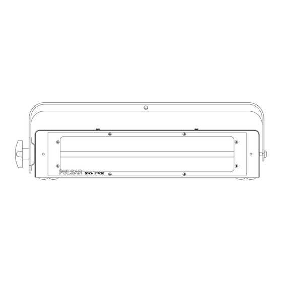
DEMON STROBE
SPECIFICATION
27800 Demon Strobe 200-240Volts
The most powerful of the Pulsar range of Strobes, the Demon Strobe
provides high power strobe lighting from a 1.5kW linear tube and a
linear parabolic reflector. It is fully dimmable and may be controlled by
a DMX/PMX Digital signal, 0-10V Analogue signal or its own internal
controls.
By using a Pulsar Masterpiece or Rainbow Strobe/Chaser to drive a
number of Demon Strobes, each fitted with a different colour filter, it
is possible to create the ultimate strobe display, where each frozen
image is captured in a different colour.
INSTALLATION
INSTALLATION AND SERVICE
out by suitably skilled and competent persons.
The Demon Strobe must be securely mounted, using the
M10 bolt, spring washer and wingnut provided, through the hole
located in the handle.
A safety chain of suitable length and strength (e.g. Pulsar part no.
60030/1) must be securely fixed between the safety chain fixing point
on the rear of the Strobe and the suspension point (mounting surface).
BACK PANEL CONNECTIONS
MAINS SUPPLY -
200-240 VAC, 50-60Hz, 10A nominal.
We recommend the use of a Residual Current Circuit
Breaker.
The mains cable should be fitted with a suitable approved and
rated plug.
Note: in some countries it is a requirement that such a plug be
fitted by a qualified electrician.
CABLE COLOURS
Green/Yellow
=
Brown
=
Live / Phase / Hot
Blue
=
Neutral
WARNING - THIS APPLIANCE MUST BE EARTHED
POWER SAVING TECHNIQUE -
with odd and even serial numbers to take power from the mains at
different points in time. So an even numbered unit plus an odd
numbered unit together on the same supply, only have a peak power
requirement 40% higher than one strobe - not double. Where a
number of Demon Strobes are used together on the same supply we
recommend you take advantage of this technique.
POWER SWITCH:
controls the power to the unit and provides 2 pole
overcurrent protection and isolation. 0 - OFF, 1 - ON.
STATUS INDICATORS:
Power On LED - When illuminated this indicates that the equipment
is connected to the supply and switched on.
Receiving Data LEDs - Indicate a digital signal (PMX/DMX) has been
received.
Data Error LED - indicates the last signal received was not
recognised. Errors can often occur if the DMX line is not terminated.
Unlike DMX, PMX may be branched and needs no termination.
must only be carried
Earth / Ground
We have arranged for units
A double pole circuit breaker
CONTROL SIGNALS:
Control of the Strobe may be from:
a digital controller using the DMX512 or PMX protocols (e.g.
Masterpiece); an analogue controller (e.g. Desk, Rock Desk) or a
strobe controller (e.g. Rainbow Strobe/Chaser).
Note: if more than one control signal type is used, the highest level will
take priority.
DIGITAL CONTROL SIGNALS:
are provided for the digital inputs.
PMX SIGNAL AND LV SUPPLY DMX SIGNAL AND LV SUPPLY
Pin 1 =
Chassis Earth - Screen Pin 1 =
Pin 2 = Signal
Pin 3 = Signal Earth
Pin 4 = no connection
Pin 5 = Low Voltage Supply Out
male XLR only
Notes:
Pins 4 and 5 are occasionally used by other manufacturers for data.
We recommend the use of 2 core plus screen cable, leaving pins 4
and 5 open circuit, to connect to this type of equipment. However, the
Low Voltage Supply on pin 5 of the male XLR is limited to cause no
harm to such equipment.
The end of the DMX line must always be terminated with a 100 ohm
resistor connected between Signal+ (pin3) and Signal- (pin2). This
resistor can conveniently be mounted in a 5 pin XLR plug (Pulsar Part
No. 21750.4) which should be inserted in the last device on the DMX
line.
The digital start address is set with these
switches, the valid range being from 001 to 510.
The addressing is in blocks of 3, for example:
001 (510) - Trigger
002 (511) - Speed
003 (512) - Brightness
0-10V REMOTE CONTROL INPUTS:
Two 8 pin DIN sockets (in/thru) and a jack socket are provided.
The 0-10V DIN Sockets are cross connected to allow a 6 channel
desk to control two strobes using only one 8 channel DIN cable (see
Accessories). Further Strobes may also be controlled in this manner
with the odd Strobes being controlled by channels 1-3 and the even
Strobes by channels 4-6.
Two 5 pin XLR sockets (in/thru)
Chassis Earth - Screen
Pin 2 = Signal -
Pin 3 = Signal +
Pin 4 = no connection
Pin 5 = Low Voltage Supply Out
male XLR only
I
N
S
T
R
U
C
T
I
O
N
S
Advertisement

Subscribe to Our Youtube Channel
Related Manuals for Pulsar Demon Strobe

Summary of Contents for Pulsar Demon Strobe
-
Page 1: Back Panel Connections
(e.g. Rainbow Strobe/Chaser). Note: if more than one control signal type is used, the highest level will The most powerful of the Pulsar range of Strobes, the Demon Strobe take priority. provides high power strobe lighting from a 1.5kW linear tube and a linear parabolic reflector. - Page 2 New tubes can be obtained from your positive going edge of the pulse will fire the Strobe at the brightness dealer or directly from Pulsar. Take care not to handle the Quartz set by the Digital or 0-10V brightness channel or the internal envelope of the tube - if touched it must be cleaned with alcohol.
Need help?
Do you have a question about the Demon Strobe and is the answer not in the manual?
Questions and answers