Table of Contents
Advertisement
Quick Links
C-MONSTER GATEWAY
INSTRUCTIONS
INCLUDED HARDWARE:
A.
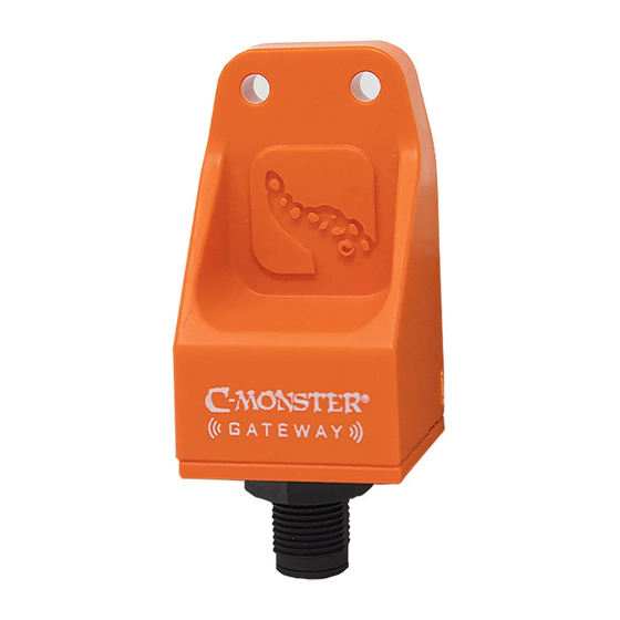
(1) NMEA GATEWAY Unit
B.
(2) #8 3/4" Gateway Screws
C.
(1) #10 1-1/4" T-Connector Screw
D.
(1) Pairing Magnet
E.
(1) NMEA Drop Cable
F.
(1) T-Connector
Our NMEA 2000 GATEWAY is only for users who:
•
Have NMEA 2000 backbone installed in vessel
•
Have a LOWRANCE
unit installed in vessel
®
IMPORTANT:
Before proceeding, ensure your Lowrance® unit is running software
version 19.1 or later. The GATEWAY will not work with earlier versions.
Visit downloads.lowrance.com to download most recent software.
INSTALLATION
STEP 1: Use the mounting parameters listed below to select appropriate mounting location:
•
Mount where GATEWAY can be seen and touched with Pairing Magnet (D).
•
For best performance do not mount on metal surfaces or within 6" of large metal objects.
•
For longer vessels, centrally mount between all paired devices.
•
Make sure mounting location is close enough to reach existing NMEA Backbone.
•
GATEWAY Unit (A) MUST be mounted vertically and upright. FIG 1
STEP 2: Use supplied Template to mark and drill Mounting Holes. FIG 1
STEP 3: Drill Mounting Holes using a 7/64" Drill Bit.
STEP 4: Line GATEWAY Unit (A) up with Mounting Holes and install (2) GATEWAY Screws
(B) using a Phillips-Head Screwdriver. FIG 1
STEP 5: Screw Drop Cable (E) into bottom of GATEWAY (A). FIG 2
STEP 6: Screw Drop Cable (E) into T-Connector (F) and attach T-Connector (F)
to the rest of the NMEA 2000 backbone.
NOTE:
If T-Connector is at the end of the NMEA backbone, a terminator cap must be added to seal it.
STEP 7: Hold T-Connector (F) flush with mounting surface. Mark hole with fine-tip marker
and drill hole with 9/64" drill bit.
STEP 8: Line T-Connector (F) up with mounting holes and install T-Connector Screw (C)
using a Phillips-Head Screwdriver.
NOTE:
Secure any loose or excess wires with Zip-Ties.
Need help? Contact our Customer Service Team at 1 + 813.689.9932 Option 2
INSTALLATION TOOLS:
•
Electric Drill
•
9/64" Drill Bit
•
7/64" Drill Bit
•
Phillips-Head Screwdriver
•
Zip-Ties
B
F
A
C
D
Mounting Holes/
UP
Figure 1
E
NMEA Drop
Screws (B)
Cable (E)
Screws (B)
Figure 2
Advertisement
Table of Contents

Related Manuals for Power-Pole C-MONSTER

Summary of Contents for Power-Pole C-MONSTER
- Page 1 C-MONSTER GATEWAY INSTRUCTIONS INCLUDED HARDWARE: INSTALLATION TOOLS: • (1) NMEA GATEWAY Unit Electric Drill • (2) #8 3/4” Gateway Screws 9/64” Drill Bit • (1) #10 1-1/4” T-Connector Screw 7/64” Drill Bit • (1) Pairing Magnet Phillips-Head Screwdriver • (1) NMEA Drop Cable...
- Page 2 LED on GATEWAY (A) will blink. STEP 2: Follow FIG 3-7. STEP 3: Tap Pairing Magnet (D) to C-Monster Logo on GATEWAY Unit (A). The LED will be solid. STEP 4: Quickly press and release the Program Button on CHARGE™. When paired, GATEWAY LED will blink.
- Page 3 The device calculation of the LEN was determined based on an operating voltage of 9 VDC. 9010 Palm River Road, Tampa, Florida 33619 phone 813.689.9932 • fax 813.689.8883 • power-pole.com ©2020 all rights reserved. Power-Pole Shallow Water Anchor U.S. Patent No. 6,041,730...
Need help?
Do you have a question about the C-MONSTER and is the answer not in the manual?
Questions and answers