
Related Manuals for STEMMER IMAGING Gardasoft PP500

Summary of Contents for STEMMER IMAGING Gardasoft PP500
- Page 1 PP500 LED Lighting Controllers Issue 020 User manual www.gardasoft.com WWW.STEMMER-IMAGING.COM...
- Page 2 PP500 LED lighting controllers - User Manual Copyright and disclaimer notice Except as prohibited by law: All hardware, software and documentation is provided on an ‘as is’ basis. This information is for guidance only. Installers must perform their own risk assessment specific to each installation.
-
Page 3: Table Of Contents
PP500 LED lighting controllers - User Manual Contents Getting started Safety Heat Electrical General Installation guidance (disclaimer) Sicherheit Wärme Elektrik Allgemein Installationsanleitung (Haftungsausschluss) Sécurité Chaleur Électricité Généralités Guide d'installation (clause de non-responsabilité) General description Output modes 5.1.1 Continuous 5.1.2 Pulsed 5.1.3 Switched Triggers Flags... - Page 4 PP500 LED lighting controllers - User Manual — — WWW.STEMMER-IMAGING.COM WWW.STEMMER-IMAGING.COM...
-
Page 5: Getting Started
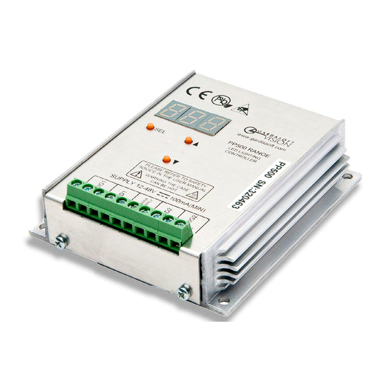
PP500 LED lighting controllers - User Manual Getting started This user manual describes the setting up and operation of the PP500 and PP500F lighting controllers. References to the PP500 apply to both except where noted. The PP500 is a channel lighting controller that provides 2 Amps continuously or 10 Amps pulsed. -
Page 6: Safety
PP500 LED lighting controllers - User Manual Safety Read this before using the PP500. Always observe the following safety precautions. If in doubt, contact your distributor or Gardasoft Vision. The following symbols mean: Warning: Read instructions to understand possible hazard Warning: Surface may get hot. -
Page 7: General
PP500 LED lighting controllers - User Manual 60335-1, IEC 61010-1, IEC61558-1,-2,-16. The PSU may also be approved to equivalent or superior safety standards. Any energised conductors derived from mains electricity must also have Safety Extra Low Voltage (SELV) output. Refer to for allowable voltage lim- its. -
Page 8: Sicherheit
PP500 LED lighting controllers - User Manual Sicherheit Bitte lesen Sie vor Verwendung des PP500 diese Informationen. Beachten Sie immer die folgenden Sicherheitshinweise. Wenden Sie sich im Zweifelsfall an Ihren Händler oder Gardasoft Vision. Die folgenden Symbole haben die folgende Bedeutung: Warnung: Lesen Sie die Hinweise, um eine mögliche Gefahr zu verstehen. -
Page 9: Allgemein
PP500 LED lighting controllers - User Manual getrennt sein und gegen Kurzschlüsse und Überlastungen geschützt sein. Wir empfehlen die Verwendung eines Netzgeräts, das den Ausgangsstrom durch konstruktive Maßnahmen, durch Einstellen der Stromgrenze an der Versorgung (wenn möglich) oder durch einen Überstromschutz auf den geeigneten Nennstrom der Steuerung begrenzt. -
Page 10: Installationsanleitung (Haftungsausschluss)
PP500 LED lighting controllers - User Manual Das PP500 darf nicht in Anwendungen eingesetzt werden, bei denen es durch einen Ausfall des Geräts zu einer Gefahr für die Gesundheit von Personen oder zur Beschädigung anderer Geräte kommen könnte. Wenn das Gerät in einer anderen als der vom Hersteller vorgesehenen Weise verwendet wird, kann die Schutzvorrichtung des Geräts beeinträchtigt werden. -
Page 11: Sécurité
PP500 LED lighting controllers - User Manual Sécurité Lisez ce document avant d'utiliser le PP500. Respectez les mesures de sécurité suivantes en toutes circonstances. En cas de doute, contactez votre distributeur ou Gardasoft Vision. Les symboles ci-dessous auront la signification suivante: Attention: Lisez les instructions pour comprendre quels sont les risques éventuels. -
Page 12: Généralités
PP500 LED lighting controllers - User Manual surcharges. Nous recommandons d'utiliser un boîtier d'alimentation qui limite le courant de sortie de l'appareil à la valeur nominale appropriée du contrôleur, en réglant la limite de courant sur l'alimentation (si possible) ou via la protection contre les surcharges. Le boîtier d'alimentation doit être approuvé... -
Page 13: Guide D'installation (Clause De Non-Responsabilité)
PP500 LED lighting controllers - User Manual Si l'équipement est utilisé autrement qu'aux fins prévues par le fabricant, la protection offerte par l'équipement pourrait en être altérée. Guide d'installation (clause de non-responsabilité) Ces informations sont seulement à titre indicatif. Les installateurs doivent effectuer leur propre évaluation des risques, pour chaque installation. -
Page 14: General Description
PP500 LED lighting controllers - User Manual General description The PP500 current controller provides repeatable intensity control of LED lighting for machine vision applications. It includes the power supply, intensity control, timing and triggering functions required for machine vision systems. LED lighting needs a constant current supply as small variations in voltage can cause large variations in light output. -
Page 15: Switched
PP500 LED lighting controllers - User Manual 5.1.3 Switched In switched mode, you can use a trigger input to switch the output current on and off. The output is enabled only when the input has a voltage on it. Triggers There are two trigger inputs, as summarised in the table below. Mode Trigger input Output... -
Page 16: Mechanical Fixing
PP500 LED lighting controllers - User Manual Mechanical fixing The PP500 can be mounted onto a flat surface using the M4 clearance mounting holes in the corners of the base or the M4 threaded holes in the centre, see the diagram below. Note: If you choose to mount the PP500 using the threaded holes, ensure no more than 6mm of thread can be screwed in. - Page 17 PP500 LED lighting controllers - User Manual To avoid a fire hazard, consider the implications of overheating in the unlikely event of a fault in the PP500. The power dissipation in a fault condition is approximately given by the sum of the following for the two channels: ) x I Where:...
-
Page 18: Pp500 Heat Output
PP500 LED lighting controllers - User Manual PP500 heat output The PP500 controller has a linear circuit to produce constant current output. This section explains how to calculate the heat output from the PP500 and what measures you can take to manage it. Heat output per channel For a continuous output current, the heat output is given by: Heat output = I... - Page 19 PP500 LED lighting controllers - User Manual Turn the light off when not needed. If you do not have precise timing of when the camera will trigger, you can use switched mode to switch the output off or on depending on the trigger input Reduce the output current if possible.
-
Page 20: Connections
PP500 LED lighting controllers - User Manual Connections All connections to the PP500 are made on screw terminals at one end of the case (see below). The screw terminals have the following connections: Screw terminal ID Function TRIG1– Channel 1 trigger input TRIG1+ LED1+ Channel 1 lighting output... -
Page 21: Power Supply
PP500 LED lighting controllers - User Manual below 1V, a logic 0. A logic 1 signal will sink approximately 3mA at any voltage from 3V to 24V. Power supply Refer to Section 2.2, Electrical Section 3.2, Elektrik, or Section 4.2, Électricité) for important guidance on selecting a power supply for your PP500. -
Page 22: Front Panel Configuration
PP500 LED lighting controllers - User Manual Front panel configuration Using the front panel keypad, you can set the configuration for each channel and set a keylock code so unauthorised users cannot change any settings. Startup On power up, the PP500 displays for five seconds followed by 8.8.8. -
Page 23: Setting Up Continuous Output
PP500 LED lighting controllers - User Manual The PP500 displays a pattern of alternating horizontal bars when the light is operating normally. If you power cycle the controller, it will resume with the same settings. Other displays are shown for channel 2 connected, and channels 1 and 2 connected. -
Page 24: Setting Up Switched Output
PP500 LED lighting controllers - User Manual Use the p and q buttons to select SCo and press the SEL button. bri is displayed. Press the SEL button. Use the p and q buttons to set the intensity from 1% to 99.9%, and press the SEL button. Your PP500 is ready to use. -
Page 25: Setting Up Pulsed Operation
PP500 LED lighting controllers - User Manual Use the p and q buttons to select SOn and press the SEL button. bri is displayed. Press the SEL button. Use the p and q buttons to set the intensity from 1% to 99.9%, and press the SEL button. Your PP500 is ready to use. - Page 26 PP500 LED lighting controllers - User Manual Use the p and q buttons to select SPu and press the SEL button. bri is displayed. Press the SEL button. Use the p and q buttons to set the intensity from 1% to 999%, and press the SEL button. deL is displayed.
-
Page 27: Setting Pulse Delay And Width Times
PP500 LED lighting controllers - User Manual Your PP500 is ready to use. Setting pulse delay and width times When the PP500 displays numeric values you can change, the right hand digit flashes. You can then use the p and q buttons to set the required value. - Page 28 PP500 LED lighting controllers - User Manual Use the p and q buttons to select the desired value. Press the SEL button. Use the p and q buttons to select E-4 to enter values from 0.1ms to 99.9ms in steps of 0.1ms. Press the SEL button.
- Page 29 PP500 LED lighting controllers - User Manual Use the p and q buttons to select E-6 to enter values from 20μs to 980μs in steps of 20μs using a PP500, or 1μs to 999μs in steps of 1μs using a PP500F. Press the SEL button.
-
Page 30: Reference Information
PP500 LED lighting controllers - User Manual Reference information 10.1 Timings Switched mode: The maximum delay from a trigger input changing to the output current being turned on or off is 10μs. Pulse Mode: For the PP500F the minimum pulse delay is about 4μs. 10.2 Specifications Parameter Value... -
Page 31: 10.3 Error Codes
PP500 LED lighting controllers - User Manual 10.3 Error codes Error Reason number Internal power dissipation is too high. Output turned off. Output current to lighting is too low. There is not enough supply voltage for the requested output current. The output is short circuit. The voltage required for the lighting has increased too much. - Page 32 PP500 LED lighting controllers - User Manual Issue 020 - January 2018 © Copyright 2002 -2018 Gardasoft Vision Ltd Gardasoft LLC Gardasoft Vision Ltd Oak Ridge Road Trinity Court Weare Buckingway Business Park New Hampshire Cambridge CB24 4UQ UK 03281 USA tel: +44 1954 234970 tel: +1 603-657-9026 fax: +44 1954 231567...
Need help?
Do you have a question about the Gardasoft PP500 and is the answer not in the manual?
Questions and answers