
Related Manuals for Caleffi solar iSolar 2

Summary of Contents for Caleffi solar iSolar 2
- Page 1 Mounting Connection Operation Troubleshooting Examples Thank your for buying this product. Read this manual carefully to get the best perfomance from this unit.
-
Page 2: Table Of Contents
Declaration of conformity We, CALEFFI NORTH AMERICA, Inc., declare under our sole responsibility that Subject to change without prior no- our product iSolar 2 complies with the following standards: tice. Errors excepted EN 55 014-1 EN 60 730-1... -
Page 3: Technichal Data And Overview Of Functions
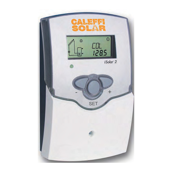
• pump speed control, solar ope- rating hours counter Scope of delivery: The iSolar 2 is a controller for stan- dard solar thermal systems. It provi- 1 x iSolar 2 des a clear operating concept and is... - Page 4 Examples iSolar 2 Standard solar systems For detailed connection diagrams see chapter 1.
-
Page 5: Installation
Installation WARNING! display Always switch-off power supply and 1.1 Mounting disconnect the controller from the mains before opening the housing! The unit must only be located in dry interior locations. It front cover is not suitable for installation in hazardous locations and should not be placed close to any electromagnetic fields. -
Page 6: Data Communication / Bus
1.2.1 Data communication / Bus The controller comes with a VBus for data communication ® and energy supply of external modules. The connection is effected with optional polarity at the clamps marked with„VBus “. Via this data Bus you can install one or more ®... -
Page 7: Operation And Function
Operation and function 2.1 Buttons for adjustment The controller is operated via the 3 push buttons below the display. The forward-button (1) is used for scrolling forward through the display menu or to increase the adjustment va- lues. The backward-button (2) is similarly used for scrolling backwards and reducing values. -
Page 8: System Screen
2.2.3 System screen The system screen (active arrangement) shows the scheme which has been selected. The screen consists of several system component symbols, which are - depending on the current status of the system - either flashing, permanently shown or „hidden“. system screen sensors tank top sensor... -
Page 9: Commissioning
3. Commissioning When the controller is commissionend for the first time, the arrangement has to be selected first 1. Switch on power supply. During the initialisation phase, the operating control lamp flashes red and green. After Operation control lamp initialisation, the controller is in the automatic mode with typical settings. -
Page 10: Control Parameter And Display Channels
Control parameters and display channels 4.1 Overview of channels Legend: Only if the option heat quantity measurement is activated Corresponding channel is available. (OHQM), will the corresponding channel be available. Corresponding channel is available when the corresponding Only if the option heat quantity measurement is deactiva- option is enabled ted (OHQM), will the corresponding channel be available. -
Page 11: Display Channels
4.1.1 Collector temperature Display of the current collector temperature. COL: Collector temperature • COL : collector temperature (1-collector system) display range: -40 ... +482 °F 4.1.2 Tank temperatures Display of the current tank temperature. TST,TSTL,TSTU: Tank temperatures • TST : tank temperature (1-tank system) Display range: -40 ... -
Page 12: Adjustment Channels
4.1.7 Heat quantity measurement option OHQM:Heat quantity Heat quantity measurement is possible if a flowmeter is measurement used. For this purpose, the heat quantity measurement Adjustment range: OFF ... ON option (OHQM) has to be enabled. Factory setting: OFF The flow rate should be read from the flowmeter (l/min) FMAX: and has to be adjusted in the channel FMAX. - Page 13 4.1.8 ∆T -regulation DT O: This function is a standard differential control. If the switch- Switch-on temperature diff. on differential is reached (DT O), the pump is operated. The Adjustment range: pump runs at 100% speed for 10 seconds. After this period, 2,0 ...
- Page 14 4.1.10 Collector emergency shutdown If the adjusted collector emergency shutdown temperature temperature (EM) is exceeded, the controller will switch off the solar pump (R1) in order to protect the system against overheating (collector emergency shutdown). The factoring setting is 285 °F but it can be changed within the adjustment range of Collector emergency shut- 230 ...
- Page 15 4.1.14 Recooling function If the adjusted maximum tank temperature (S MX) is reached, the controller keeps the solar pump running in OREC: order to prevent the collector from being overheated. recooling function option The tank temperature may increase but only up to 203 °F Adjustment range: (emergency shutdown of the tank).
- Page 16 4.1.16 Pump speed control A relative minimum pump speed is allocated to the output nMN: R1 via the adjustment channel nMN. Pump speed control Attention: Adjustment range: 30 ... 100 Factory setting: 40 When loads which are not speed controlled (e.g. valves) are used, the value must be changed to 100 % in order to deactivate pump speed control.
-
Page 17: Troubleshooting
5. Troubleshooting fuse T4A If a malfunction occurs, a message is displayed in the display of the controller: Warning symbol Operating control lamp Operating control lamp off Operating control lamp flashes red. The symbol are shown. Sensor fault. An error code instead of Check the power supply a temperature is shown on the sensor display channel. -
Page 18: Various
5.1Various: Pump is overheated, but no heat transfer from the colle- Pump starts for a short moment, switches-on/off ctor to the tank, flow and return have the same tempe- again,etc. rature; perhaps also bubble in the lines Air in the system? Is the temperature diffe- Vent the system;... - Page 19 Tanks cool down at night. Check the non-return Further pumps which are valve in warm water cir- connected to the solar culation- o.k. tank must also be che- cked. Does the collector circuit pump run in the night? Check controller. Clean or replace The gravity circu lation in the circulation line is too...
-
Page 20: Accessory
6. Accessory Sensors Our product range includes high-precision platin tempe- rature sensors, flatscrew sensors, outdoor temperature sensors, indoor temperature sensors, cylindrical clip-on sensors and irradiation sensors, also as complete sensors with immersion sleeve. Overvoltage protection device In order to avoid overvoltage damage at collector sensors (e.g.
Need help?
Do you have a question about the iSolar 2 and is the answer not in the manual?
Questions and answers