Advertisement
Available languages
Available languages
Quick Links
Download this manual
See also:
User Manual
Version 1.0
Published September 2014
Copyright©2014 ASRock INC. All rights reserved.
Copyright Notice:
No part of this documentation may be reproduced, transcribed, transmitted, or
translated in any language, in any form or by any means, except duplication of
documentation by the purchaser for backup purpose, without written consent of
ASRock Inc.
Products and corporate names appearing in this documentation may or may not
be registered trademarks or copyrights of their respective companies, and are used
only for identiication or explanation and to the owners' beneit, without intent to
infringe.
Disclaimer:
Speciications and information contained in this documentation are furnished for
informational use only and subject to change without notice, and should not be
constructed as a commitment by ASRock. ASRock assumes no responsibility for
any errors or omissions that may appear in this documentation.
With respect to the contents of this documentation, ASRock does not provide
warranty of any kind, either expressed or implied, including but not limited to
the implied warranties or conditions of merchantability or itness for a particular
purpose.
In no event shall ASRock, its directors, oicers, employees, or agents be liable for
any indirect, special, incidental, or consequential damages (including damages for
loss of proits, loss of business, loss of data, interruption of business and the like),
even if ASRock has been advised of the possibility of such damages arising from any
defect or error in the documentation or product.
his device complies with Part 15 of the FCC Rules. Operation is subject to the following
two conditions:
(1) this device may not cause harmful interference, and
(2) this device must accept any interference received, including interference that
may cause undesired operation.
CALIFORNIA, USA ONLY
he Lithium battery adopted on this motherboard contains Perchlorate, a toxic substance
controlled in Perchlorate Best Management Practices (BMP) regulations passed by the
California Legislature. When you discard the Lithium battery in California, USA, please
follow the related regulations in advance.
"Perchlorate Material-special handling may apply, see www.dtsc.ca.gov/hazardouswaste/
perchlorate"
ASRock Website: http://www.asrock.com
Advertisement

Subscribe to Our Youtube Channel
Related Manuals for ASROCK Fatal1ty Z97M Killer Series


Summary of Contents for ASROCK Fatal1ty Z97M Killer Series
-
Page 1: Copyright Notice
(including damages for loss of proits, loss of business, loss of data, interruption of business and the like), even if ASRock has been advised of the possibility of such damages arising from any defect or error in the documentation or product. - Page 2 he terms HDMI™ and HDMI High-Deinition Multimedia Interface, and the HDMI logo are trademarks or registered trademarks of HDMI Licensing LLC in the United States and other countries. Manufactured under license under U.S. Patent Nos: 5,956,674; 5,974,380; 6,487,535; 7,003,467 & other U.S. and worldwide patents issued & pending. DTS, the Symbol, & DTS and the Symbol together is a registered trademark &...
- Page 3 Fatal1ty Story Who knew that at age 19, I would be a World Champion PC gamer. When I was 13, I actually played competitive billiards in professional tournaments and won four or ive games of guys who played at the highest level. I actually thought of making a career of it, but at that young age situations change rapidly.
- Page 4 LIVIN’ LARGE Since my irst big tournament wins, I have been a “Professional Cyberathlete”, traveling the world and livin’ large with lots of International media coverage on outlets such as MTV, ESPN and a 60 Minutes segment on CBS to name only a few. It's unreal - it's crazy. I’m living a dream by playing video games for a living.
-
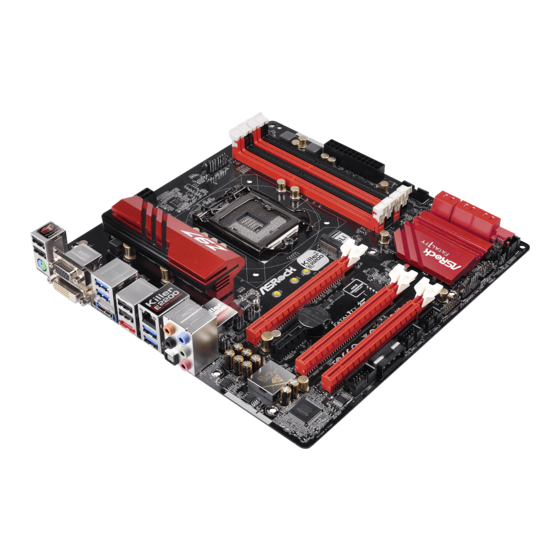
Page 5: Motherboard Layout
Fatal1ty Z97M Killer Series Motherboard Layout CPU_FAN2 CPU_FAN1 ATX12V1 USB 3.0 Top: T: USB2 RJ-45 B: USB3 Killer E2200 PWR_FAN1 CHA_FAN2 NUT4 NUT3 NUT2 NUT1 Z97M Killer PCIE1 CMOS Battery PCIE2 64Mb Purity FATAL BIOS Sound 2 Intel Intel PCIE3... - Page 6 No. Description ATX 12V Power Connector (ATX12V1) CPU Fan Connector (CPU_FAN2) CPU Fan Connector (CPU_FAN1) 2 x 240-pin DDR3 DIMM Slots (DDR3_A1, DDR3_B1) 2 x 240-pin DDR3 DIMM Slots (DDR3_A2, DDR3_B2) ATX Power Connector (ATXPWR1) USB 3.0 Header (USB3_4_5) SATA3 Connector (SATA3_0) SATA3 Connector (SATA3_3) SATA3 Connector (SATA3_1) SATA3 Connector (SATA3_4)
- Page 7 Fatal1ty Z97M Killer Series I/O Panel No. Description No. Description Fatal1ty Mouse Port (USB0) Front Speaker (Lime)** USB 2.0 Port (USB1) Microphone (Pink) D-Sub Port Optical SPDIF Out Port USB 3.0 Ports (USB3_01) USB 3.0 Ports (USB3_23) USB 2.0 Ports (USB23)
- Page 8 * here are two LEDs on each LAN port. Please refer to the table below for the LAN port LED indications. ACT/LINK LED SPEED LED LAN Port Activity / Link LED Speed LED Status Description Status Description No Link 10Mbps connection Blinking Data Activity Orange...
-
Page 9: Chapter 1 Introduction
If you require technical support related to this mother- board, please visit our website for speciic information about the model you are using. You may ind the latest VGA cards and CPU support list on ASRock’s website as well. ASRock website http://www.asrock.com. - Page 10 (Socket 1150) • Digi Power design • 8 Power Phase design • Supports Intel® Turbo Boost 2.0 Technology • Supports Intel® K-Series unlocked CPUs • Supports ASRock BCLK Full-range Overclocking • Intel® Z97 Chipset • Dual Channel DDR3 Memory Technology Memory • 4 x DDR3 DIMM Slots...
- Page 11 • 7.1 CH HD Audio with Content Protection (Realtek ALC1150 Audio Audio Codec) • Premium Blu-ray Audio support • Supports Surge Protection (ASRock Full Spike Protection) • Supports Purity Sound - Nichicon Fine Gold Series Audio Caps - 115dB SNR DAC with Diferential Ampliier - TI®...
- Page 12 • 1 x HDMI Port • 1 x Optical SPDIF Out Port • 1 x eSATA Connector • 3 x USB 2.0 Ports (Supports ESD Protection (ASRock Full Spike Protection)) • 1 x Fatal1ty Mouse Port (USB 2.0) (Supports ESD Protection (ASRock Full Spike Protection)) • 4 x USB 3.0 Ports (Supports ESD Protection (ASRock Full...
- Page 13 • Microsot® Windows® 10 64-bit / 8.1 32-bit / 8.1 64-bit / 8 32- bit / 8 64-bit / 7 32-bit / 7 64-bit • FCC, CE, WHQL Certiica- • ErP/EuP ready (ErP/EuP ready power supply is required) tions * For detailed product information, please visit our website: http://www.asrock.com...
- Page 14 Due to limitation, the actual memory size may be less than 4GB for the reservation for sys- tem usage under Windows® 32-bit operating systems. Windows® 64-bit operating systems do not have such limitations. You can use ASRock XFast RAM to utilize the memory that Windows® cannot use.
-
Page 15: Chapter 2 Installation
Fatal1ty Z97M Killer Series Chapter 2 Installation his is a Micro ATX form factor motherboard. Before you install the motherboard, study the coniguration of your chassis to ensure that the motherboard its into it. Pre-installation Precautions Take note of the following precautions before you install motherboard components or change any motherboard settings. -
Page 16: Installing The Cpu
2.1 Installing the CPU 1. Before you insert the 1150-Pin CPU into the socket, please check if the PnP cap is on the socket, if the CPU surface is unclean, or if there are any bent pins in the socket. Do not force to insert the CPU into the socket if above situation is found. - Page 17 Fatal1ty Z97M Killer Series...
- Page 18 Please save and replace the cover if the processor is removed. he cover must be placed if you wish to return the motherboard for ater service.
- Page 19 Fatal1ty Z97M Killer Series 2.2 Installing the CPU Fan and Heatsink...
- Page 20 2.3 Installing Memory Modules (DIMM) his motherboard provides four 240-pin DDR3 (Double Data Rate 3) DIMM slots, and supports Dual Channel Memory Technology. 1. For dual channel coniguration, you always need to install identical (the same brand, speed, size and chip-type) DDR3 DIMM pairs. 2.
- Page 21 Fatal1ty Z97M Killer Series...
- Page 22 2.4 Expansion Slots (PCI Express Slots) here are 4 PCI Express slots on the motherboard. Before installing an expansion card, please make sure that the power supply is switched of or the power cord is unplugged. Please read the documentation of the expansion card and make necessary hardware settings for the card before you start the installation.
- Page 23 Fatal1ty Z97M Killer Series 2.5 Jumpers Setup he illustration shows how jumpers are setup. When the jumper cap is placed on the pins, the jumper is “Short”. If no jumper cap is placed on the pins, the jumper is “Open”. he illustration shows a 3-pin jumper whose pin1 and pin2 are “Short”...
- Page 24 2.6 Onboard Headers and Connectors Onboard headers and connectors are NOT jumpers. Do NOT place jumper caps over these headers and connectors. Placing jumper caps over the headers and connectors will cause permanent damage to the motherboard. System Panel Header Connect the power PLED+ PLED-...
- Page 25 Fatal1ty Z97M Killer Series Power LED Header Please connect the chassis (3-pin PLED1) power LED to this header PLED- PLED+ (see p.1, No. 17) to indicate the system’s PLED+ power status. Serial ATA3 Connectors hese six SATA3 (SATA3_0) connectors support SATA (see p.1, No.
- Page 26 USB_PWR USB 2.0 Headers Besides four USB 2.0 ports (9-pin USB4_5) on the I/O panel, there DUMMY (see p.1, No. 22) are two headers on this (9-pin USB6_7) motherboard. Each USB (see p.1, No. 23) 2.0 header can support two ports. USB_PWR Vbus Vbus...
- Page 27 Fatal1ty Z97M Killer Series Chassis and Power Fan Please connect fan cables Connectors to the fan connectors and FAN_SPEED_CONTROL CHA_FAN_SPEED (4-pin CHA_FAN1) match the black wire to FAN_VOLTAGE (see p.11, No. 19) the ground pin. (3-pin CHA_FAN2) (see p.1, No. 26)
- Page 28 hunderbolt AIC Please connect a hunderbolt™ Connector add-in card (AIC) to this (5-pin TB1) connector via the GPIO cable. (see p.1, No. 16) Serial Port Header his COM1 header RRXD1 DDTR#1 (9-pin COM1) DDSR#1 supports a serial port CCTS#1 (see p.1, No. 25) module.
- Page 29 Fatal1ty Z97M Killer Series 2.7 M.2_SSD (NGFF) Module Installation Guide The M.2, also known as the Next Generation Form Factor (NGFF), is a small size and versatile card edge connector that aims to replace mPCIe and mSATA. The M.2_SSD (NGFF) Socket 3 can accommodate either a M.2 SATA3 6.0 Gb/s module or a M.2 PCI Express module up to Gen 2 x2 (10 Gb/s).
- Page 30 Step 3 Move the standof based on the module type and length. he standof is placed at the nut location D by default. Skip Step 3 and 4 and go straight to Step 5 if you are going to use the default nut. Otherwise, release the standof by hand.
- Page 31 Fatal1ty Z97M Killer Series M.2_SSD (NGFF) Module Support List PCIe Interface SATA Interface Plextor PX-G512M6e ADATA AXNS381E-128GM-B Plextor PX-G256M6e ADATA AXNS381E-256GM-B SanDisk SD6PP4M-128G Crucial CT120M500SSD4/120G SanDisk SD6PP4M-256G Crucial CT240M500SSD4/240G Samsung XP941-512G (MZHPU512HCGL) Intel SSDSCKGW080A401/80G Kingston RBU-SM2280S3/120G For the latest updates of M.2_SSD (NFGG) module support list, please visit our website...
- Page 32 1 Einleitung Vielen Dank für den Kauf unseres ASRock Fatal1ty Z97M Killer Series , eines zuverlässigen Motherboards, das nach ASRocks strengen Qualitätsrichtlinien gefertigt wurde. Es liefert ausgezeichnete Leistung mit robustem Design, das ASRocks Streben nach Qualität und Beständigkeit erfüllt. Da die technischen Daten des Motherboards sowie die BIOS-Sotware aktualisiert werden können, kann der Inhalt dieser Dokumentation ohne Ankündigung geändert werden.
-
Page 33: Technische Daten
& Generation • Digipower-Design • 8-Leistungsphasendesign • Unterstützt Intel® Turbo Boost 2.0-Technologie • Unterstützt CPUs mit freiem Multiplikator der Intel® K-Serie • Unterstützt ASRock BCLK-Übertaktung (voller Bereich) • Intel® Z97 Chipsatz • Dualkanal-DDR3-Speichertechnologie Speicher • 4 x DDR3-DIMM-Steckplätze • Unterstützt DDR3 3000+(OC)/2933(OC)/2800(OC)/2400(OC) - Page 34 DVI-D- und HDMI-Ports • 7.1-Kanal-HD-Audio mit Inhaltsschutz (Realtek ALC1150- Audio Audiocodec) • Erstklassige Blu-ray-Audiounterstützung • Unterstützt Überspannungsschutz (ASRock Full Spike Protec- tion) • Unterstützt Purity Sound - Nichicon-Audiokappen der Fine Gold-Serie - 115-dB-SRV-DAC mit Diferentialverstärker - TI® NE5532 – erstklassiger Headset-Verstärker (unterstützt...
- Page 35 • 3 x USB 2.0-Ports (unterstützt Schutz gegen elektrostatische Entladung (ASRock Full Spike Protection)) • 1 x Fatal1ty-Mausport (USB 2.0) (unterstützt Schutz gegen elektrostatische Entladung (ASRock Full Spike Protection)) • 4 x USB 3.0-Ports (unterstützt Schutz gegen elektrostatische Entladung (ASRock Full Spike Protection)) • 1 x RJ-45-LAN-Port mit LED (Aktivität/Verbindung-LED und...
- Page 36 • 1 x Audioanschluss an Frontblende • 1 x hunderbolt-Erweiterungskartenanschluss • 2 x USB 2.0-Stitleisten (unterstützen 4 USB 2.0-Ports) (unter- stützt Schutz gegen elektrostatische Entladung (ASRock Full Spike Protection)) • 1 x USB 3.0-Stitleiste (unterstützt 2 USB 3.0-Ports) (unterstützt Schutz gegen elektrostatische Entladung (ASRock Full Spike Protection)) • 64-Mb-AMI-UEFI-Legal-BIOS mit Unterstützung mehrspra-...
- Page 37 Aufgrund von Beschränkungen kann die Größe des tatsächlich für die Systemnutzung reser- vierten Speichers unter Windows®-Betriebssystemen mit 32 Bit weniger als 4 GB betragen. Windows®-Betriebssysteme mit 64 Bit haben keine derartigen Beschränkungen. Mit ASRock XFast RAM können Sie den Speicher einsetzen, den Windows® nicht nutzen kann.
- Page 38 1.3 Jumpereinstellung Die Abbildung zeigt, wie die Jumper eingestellt werden. Wenn die Jumper-Kappe auf den Kontakten angebracht ist, ist der Jumper „kurzgeschlossen“. Wenn keine Jumper- Kappe auf den Kontakten angebracht ist, ist der Jumper „ofen“. Die Abbildung zeigt einen 3-poligen Jumper, dessen Kontakt 1 und Kontakt 2 „kurzgeschlossen“ sind, wenn eine Jumper-Kappe auf diesen 2 Kontakten angebracht ist.
- Page 39 Fatal1ty Z97M Killer Series 1.4 Integrierte Stiftleisten und Anschlüsse Integrierte Stitleisten und Anschlüsse sind KEINE Jumper. Bringen Sie KEINE Jumper-Kappen an diesen Stitleisten und Anschlüssen an. Durch Anbringen von Jumper-Kappen an diesen Stitleisten und Anschlüssen können Sie das Motherboard dauerhat beschädigen.
- Page 40 Betrieb-LED-Stitleiste Bitte verbinden Sie (3-polig, PLED1) die Betrieb-LED des PLED- PLED+ (siehe S. 1, Nr. 17) Gehäuses zur Anzeige des PLED+ Systembetriebsstatus mit dieser Stitleiste. Serial-ATA3-Anschlüsse Diese sechs SATA-III- (SATA3_0) Anschlüsse unterstützen (siehe S. 1, Nr. 8) SATA-Datenkabel für (SATA3_1) interne Speichergeräte mit (siehe S.
- Page 41 Fatal1ty Z97M Killer Series USB_PWR USB 2.0-Stitleisten Neben vier USB 2.0-Ports (9-polig, USB4_5) an der E/A-Blende DUMMY (siehe S. 1, Nr. 22) beinden sich zwei (9-polig, USB6_7) Stitleisten an diesem (siehe S. 1, Nr. 23) Motherboard. Jede USB 2.0-Stitleiste kann zwei USB_PWR Ports unterstützen.
- Page 42 Gehäuse- und Bitte verbinden Sie die Netzteillüteranschlüsse Lüterkabel mit den FAN_SPEED_CONTROL CHA_FAN_SPEED (4-polig, CHA_FAN1) Lüteranschlüssen; der +12V (siehe S. 1, Nr. 19) schwarze Draht gehört zum Erdungskontakt. (3-polig, CHA_FAN2) (siehe S. 1, Nr. 26) FAN_VOLTAGE CHA_FAN_SPEED (3-polig, PWR_FAN1) (siehe S. 1, Nr. 27) CPU-Lüteranschlüsse Dieses Motherboard bietet (4-polig, CPU_FAN1)
- Page 43 Fatal1ty Z97M Killer Series PCIe-Netzanschluss Bitte verbinden Sie ein 4-poliges (4-polig, PCIE_PWR1) Molex-Netzkabel mit diesem (siehe S. 1, Nr. 24) Anschluss, wenn mehr als drei Graikkarten installiert sind. +12V DETECT hunderbolt- Bitte verbinden Sie eine Erweiterungskarte- hunderbolt™-Erweiterungskarte nanschluss über das GPIO-Kabel mit diesem (5-polig, TB1) Anschluss.
- Page 44 Si vous avez besoin d’une assistance technique pour votre carte mère, veuillez visiter notre site Internet pour plus de détails sur le modèle que vous utilisez. La liste la plus récente des cartes VGA et des processeurs pris en charge est également disponible sur le site Internet de ASRock. Site Internet ASRock http://www.asrock.com.
- Page 45 • Alimentation à 8 phases • Prend en charge la technologie Intel® Turbo Boost 2.0 • Prend en charge les processeurs débloqués de la série K Intel® • Prend en charge l’ o verclocking ASRock BCLK Full-range • Intel® Z97 Chipset • Technologie mémoire double canal DDR3...
- Page 46 Audio Realtek ALC1150) • Compatible audio Blu-ray Premium • Protection contre les surtensions (Protection complète contre les pics ASRock) • Prend en charge Purity Sound - Couvercles audio série en or in Nichicon - 115dB SNR DAC avec ampliicateur diférentiel - Ampliicateur de casque TI®...
- Page 47 • 1 x connecteur eSATA • 3 x ports USB 2.0 (Protection contre les décharges électrosta- tiques (Protection complète contre les pics ASRock)) • 1 x ports souris Fatal1ty (USB 2.0) (Protection contre les décharges électrostatiques (Protection complète contre les pics ASRock)) • 4 x ports USB 3.0 (Protection contre les décharges électrosta-...
- Page 48 • 2 x embases USB 2.0 (4 ports USB 2.0 pris en charge) (Protection contre les décharges électrostatiques (Protection complète contre les pics ASRock)) • 1 x embase USB 3.0 (2 ports USB 3.0 pris en charge) (Protection contre les décharges électrostatiques (Protection complète contre les pics ASRock)) • BIOS UEFI AMI 64 Mo avec prise en charge d’interface gra-...
- Page 49 En raison de limitations dues au système d’ e xploitation, la capacité de mémoire utilisée sous Windows® 32-bit peut être inférieure à 4 Go. Cette limitation ne concerne pas les systèmes d’ e xploitation Windows® 64-bit. Vous pouvez utiliser ASRock XFast RAM pour utiliser la mémoire dont Windows® ne peut se servir.
- Page 50 1.3 Coniguration des cavaliers (jumpers) L’illustration ci-dessous vous renseigne sur la coniguration des cavaliers (jumpers). Lorsque le capuchon du cavalier est installé sur les broches, le cavalier est « court- circuité ». Si le capuchon du cavalier n’ e st pas installé sur les broches, le cavalier est « ouvert ».
- Page 51 Fatal1ty Z97M Killer Series 1.4 Embases et connecteurs de la carte mère Les embases et connecteurs situés sur la carte NE SONT PAS des cavaliers. Ne placez JAMAIS de capuchons de cavaliers sur ces embases ou connecteurs. Placer un capuchon de cavalier sur ces embases ou connecteurs endommagera irrémédiablement votre carte mère.
- Page 52 Embase LED Veuillez brancher le d’alimentation LED d’alimentation du PLED- (PLED1 à 3 broches) châssis sur cette embase PLED+ PLED+ (voir p.1, No. 17) pour indiquer l’ é tat d’alimentation du système. Connecteurs Serial ATA3 Ces six connecteurs (SATA3_0) SATA3 sont compatibles (voir p.1, No.
- Page 53 Fatal1ty Z97M Killer Series USB_PWR Embases USB 2.0 En plus des quatre ports (USB4_5 à 9 broches) USB 2.0 sur le panneau E/S, DUMMY (voir p.1, No. 22) cette carte mère est dotée (USB6_7 à 9 broches) de deux embases. Chaque (voir p.1, No.
- Page 54 Connecteurs du châssis Veuillez brancher les câbles et de l’alimentation du du ventilateur sur les FAN_SPEED_CONTROL CHA_FAN_SPEED ventilateur connecteurs du ventilateur, +12V (CHA_FAN1 à 4 broches) puis reliez le il noir à la (voir p.1, No. 19) broche de mise à terre. (CHA_FAN2 à...
- Page 55 Fatal1ty Z97M Killer Series Connecteur d’alimentation Veuillez connecter un câble PCIe d’alimentation molex à 4 broches (PCIE_PWR1 à 4 broches) à ce connecteur lorsque plus (voir p.1, No. 24) de trois cartes graphiques sont +12V DETECT installées. Connecteur hunderbolt Veuillez connecter une carte d’...
- Page 56 Web di ASRock senza ulteriore preavviso. Per il supporto tecnico correlato a questa scheda madre, visitare il nostro sito Web per informazioni speciiche relative al modello attualmente in uso.
- Page 57 • Design Digi Power • Potenza a 8 fasi • Supporta la tecnologia Intel® Turbo Boost 2.0 • Supporto di CPU unlocked Intel® K-Series • Supporta gamma completa overclocking BCLK ASRock • Intel® Z97 Chipset • Tecnologia con memoria DDR3 a doppio canale Memoria • 4 alloggi DIMM DDR3...
- Page 58 Audio Realtek ALC1150) • Supporto audio Blu-ray Premium • Supporto protezione da sovratensione (protezione completa ASRock dai picchi di corrente) • Supporto di Purity Sound - Cappucci audio Nichicon serie Fine Gold - 115dB SNR DAC con ampliicatore diferenziale - TI® NE5532 Premium Headset Ampliier (supporta cuie ino...
- Page 59 • 1 x porta uscita SPDIF ottico • 1 x connettore eSATA • 3 x Porte USB 2.0 (supporto protezione da scariche elettrostati- che (ESD) (protezione completa ASRock dai picchi di corren- te)) • 1 x Porta mouse Fatal1ty (USB 2.0) (supporto protezione da...
- Page 60 • 2 x Collettori USB 2.0 (supporta 4 porte USB 2.0) (supporto protezione da scariche elettrostatiche (ESD) (protezione com- pleta ASRock dai picchi di corrente)) • 1 x Collettore USB 3.0 (supporta 2 porte USB 3.0) (supporto protezione da scariche elettrostatiche (ESD) (protezione com- pleta ASRock dai picchi di corrente)) • AMI UEFI Legal BIOS 64Mb con interfaccia di supporto multi-...
- Page 61 Windows® a 32 bit. I sistemi operativi Win- dows® a 64 bit non possiedono tali limitazioni. È possibile utilizzare la RAM XFast di ASRock per utilizzare la memoria che Windows® non può utilizzare.
- Page 62 1.3 Impostazione jumper L'illustrazione mostra in che modo vengono impostati i jumper. Quando il cappuccio del jumper è posizionato sui pin, il jumper è "cortocircuitato". Se sui pin non è posizionato alcun cappuccio del jumper, il jumper è "aperto". L'illustrazione mostra un jumper a 3 pin i cui pin1 e pin2 sono "cortocircuitati"...
- Page 63 Fatal1ty Z97M Killer Series 1.4 Header e connettori sulla scheda Gli header e i connettori sulla scheda NON sono jumper. NON posizionare cappucci del jumper su questi header e connettori. Il posizionamento di cappucci del jumper su header e connettori provocherà...
- Page 64 Header LED di Collegare il LED di alimentazione alimentazione chassis a PLED- PLED+ (PLED1 a 3 pin) questo header per indicare PLED+ (vedere pag. 1, n. 17) lo stato di alimentazione del sistema. Connettori Serial ATA3 Questi sei connettori (SATA3_0) SATA3 supportano cavi (vedere pag.
- Page 65 Fatal1ty Z97M Killer Series USB_PWR Header USB 2.0 Oltre alle quattro porte (USB4_5 a 9 pin) USB 2.0 sul pannello I/O, DUMMY (vedere pag. 1, n. 22) su questa scheda madre vi (USB6_7 a 9 pin) sono due header. Ciascun (vedere pag.
- Page 66 Connettori ventola dello Collegare i cavi della chassis e di alimentazione ventola ai connettori della FAN_SPEED_CONTROL CHA_FAN_SPEED (CHA_FAN1 a 4 pin) ventola e far corrispondere +12V (vedere pag. 1, n. 19) il ilo nero al pin di terra. (CHA_FAN2 a 3 pin) (vedere pag.
- Page 67 Fatal1ty Z97M Killer Series Connettore alimentazione Collegare un cavo di PCIe alimentazione molex a 4 pin (4-pin PCIE_PWR1) a questo connettore quando (vedere pag. 1, n. 24) sono installate più di tre schede +12V DETECT graiche. Connettorehunderbolt Collegare una scheda aggiuntiva hunderbolt™...
-
Page 68: Contenido Del Paquete
Si esta documentación sufre alguna modiicación, la versión actualizada estará disponible en el sitio web de ASRock sin previo aviso. Si necesita asistencia técnica relacionada con esta placa base, visite nuestro sitio web para obtener información especíica sobre el modelo que esté... - Page 69 Fatal1ty Z97M Killer Series 1.2 Especiicaciones • Factor de forma Micro ATX Platafor- • PCB de ibra de vidrio de alta densidad • Compatible con 4 generación de procesadores Intel® Core (Socket 1150) • Diseño Digi Power • Diseño de 8 fases de alimentación • Compatible con la tecnología de Intel®...
- Page 70 ALC1150 Audio Codec) • Compatible con audio Blu-ray Premium • Compatible con protección por sobretensión (protección ASRock Full Spike) • Compatible con Purity Sound - Tapas de audio Nichion de la serie Fine Gold - 115dB SNR DAC con ampliicador diferencial - Ampliicador de auriculares de alta calidad TI®...
- Page 71 • 3 puertos USB 2.0 (compatible con protección contra electricidad estática (protección ASRock Full Spike)) • 1 puerto de ratón Fatal1ty (USB 2.0) (compatible con protección contra electricidad estática (protección ASRock Full Spike)) • 4 puertos USB 3.0 (compatible con protección contra electricidad estática (protección ASRock Full Spike))
- Page 72 • 1 conector hunderbolt AIC • 2 cabezales USB 2.0 (compatible con 4 puertos USB 2.0) (compatible con protección contra electricidad estática (protección ASRock Full Spike)) • 1 cabezal USB 3.0 (compatible con 2 puertos USB 3.0) (compatible con protección contra electricidad estática (protección ASRock Full Spike))
- Page 73 Windows® de 32 bits. Los sitemas opera- tivos Windows® de 64 bits no tienen estas limitaciones. Podrá utilizar XFast RAM de ASRock para usar la memoria que Windows® no puede utilizar.
- Page 74 1.3 Instalación de los puentes La instalación muestra cómo deben instalarse los puentes. Cuando la tapa de puente se coloca en los pines, el puente queda “Corto”. Si no coloca la tapa de puente en los pines, el puente queda “Abierto”. La ilustración muestra un puente de 3 pines cuyo pin 1 y pin 2 son “Cortos”...
- Page 75 Fatal1ty Z97M Killer Series 1.4 Conectores y cabezales incorporados Los cabezales y conectores incorporados NO son puentes. NO coloque tapas de puente sobre estos cabezales y conectores. Si coloca tapas de puente sobre los cabezales y conectores dañará de forma permanente la placa base.
- Page 76 Cabezal de indicador LED Conecte el indicador LED de alimentación de alimentación del chasis PLED- PLED+ (PLED1 de 3 pines) a este cabezal para indicar PLED+ (consulte la pág.1, N.º 17) el estado de alimentación del sistema. Conectores Serie ATA3 Estos seis conectores (SATA3_0) SATA3 son compatibles...
- Page 77 Fatal1ty Z97M Killer Series USB_PWR Cabezales USB 2.0 Además de cuatro puertos (USB4_5 de 9 pines) USB 2.0 en el panel I/O, DUMMY (consulte la pág.1, N.º 22) esta placa base contiene (USB6_7 de 9 pines) dos cabezales. Cada (consulte la pág.1, N.º 23) cabezal USB 2.0 admite...
- Page 78 Cabezal de altavoces del Conecte el altavoz del DUMMY SPEAKER chasis chasis a este cabezal. DUMMY (SPEAKER1 de 4 pines) (consulte la pág.1, N.º 20) Conectores del ventilador Conecte los cables del de alimentación y del ventilador a los conectores FAN_SPEED_CONTROL CHA_FAN_SPEED chasis...
- Page 79 Fatal1ty Z97M Killer Series Conector de alimentación Esta placa base contiene ATX de 12V un conector de alimen- (ATX12V1 de 8 pines) tación ATX de 12V y 8 (consulte la pág.1, N.º 1) pines. Para utilizar una toma de alimentación ATX de 4 pines, conéctela en los...
- Page 80 перечень поддерживаемых VGA-карт и ЦП. Веб-сайт ASRock http://www.asrock.com. 1.1 Комплект поставки • Материнская плата ASRock Fatal1ty Z97M Killer Series (форм-фактор Micro ATX) • Краткое руководство по установке ASRock Fatal1ty Z97M Killer Series • Диск с ПО для ASRock Fatal1ty Z97M Killer Series • 2 х...
- Page 81 • Digi Power design • Система питания 8 • Поддержка технологии Intel® Turbo Boost 2.0 • Поддержка процессоров Intel® серии K с разблокирован- ным множителем • Поддержка полного разгона процессора ASRock BCLK • Intel® Z97 Чипсет • Двухканальная память DDR3 Память...
- Page 82 • 7.1-канальный звук высокой четкости HD Audio с защитой Аудио данных (аудиокодек Realtek ALC1150) • Поддержка Premium Blu-ray Audio • Защита от перенапряжения (ASRock Full Spike Protection) • Поддержка Purity Sound - Конденсаторы для аудиосистем серии Nichicon Fine Gold - 115 дБ SNR DAC с дифференциальным усилителем...
- Page 83 жения (ASRock Full Spike Protection) • 1 x Порт для мыши Fatal1ty (USB 2.0) с защитой от элек- тростатического напряжения (ASRock Full Spike Protection) • 4 x Порт USB 3.0 с защитой от электростатического напря- жения (ASRock Full Spike Protection) • 1 x RJ-45 для...
- Page 84 • 1 x аудиоразъем на передней панели • 1 x AIC-разъем hunderbolt • 2 x Колодки USB 2.0 (до 4 портов USB 2.0) с защитой от электростатического напряжения (ASRock Full Spike Protection) • 1 x Колодка USB 3.0 (до 2 портов USB 3.0) с защитой от...
- Page 85 Fatal1ty Z97M Killer Series • FCC, CE, WHQL Сертифи- • Совместимость с ErP/EuP (необходим блок питания, соот- кация ветствующий стандарту ErP/EuP) * Для получения дополнительной информации об изделии посетите наш веб-сайт: http://www.asrock.com Следует учитывать, что разгон процессора, включая изменение настроек BIOS, применение...
- Page 86 1.3 Установка перемычек Установка перемычек показана на рисунке. При установке колпачковой перемычки на контакты перемычка «замкнута». Если колпачковая перемычка на контакты не установлена, перемычка «разомкнута». На рисунке показана 3-контактная перемычка с замкнутыми контактами 1 и 2 при установке на них колпачковой...
- Page 87 Fatal1ty Z97M Killer Series 1.4 Колодки и разъемы, расположенные на материнской плате Расположенные на материнской плате колодки и разъемы перемычками НЕ являются. НЕ устанавливайте на эти колодки и разъемы колпачковые перемычки. Установка колпачковых перемычек на эти колодки и разъемы может вызвать неустранимое...
- Page 88 Колодка светодиодного Подключите индикатора питания светодиодный индикатор PLED- (3-контактная, PLED1) питания корпуса к PLED+ PLED+ (См. стр. 1, № 17) этой колодке, чтобы обеспечить индикацию состояния питания системы. Разъемы Serial ATA3 Эти шесть (SATA3_0) разъемов SATA3 (См. стр. 1, № 8) предназначены...
- Page 89 Fatal1ty Z97M Killer Series USB_PWR Колодки USB 2.0 Кроме четырех портов (9-контактная, USB4_5) USB 2.0 на панели ввода- DUMMY (См. стр. 1, № 22) вывода на материнской (9-контактная, USB6_7) плате также есть две (См. стр. 1, № 23) колодки. Каждая...
- Page 90 Разъемы для Предназначены для вентиляторов корпуса и подключения кабелей FAN_SPEED_CONTROL CHA_FAN_SPEED блока питания разъемов вентиляторов +12V (4-контактный, CHA_ и подключения черного FAN1) провода к заземлению. (См. стр. 1, № 19) (3-контактный, CHA_ FAN2) (См. стр. 1, № 26) FAN_VOLTAGE CHA_FAN_SPEED (3-контактный, PWR_ FAN1) (См.
- Page 91 Fatal1ty Z97M Killer Series Разъем питания PCIe При установке более трех (4-контактный PCIE_ графических карт подключите к PWR1) данному разъему 4-контактный (См. стр. 1, № 24) кабель Molex. +12V DETECT Разъем hunderbolt AIC Подключите расширительную (5-контактный TB1) плату (AIC-карту) hunderbolt™...
- Page 92 Se precisar de assistência técnica relacionada a esta placa principal, visite o nosso site para obter informações especíicas sobre o modelo que estiver utilizando. Você também poderá encontrar a lista de placas VGA e CPU mais recentes suportadas no site da ASRock. Site da ASRock http://www.asrock.com.
- Page 93 • Design com 8 fases de alimentação • Suporta a tecnologia Intel® Turbo Boost 2.0 • Suporta CPU desbloqueado da série K da Intel® • Suporta Overclocking total ASRock BCLK • Intel® Z97 Chipset • Tecnologia de memória DDR3 de dois canais Memória...
- Page 94 Áudio áudio Realtek ALC1150) • Suporte áudio Blu-ray superior • Suporta proteção contra sobretensão (Proteção Total Contra Picos ASRock) • Suporta Purity Sound - Capacitor de Áudio Série Ouro Fino Nichicon - 115dB SNR DAC com ampliicador diferencial - Ampliicador de Fone de Ouvido TI® NE5532 Premium (suporta fones de ouvido de até...
- Page 95 Fatal1ty Z97M Killer Series • LAN Gigabit 10/100/1000 Mb/s PCIE x1 • Qualcomm® Atheros® Killer Série E2200 • Suporta a tecnologia Qualcomm® Atheros® Security Wake On Internet • Suporta Wake-On-LAN • Suporta Proteção contra Relâmpago/EDS (Proteção Total Con- tra Picos ASRock) • Suporta Energy Eicient Ethernet 802.3az...
- Page 96 • 1 x Conector hunderbolt AIC • 2 x Plataformas USB 2.0 (Suporta 4 portas USB 2.0) (Suporta Proteção ESD (Proteção Total Contra Picos ASRock)) • 1 x Plataforma USB 3.0 (Suporta 2 portas USB 3.0) (Suporta Proteção ESD (Proteção Total Contra Picos ASRock)) • 64Mb IAM Legal UEFI BIOS com suporte multilingue GUI...
- Page 97 Fatal1ty Z97M Killer Series * Para obter informações detalhadas sobre o produto, por favor, visite o nosso site: http://www.asrock.com Por favor, observe que existe um certo risco envolvendo overclocking, incluindo o ajuste das de- inições na BIOS, a aplicação de tecnologia Untied Overclocking ou a utilização de ferramentas de overclocking de terceiros.
- Page 98 1.3 Coniguração dos jumpers A imagem abaixo mostra como os jumpers são conigurados. Quando a tampa do jumper é colocada nos pinos, o jumper é "Curto". Se não for colocada uma tampa de jumper nos pinos, o jumper é "Aberto". A imagem mostra um jumper de 3 pinos cujos pino1 e pino2 estão "Curtos"...
- Page 99 Fatal1ty Z97M Killer Series 1.4 Suportes e conectores onboard Os conectores e suportes onboard NÃO são jumpers. NÃO coloque tampas de jumpers sobre estes terminais e conectores. Colocar tampas de jumpers sobre os terminais e conectores irá causar danos permanentes à placa-mãe.
- Page 100 Suporte LED de Por favor, conecte o LED alimentação de alimentação do chassi PLED- PLED+ (PLED1 de 3 pinos) neste suporte para indicar PLED+ (ver p.1, N.º 17) o estado de alimentação do sistema. Conectores série ATA3 Estes seis conectores (SATA3_0) SATA3 suportam (ver p.1, N.º...
- Page 101 Fatal1ty Z97M Killer Series USB_PWR Suportes USB 2.0 Além das quatro portas (USB4_5 de 9 pinos) USB 2.0 no painel de E/ DUMMY (ver p.1, N.º 22) S, existem dois suportes (USB6_7 de 9 pinos) nesta placa principal. Cada (ver p.1, N.º 23) suporte USB 2.0 pode...
- Page 102 Conectores do ventilador Por favor, conecte os do chassi e alimentação cabos do ventilador aos FAN_SPEED_CONTROL CHA_FAN_SPEED (CHA_FAN1 de 4 pinos) conectores do ventilador e +12V (ver p.1, N.º 19) corresponda o io preto no pino terra. (CHA_FAN2 3 pinos) (ver p.1, N.º...
- Page 103 Fatal1ty Z97M Killer Series Conector de Energia PCIe Por favor conecte um cabo de (PCIE_PWR1 4-pinos) alimentação molex de 4 pinos a (ver p.1, N.º 24) este conector quando mais de três placas de vídeo estão instaladas. +12V DETECT Conector hunderbolt Por favor, conecte uma placa adicional hunderbolt™...
- Page 104 Rock'ın web sitesinde yer alacaktır.. Bu anakart ile ilgili olarak teknik destek almak istiyorsanız, lütfen kullandığınız model hakkında özel bilgiler için web sitemizi ziyaret edin. En güncel VGA kartları ve CPU destek listelerini de ASRock'ın web sitesinden bulabilirsiniz. ASRock web sitesi http://www.asrock.com.
- Page 105 • Dijital Güç tasarımı • 8 Güç Sahası tasarımı • Intel® Turbo Boost 2.0 Teknolojisini destekler • Intel® K Serisi kilitsiz işlemcileri destekler • ASRock BCLK tam aralıklı Hız Aşırtmayı destekler • Intel® Z97 Yonga kümesi • Çit Kanallı DDR3 Bellek Teknolojisi Bellek • 4 x DDR3 DIMM Yuvası...
- Page 106 (BD) kayıttan yürütme destekler • İçerik Koruma Özelliği ile 7.1 CH HD Ses (Realtek ALC1150 Ses Codec Bileşeni) • Üstün Blu-ray Ses desteği • Dalgalanma Koruması Destekler (ASRock Tam Ani Gerilim Koruması) • Purity Sound 2 destekler - Nichicon Fine Gold Serisi Ses Kapakları...
- Page 107 E2200 Serisi • Qualcomm® Atheros® Güvenli İnternet Açışı Teknolojisini destekler • LAN Açılışını Destekler • Yıldırım/ESD Koruması Destekler (ASRock Tam Ani Gerilim Koruması) • Enerji Verimliliğine Sahip Ethernet 802.3az işlevini destekler • PXE özelliğini destekler • 1 x PS/2 Fare/Klavye Bağlantı Noktası...
- Page 108 • 1 x Ön Panel Ses Bağlayıcısı • 1 x hunderbolt AIC Bağlayıcısı • 2 x USB 2.0 Bağlantısı (4 USB 2.0 bağlantı noktası destekler) (ESD Koruması Destekler (ASRock Tam Ani Gerilim Koruması)) • 1 x USB 3.0 Bağlantısı (2 USB 3.0 bağlantı noktası destekler) (ESD Koruması...
- Page 109 Fatal1ty Z97M Killer Series * Detaylı ürün bilgisi için, lütfen web sitemizi ziyaret edin: http://www.asrock.com Lütfen, BIOS ayarlarını düzenleme, Bağımsız Hız Aşırtma Teknolojinin uygulanması ya da üçüncü kişilerin hız aşırtma araçlarının kullanılması da dahil olmak üzere tüm hız aşırtma işlemlerinin belirli bir risk taşıdığını unutmayın. Hız aşırtma, sisteminizin dayanıklılığını etki- leyebilir, hatta sisteminizde yer alan bileşen ve aygıtlara zarar verebilir.
- Page 110 1.3 Bağlantı Teli Kurulumu Çizim, bağlantı tellerinin kurulumunu göstermektedir. Tel kapağı, pimlerin üzerine yerleştirildiğinde, tel "Kısa" olur. Pimlerin üzerinde tel kapağı bulunmadığında, tel "Kısa" olur. Çizim, pin1 ve pin2 alanları "Kısa" olan ve bu iki pim üzerinde bir bağlantı teli kapağı bulunan 3-pin bağlantı telini göstermektedir. CMOS'u Temizle Bağlantı...
- Page 111 Fatal1ty Z97M Killer Series 1.4 Ekli Bağlantılar ve Bağlayıcılar Ekli bağlantılar ve bağlayıcılar bağlantı teli değildir. Bağlantı teli kapaklarını bu bağlantı ve bağlayıcılar üzerine yerleştirmeyin. Bağlantı teli kapaklarının bağlantılar ile bağlayıcılar üzerine yerleştirilmesi, anakarta kalıcı hasar verebilir. Sistem Paneli Bağlantısı...
- Page 112 Güç LED Bağlantısı Sistemin güç durumunun (3-pin PLED1) belirtilmesi için lütfen PLED- PLED+ (bkz. sf.1, No. 17) güç LED'ini bu bağlantıya PLED+ takın. Seri ATA3 Bağlayıcıları Bu altı SATA3 bağlayıcısı, (SATA3_0) veri aktarım hızı 6,0 Gb/ (bkz. sf.1, No. 8) sn'ye kadar olan dahili (SATA3_1) depolama aygıtları...
- Page 113 Fatal1ty Z97M Killer Series USB_PWR USB 2.0 Bağlantıları Bu anakart üzerinde, I/O (9-pin USB4_5) paneli üzerindeki dört USB DUMMY (bkz. sf.1, No. 22) 2.0 bağlantı noktasının (9-pin USB6_7) yanı sıra, iki adet bağlantı (bkz. sf.1, No. 23) bulunmaktadır. Her USB 2.0 bağlantısı, iki USB_PWR adet bağlantı...
- Page 114 Kasa Hoparlör Bağlantısı Lütfen kasa hoparlörünü DUMMY SPEAKER (4-pin SPEAKER1) bu bağlantıya takın. DUMMY (bkz. sf.1, No. 20) Kasa ve Güç Fanı Lütfen fan kablolarını Bağlayıcıları fan bağlayıcılarına takın FAN_SPEED_CONTROL CHA_FAN_SPEED (4-pin CHA_FAN1) ve siyah teli topraklama +12V (bkz. sf.1, No. 19) pinine bağlayın.
- Page 115 Fatal1ty Z97M Killer Series PCIe Güç Bağlayıcısı Üçten fazla graik kartı (4 pimli PCIE_PWR1) takıldığında, lütfen bu bağlayıcıya (bkz. sf.1, No. 24) bir 4 pim molex güç kablosu bağlayın. +12V DETECT hunderbolt AIC Lütfen GPIO kablosu aracılığıyla Bağlayıcısı bu bağlayıcıya bir hunderbolt™...
- Page 116 설계를 제공합니다 . 마더보드 규격과 BIOS 소프트웨어를 업데이트할 수도 있기 때문에 , 이 문서의 내용은 예고 없이 변경될 수 있습니다 . 이 설명서가 변경될 경우 , 업데이트된 버전은 ASRock 의 웹사이트에서 추가 통지 없이 제공됩니다 . 이 마더보드와 관련하여 기술적 지원이...
- Page 117 • Digi 전원 구조 • 8 개 전원 위상 구조 • Intel® Turbo Boost 2.0 기술 지원 • Intel®K- 시리즈 잠금 해제 CPU 지원 • ASRock BCLK 전범위 오버클로킹 지원 • Intel® Z97 칩세트 • 듀얼 채널 DDR3 메모리 기술...
- Page 118 • 콘텐츠 보호를 이용한 7.1 CH HD 오디오 지원 (Realtek 오디오 ALC1150 오디오 코덱 ) • 프리미엄 Blu-ray 오디오 지원 • 서지 보호 지원 (ASRock 풀 스파이크 보호 ) • Purity Sound 2 지원 - Nichicon Fine Gold 시리즈 오디오 캡...
- Page 119 • HDMI 포트 1 개 • 광학 SPDIF 출력 포트 1 개 • eSATA 커넥터 1 개 • USB 2.0 포트 3 개 (ESD 보호 지원 (ASRock 풀 스파이크 보 호 )) • Fatal1ty 마우스 포트 1 개 (USB 2.0)(ESD 보호 지원 (ASRock 풀...
- Page 120 • hunderbolt AIC 커넥터 1 개 • USB 2.0 헤더 2 개 (USB 2.0 포트 4 개 지원 )(ESD 보호 지원 (ASRock 풀 스파이크 보호 )) • USB 3.0 헤더 1 개 (USB 3.0 포트 2 개 지원 )(ESD 보호 지원...
- Page 121 제한 때문에 실제 메모리 크기는 Windows® 32 비트 운영체제 하의 시스템 사용을 위한 예비 메모리용 4GB 보다 더 적을 수 있습니다 . Windows® 64 비트 운영체제에는 그러 한 제한이 없습니다 . ASRock XFast RAM 을 사용하여 Windows® 가 사용할 수 없는 메 모리를 이용할 수 있습니다 .
- Page 122 1.3 점퍼 설정 그림은 점퍼를 어떻게 설정하는지 보여줍니다 . 점퍼 캡을 핀에 씌우면 점퍼가 “단락”됩니다 . 점퍼 캡을 핀에 씌우지 않으면 점퍼가 “단선”됩니다 . 그림 은 3 핀 점퍼를 보여주며 핀 1 과 핀 2 는 점퍼 캡을 씌울 때 “단락”됩니다 . Clear CMOS 점퍼...
- Page 123 Fatal1ty Z97M Killer Series 1.4 온보드 헤더 및 커넥터 온보드 헤더와 커넥터는 점퍼가 아닙니다 . 점퍼 캡을 온보드 헤더와 커넥터에 씌우지 마십시오 . 점퍼 캡을 온보드 헤더와 커넥터에 씌우면 마더보드가 영구적으로 손상됩 니다 . 시스템 패널 헤더 섀시의 전원 스위치 ,...
- Page 124 전원 LED 헤더 시스템 전원 상태를 나 (3 핀 PLED1) 타내려면 섀시 전원 PLED- PLED+ (1 페이지 , 17 번 항목 참조 ) LED 를 이 헤더에 연결 PLED+ 하십시오 . 시리얼 ATA3 커넥터 이들 6 개의 SATA3 커 넥터는 최대 6.0 Gb/s (SATA3_0) (1 페이지...
- Page 125 Fatal1ty Z97M Killer Series USB 2.0 헤더 USB_PWR I/O 패널에 USB 2.0 포 (9 핀 USB4_5) 트 네 개가 탑재되어 DUMMY (1 페이지 , 22 번 항목 참조 ) 있을 뿐 아니라 마더보 (9 핀 USB6_7) 드에 헤더 두 개가 탑...
- Page 126 섀시 스피커 헤더 섀시 스피커를 이 헤더 DUMMY SPEAKER (4 핀 SPEAKER1) 에 연결하십시오 . DUMMY (1 페이지 , 20 번 항목 참조 ) 섀시 및 전원 팬 커넥터 팬 케이블을 팬 커넥터 (4 핀 CHA_FAN1) 에 연결하고 검은색 와 FAN_SPEED_CONTROL CHA_FAN_SPEED (1 페이지...
- Page 127 Fatal1ty Z97M Killer Series ATX 12V 전원 커넥터 이 마더보드에는 8 핀 (8 핀 ATX12V1) ATX 12V 전원 커넥터 (1 페이지 , 1 번 항목 참조 ) 가 탑재되어 있습니 다 . 4 핀 ATX 전원공 급장치를 사용하려면 핀 1 과 핀 5 을 따라 연...
- Page 128 サイ トでは、 最新の VGA カードおよび CPU サポート一覧もご覧になれます。 アスロック ウェブサイ ト http://www.asrock.com. 1.1 パッケージの内容 • ASRock Fatal1ty Z97M Killer Series マザーボード (Micro ATX フォームファクタ) • ASRock Fatal1ty Z97M Killer Series クイックインストールガイ ド • ASRock Fatal1ty Z97M Killer Series サポート CD • 2 x シリアル ATA (SATA) データケーブル (オプション)...
- Page 129 Fatal1ty Z97M Killer Series 1.2 仕様 • マイクロ ATX フォームファクター プラッ トフォーム • 高密度ガラス繊維 PCB • 第 4 世代および第 5 世代 Intel® Core プロセッサ ーに対応 (ソケッ ト 1150) • デジタル電源設計 • 8 電源フェーズ設計 • Intel® ターボブースト 2.0 テク ノロジーをサポート • Intel® K シリーズ アンロック CPU に対応...
- Page 130 (BD) 再生に対応 • 7.1 CH HD オーディオ、 コンテンツプロテクション付 オーディオ き (Realtek ALC1150 オーディオコーデック) • プレミアム ・ ブルーレイ ・ オーディオ ・ サポート • サージ保護に対応 (ASRock 完全スパイク保護) 2 に対応 • Purity Sound - ニチコン製ファインゴールドシリーズオーディオコ ンデンサ - SN 比 115dB の DAC (差動アンプ搭載)...
- Page 131 E2200 シリーズ • Qualcomm® Atheros® Killer • クアルコム ® アセロス ® セキュ リティ ウェイクオンイ ンターネッ トテク ノロジーをサポート • ウェイクオンランをサポート • 雷 / 静電気放電 (ESD) 保護に対応 (ASRock 完全ス パイク保護) • エネルギー効率のよいイーサネッ ト 802.3az をサポ ート • PXE をサポート • 1 x PS/2 マウス / キーボードポート...
- Page 132 • 1 x 前面パネルオーディオコネクタ • 1 x hunderbolt AIC コネクタ • 2 x USB 2.0 ヘッダー (4 個の USB 2.0 ポートに対応) (静電気放電 (ESD) 保護に対応 (ASRock 完全スパ イク保護) ) • 1 x USB 3.0 ヘッダー (2 個の USB 3.0 ポートに対応) (静電気放電 (ESD) 保護に対応 (ASRock 完全スパ...
- Page 133 Fatal1ty Z97M Killer Series * 商品詳細については、 当社ウェブサイ トをご覧く ださい。 http://www.asrock.com BIOS 設定の調整、 アンタイ ドオーバークロックテク ノロジーの適用、 サードパーティのオー バークロックツールの使用などを含む、 オーバークロックには、 一定のリスクを伴います のでご注意く ださい。 オーバークロックするとシステムが不安定になったり、 システムのコ ンポーネントやデバイスが破損するこ とがあります。 ご自分の責任で行ってく ださい。 弊 社では、 オーバークロックによる破損の責任は負いかねますのでご了承く ださい。 Windows® 32 ビッ トオペレーティ ングシステムでの、 システム使用に割り当てられた実際 のメモリサイズは制限のため、 4GB 未満のこ とがあります。 Windows® 64 ビッ トのオペレー...
- Page 134 1.3 ジャンパー設定 このイラストは、 ジャンパーの設定方法を示しています。 ジャンパーキャップがピ ンに被さっていると、 ジャンパーは 「ショート」 です。 ジャンパーキャップがピンに被 さっていない場合には、 ジャンパーは 「オープン」 です。 この図は 3 ピンのジャンパー を表し、 ジャンパーキャップがピン 1 とピン 2 に被さっているとき、 これらのピンは 「ショート」 です。 CMOS クリアジャンパー (CLRMOS1) デフォルト CMOS の (p.1、 No. 15 参照) ク リア CLRCMOS1 を使って CMOS 内のデータをクリアできます。 ク リアして、 デフォル ト設定にシステムパラメーターをリセッ...
- Page 135 Fatal1ty Z97M Killer Series 1.4 オンボードのヘッダーとコネクター オンボードヘッダーとコネクターはジャンパーではありません。 これらヘッダーとコネク ターにはジャンパーキャップを被せないでく ださい。 ヘッダーおよびコネクターにジャン パーキャップを被せると、 マザーボードに永久損傷が起こるこ とがあります。 システムパネルヘッダー 電源スイッチを接続し、 PLED+ PLED- (9 ピンパネル 1) スイッチをリセッ トし、 下 PWRBTN# (p.1、 No. 18 参照) 記のピン割り当てに従っ て、 シャーシのシステムス テータス表示ランプをこ RESET# のヘッダーにセッ トしま HDLED- HDLED+ す。 ケーブルを接続すると...
- Page 136 電源 LED ヘッダー システムの電源ステー (3 ピン PLED1) タスを表示するために、 PLED- (p.1、 No. 17 参照) シャーシ電源 LED をこの PLED+ PLED+ ヘッダーに接続してく だ さい。 シリアル ATA3 コネクター これら 6 つの SATA3 コネ クターは、 最高 6.0 Gb/ 秒 (SATA3_0) (p.1、 No. 8 参照) のデータ転送速度で内部 ストレージデバイス用の...
- Page 137 Fatal1ty Z97M Killer Series USB 2.0 ヘッダー I/O パネルの 4 つの USB USB_PWR (9 ピン USB4_5) 2.0 ポートに加えて、 この DUMMY (p.1、 No. 22 参照) マザーボードには 2 つの (9 ピン USB6_7) ヘッダーがあります。 各 (p.1、 No. 23 参照) USB 2.0 ヘッダーは、 2 つ...
- Page 138 シャーシスピーカー シャーシスピーカーはこ DUMMY SPEAKER ヘッダー のヘッダーに接続してく DUMMY (4 ピン SPEAKER1) ださい。 (p.1、 No. 20 参照) シャーシと電源 ファンケーブルはファン ファンコネクター コネクターに接続し、 黒線 FAN_SPEED_CONTROL CHA_FAN_SPEED (4 ピン CHA_FAN1) とアースピンを合わせて +12V (p.1、 No. 19 参照) く ださい。 (3 ピン CHA_FAN2) (p.1、 No. 26 参照) FAN_VOLTAGE CHA_FAN_SPEED (3 ピン...
- Page 139 Fatal1ty Z97M Killer Series PCIe 電源コネクタ 4 枚以上のグラフ ィ ックスカード (4 ピン PCIE_PWR1) を取り付ける場合は、 3 ピンモレ (p.1、 No. 24 参照) ックス電源ケーブルをこのコネ クタに接続してく ださい。 +12V DETECT hunderbolt AIC コネクタ GPIO ケーブルを使って、 (5 ピン TB1) hunderbolt ™ ア ドインカード (p.1、 No. 16 参照)...
- Page 140 外进行通知。如果您需要与此主板相关的技术支持,请访问我们的网站以具体了解所 用型号的信息。您也可以在华擎网站上找到最新 VGA 卡和 CPU 支持列表。华擎网站 http://www.asrock.com。 1.1 包装清单 • 华擎 Fatal1ty Z97M Killer Series 主板(Micro ATX 规格尺寸) • 华擎 Fatal1ty Z97M Killer Series 快速安装指南 • 华擎 Fatal1ty Z97M Killer Series 支持光盘 • 2 x 串行 ATA (SATA) 数据线(选购) • 1 x 华擎 SLI_Bridge 卡...
- Page 141 Fatal1ty Z97M Killer Series 1.2 规格 • Micro ATX 规格尺寸 平台 • 高密度防潮纤维电路板 • 支持第 4 代和第 5 代 Intel® Core 处理器(插座 1150) • 高性能数字供电 • 8 CPU 供电设计 • 支持 Intel® Turbo Boost 2.0 技术 • 支持 Intel® K 系列不锁频 CPU •...
- Page 142 - EMI 屏蔽罩 - PCB 隔离罩 • 支持 DTS 连接 • PCIE x1 Gigabit LAN 10/100/1000 Mb/s • Qualcomm® Atheros® Killer E2200 系列 • 支持 Qualcomm® Atheros® 网上安全唤醒技术 • 支持 Wake-On-LAN(网上唤醒) • 支持雷电 /ESD 保护(ASRock 全防护) • 支持高能效以太网 802.3az • 支持 PXE...
- Page 143 • 1 x HDMI 端口 • 1 x 光学 SPDIF 输出端口 • 1 x eSATA 接口 • 3 x USB 2.0 端口(支持 ESD 保护,即 ASRock 全防护) • 1 x Fatal1ty 鼠标端口(USB 2.0,支持防 ESD 静电 ( 华擎全 防护 )) • 4 x USB 3.0 端口(支持 ESD 保护,即 ASRock 全防护)...
- Page 144 • 1 x 前面板音频接口 • 1 x hunderbolt AIC 接口 • 2 x USB 2.0 接脚(支持 4 个 USB 2.0 端口,支持 ESD 保护, 即 ASRock 全防护) • 1 x USB 3.0 接脚(支持 2 个 USB 3.0 端口,支持 ESD 保护, 即 ASRock 全防护)...
- Page 145 Fatal1ty Z97M Killer Series * 有关详细产品信息,请访问我们的网站:http://www.asrock.com 须认识到超频会有一定风险,包括调整 BIOS 设置,应用“自由超频技术”,或使用 第三方超频工具。超频可能会影响到系统的稳定性,甚至对系统的组件和设备造成损 坏。执行这项工作您应自担风险和自己承担费用。我们对由于超频而造成的损坏概不 负责。 由于限制原因,实际内存容量可能会小于 4GB,以保留给 Windows® 32-bit 操作系统 下的系统使用。Windows® 64-bit 操作系统没有此类限制。您可以使用 ASRock XFast RAM 来利用 Windows® 不能使用的内存。...
- Page 146 1.3 跳线设置 此图显示如何设置跳线。将跳线帽装到这些针脚上时,跳线 “短接”。如果这 些针脚上没有装跳线帽,跳线 “开路”。此图显示 3 针跳线,当跳线帽装在针 脚 1 和针脚 2 上,它们“短接”。 清除 CMOS 跳线 (CLRMOS1) 默认 清除 CMOS (见第 1 页,第 15 个) CLRMOS1 允许您清除 CMOS 中的数据。要清除和重置系统参数到默认设 置,请关闭计算机,从电源上拔下电源线插头。等候 15 秒后,使用跳线帽将 CLRMOS1 上的针脚 2 和针脚 3 短接 5 秒。但是,请勿在更新 BIOS 后立即清 除...
- Page 147 Fatal1ty Z97M Killer Series 1.4 板载接脚和接口 板载接脚和接口不是跳线。不要将跳线帽装到这些接脚和接口上。将跳线帽装到这些 接脚和接口上将会对主板造成永久性损坏。 系统面板接脚 按照下面的针脚分配, PLED+ PLED- (9 针 PANEL1) 将机箱上的电源开关、 PWRBTN# (见第 1 页,第 18 个) 重置开关和系统状态指 示灯连接到此接脚。在 连接线缆前请记下正负 RESET# 针脚。 HDLED- HDLED+ PWRBTN(电源开关): 连接到机箱前面板上的电源开关。您可以配置使用电源开关关闭系统的方式。 RESET(重置开关): 连接到机箱前面板上的重置开关。如果计算机死机,无法执行正常重新启动,按重置 开关重新启动计算机。 PLED(系统电源 LED): 连接到机箱前面板上的电源状态指示灯。系统操作操作时,此 LED 亮起。系统处在 S1/S3 睡眠状态时,此 LED 闪烁。系统处在 S4 睡眠状态或关机 (S5) 时,此 LED 熄灭。...
- Page 148 电源 LED 接脚 请将机箱电源 LED 连接 (3 针 PLED1) 到此接脚以指示系统电 PLED- PLED+ (见第 1 页,第 17 个) 源状态。 PLED+ 串行 ATA3 接口 这六个 SATA3 接口支 持最高 6.0 Gb/s 数据 (SATA3_0) (见第 1 页,第 8 个) 传输速率的内部存储 设备的 SATA 数据线。 (SATA3_1) (见第...
- Page 149 Fatal1ty Z97M Killer Series USB 2.0 接脚 USB_PWR 除 I/O 面板上的四个 (9 针 USB4_5) USB 2.0 端口外,此主板 DUMMY (见第 1 页,第 22 个) 上还有两个接脚。每个 (9 针 USB6_7) USB 2.0 接脚可以支持两 (见第 1 页,第 23 个) 个端口。 USB_PWR Vbus Vbus USB 3.0 接脚...
- Page 150 机箱扬声器接脚 请将机箱扬声器连接到 DUMMY SPEAKER (4 针 SPEAKER1) 此接脚。 DUMMY (见第 1 页,第 20 个) 机箱和电源风扇接口 请将风扇线连接到风扇 (4 针 CHA_FAN1) 接口并使黑线匹配接地 FAN_SPEED_CONTROL CHA_FAN_SPEED (见第 1 页,第 19 个) 针脚。 +12V (3 针 CHA_FAN2) (见第 1 页,第 26 个) FAN_VOLTAGE CHA_FAN_SPEED (3 针 PWR_FAN1) (见第...
- Page 151 Fatal1ty Z97M Killer Series PCIe 电源接口 在安装三个以上的图像卡时, (4- 针 PCIE_PWR1) 请将 4 针 molex 电源线连接到 (见第 1 页,第 24 个) 此接口。 +12V DETECT hunderbolt AIC 接口 请利用 GPIO 线将 hunderbolt ™ (5- 针 TB1) 扩展卡 (AIC) 连接到此接口。 (见第 1 页,第 16 个)...
- Page 152 电子信息产品污染控制标示 依据中国发布的「电子信息产品污染控制管理办法」及 SJ/T 11364-2006「电子 信息产品污染控制标示要求」,电子信息产品应进行标示,藉以向消费者揭露 产品中含有的有毒有害物质或元素不致发生外泄或突变从而对环境造成污染或 对人身、财产造成严重损害的期限。依上述规定,您可于本产品之印刷电路板 上看见图一之标示。图一中之数字为产品之环保使用期限。由此可知此主板之 环保使用期限为 10 年。 图一 有毒有害物质或元素的名称及含量说明 若您欲了解此产品的有毒有害物质或元素的名称及含量说明,请参照以下表格 及说明。 有害物质或元素 部件名称 铅 (Pb) 镉 (Cd) 汞 (Hg) 六价铬 (Cr(VI)) 多溴联苯 (PBB) 多溴二苯醚 (PBDE) 印刷电路板 及电子组件 外部信号连 接头及线材 O: 表示该有毒有害物质在该部件所有均质材料中的含量均在 SJ/T 11363-2006 标准规定 的限量要求以下。 X: 表示该有毒有害物质至少在该部件的某一均质材料中的含量超出 SJ/T 11363-2006 标准 规定的限量要求,然该部件仍符合欧盟指令...
- Page 153 如本文件有任何修改,可至華擎網站逕行取得更新版本,不另外通知。若您需要與本 主機板相關的技術支援,請上我們的網站瞭解有關您使用機型的特定資訊。您也可以 在華擎網站找到最新的 VGA 卡及 CPU 支援清單。華擎網站 http://www.asrock.com。 1.1 包裝內容 • 華擎 Fatal1ty Z97M Killer Series 主機板(Micro ATX 尺寸) • 華擎 Fatal1ty Z97M Killer Series 快速安裝指南 • 華擎 Fatal1ty Z97M Killer Series 支援光碟 • 2 x Serial ATA (SATA) 資料纜線(選用)...
- Page 154 1.2 規格 • Micro ATX 尺寸 平台 • 高密度防潮纖維電路板 • 支援第 4 代及第 5 代 Intel® Core 處理器 (Socket 1150) • 數位電源設計 (Digi Power) • 8 電源相位設計 • 支援 Intel® Turbo Boost 2.0 技術 • 支援 Intel® K-Series unlocked CPU •...
- Page 155 Fatal1ty Z97M Killer Series • 僅限整合 GPU 的處理器才可支援 Intel® HD Graphics Built- 顯示卡 in Visuals 及 VGA 輸出。 • 支援 Intel® HD Graphics Built-in Visuals:轉換 AVC、 MVC (S3D) 及 MPEG-2 Full HW Encode1 的 Intel® 高速影 像同步轉檔技術、Intel® InTru 3D, Intel® Clear Video HD 、Intel®...
- Page 156 • PCIE x1 Gigabit LAN 10/100/1000 Mb/s • Qualcomm® Atheros® Killer E2200 系列 • 支援 Qualcomm® Atheros® Security Wake On Internet Technology • 支援網路喚醒 • 支援雷擊/靜電保護(華擎全防護技術) • 支援 Energy Eicient Ethernet 802.3az • 支援 PXE • 1 x PS/2 滑鼠/鍵盤連接埠 後面板...
- Page 157 Fatal1ty Z97M Killer Series • 1 x COM 連接埠排針 接頭 • 1 x 機殼防護排針 • 1 x TPM 排針 • 1 x 電源 LED 排針 • 2 x CPU 風扇接頭 (1 x 4-pin、1 x 3-pin) • 2 x 機殼風扇接頭 (1 x 4-pin、1 x 3-pin) •...
- Page 158 * 如需產品詳細資訊,請上我們的網站:http://www.asrock.com 請務必理解,超頻可能產生某種程度的風險,其中包括調整 BIOS 中的設定、採用自 由超頻技術或使用協力廠商的超頻工具。超頻可能會影響您系統的穩定性,或者甚至 會對您系統的元件及裝置造成傷害。您應自行負擔超頻風險及成本。我們對於因超頻 所造成的可能損害概不負責。 在 Windows® 32 位元作業系統下,因有保留供系統使用記憶體的限制,所以實際記 憶體大小可能低於 4GB。Windows® 64 位元作業系統則沒有此類限制。您可使用華擎 XFast RAM 運用 Windows® 無法使用的記憶體。...
- Page 159 Fatal1ty Z97M Killer Series 1.3 跳線設定 圖例顯示設定跳線的方式。當跳線帽套在針腳上時,該跳線為「短路」。若沒 有跳線帽套在針腳上,該跳線為「開啟」。圖例顯示當 3-pin 跳線的跳線蓋套 在 pin1 及 pin2 時,這兩個針腳皆為「短路」。 清除 CMOS 跳線 (CLRMOS1) 預設 清除 CMOS (請參閱第 1 頁,編號 15) 您可利用 CLRMOS1 清除 CMOS 中的資料。若要清除及重設系統參數為預設 設定,請先關閉電腦電源,再拔下電源供應器的電源線。在等待 15 秒後, 請使用跳線帽讓 CLRMOS1 上的 pin2 及 pin3 短路約 5 秒。不過,請不要在更...
- Page 160 1.4 板載排針及接頭 板載排針及接頭都不是跳線。請勿將跳線帽套在這些排針及接頭上。將跳線帽套在排 針及接頭上,將造成主機板永久性的受損。 系統面板排針 請依照以下的針腳 PLED+ PLED- 排列將機殼上的電 (9-pin PANEL1) PWRBTN# (請參閱第 1 頁, 編號 18) 源開關、重設開關 及系統狀態指示燈 連接至此排針。在 RESET# 連接纜線之前請注 HDLED- HDLED+ 意正負針腳。 PWRBTN ( 電源開關 ): 連接至機殼前面板上的電源開關。您可設定使用電源開關關閉系統電源的方式。 RESET ( 重設開關 ): 連接至機殼前面板上的重設開關。若電腦凍結且無法執行正常重新啟動,按下重設開 關即可重新啟動電腦。 PLED ( 系統電源 LED): 連接至機殼前面板上的電源狀態指示燈。系統正在運作時,此...
- Page 161 Fatal1ty Z97M Killer Series 電源 LED 排針 請將機殼電源 LED 連接至此排針,以 (3-pin PLED1) PLED- PLED+ (請參閱第 1 頁,編號 17) 指示系統的電源狀 PLED+ 態。 Serial ATA3 接頭 這六組 SATA3 接頭 皆支援內部儲存裝 (SATA3_0) (請參閱第 1 頁,編號 8) 置的 SATA 資料纜 線,最高可達 6.0 (SATA3_1) (請參閱第 1 頁,編號 10)...
- Page 162 USB 2.0 排針 USB_PWR 除了 I/O 面板上的 四個 USB 2.0 連接埠 (9-pin USB4_5) DUMMY (請參閱第 1 頁,編號 22) 外,在本主機板上 還有另外兩組排針。 (9-pin USB6_7) (請參閱第 1 頁,編號 23) 各 USB 2.0 排針皆可 支援兩個連接埠。 USB_PWR Vbus Vbus USB 3.0 標頭 除了 I/O 面板上的 Vbus IntA_PB_SSRX- 四個...
- Page 163 Fatal1ty Z97M Killer Series 機殼喇叭排針 請將機殼喇叭連接 DUMMY SPEAKER 至此排針。 (4-pin SPEAKER1) DUMMY (請參閱第 1 頁,編號 20) 機殼及電源風扇接頭 請將風扇纜線連接 至風扇接頭,並比 (4-pin CHA_FAN1) FAN_SPEED_CONTROL CHA_FAN_SPEED (請參閱第 1 頁,編號 19) 對黑線及接地針腳。 +12V (3-pin CHA_FAN2) (請參閱第 1 頁,編號 26) FAN_VOLTAGE CHA_FAN_SPEED (3-pin PWR_FAN1) (請參閱第 1 頁,編號 27)...
- Page 164 PCIe 電源接頭 安裝三張以上的顯示卡 時,請將 4 pin molex 電源 (4-pin PCIE_PWR1) (請參閱第 1 頁,編號 24) 線接至此接頭。 +12V DETECT hunderbolt AIC 接頭 請透過 GPIO 纜線將 hunderbolt ™ 附加介面卡 (5-pin TB1) (請參閱第 1 頁,編號 16) (AIC) 接至此接頭。 序列連接埠排針 此 COM1 排針支援 RRXD1 DDTR#1 DDSR#1 序列連接埠模組。...
- Page 165 • Desain Digi Power • Desain 8 Fase Daya • Mendukung Teknologi Intel® Turbo Boost 2.0 • Mendukung CPU Intel® K-Series tidak terkunci • Mendukung Overclock Jarak penuh ASRock BCLK • Intel® Z97 Chipset • Teknologi Memori DDR3 Kanal Ganda Memori • 4 x Slot DDR3 DIMM...
- Page 166 • Audio HD 7.1 CH dengan Perlindungan Konten (Realtek Audio ALC1150 Audio Codec) • Mendukung Audio Blu-ray Premium • Mendukung Perlindungan Lonjakan Arus (ASRock Full Spike Protection) • Mendukung Purity Sound - Nichicon Fine Gold Series Audio Caps - 115dB SNR DAC dengan Ampliier Diferensial - TI®...
- Page 167 • 1 x Port HDMI • 1 x Port SPDIF Out Optik • 1 x Konektor eSATA • 3 x Port USB 2.0 (Mendukung Perlindungan ESD (ASRock Full Spike Protection)) • 1 x Port Mouse Fatal1ty (USB 2.0) (Mendukung Perlindungan ESD (ASRock Full Spike Protection)) • 4 x Port USB 3.0 (Mendukung Perlindungan ESD (ASRock...
- Page 168 • 1 x Konektor Audio Panel Depan • 1 x Konektor hunderbolt AIC • 2 x USB 2.0 Headers (Mendukung 4 port USB 2.0) (Mendukung Perlindungan ESD (ASRock Full Spike Protection)) • 1 x Header USB 3.0 (Mendukung 2 port USB 3.0)
- Page 169 Karena keterbatasan, ukuran memori sebenarnya mungkin kurang dari 4GB karena akan digunakan sistem berdasarkan sistem operasi Windows® 32-bit. Sistem operasi Windows® 64- bit tidak memiliki keterbatasan tersebut. Anda dapat menggunakan ASRock XFast RAM untuk memanfaatkan memori yang tidak dapat digunakan Windows® tersebut.
-
Page 170: Contact Information
Contact Information If you need to contact ASRock or want to know more about ASRock, you’re welcome to visit ASRock’s website at http://www.asrock.com; or you may contact your dealer for further information. For technical questions, please submit a support request form at http://www.asrock.com/support/tsd.asp...
Need help?
Do you have a question about the Fatal1ty Z97M Killer Series and is the answer not in the manual?
Questions and answers