
Summary of Contents for LF Bros E Series
- Page 1 LF Bros Air Heater Technical specification, installation manual, maintenance instructions www.lfbros.co.nz For spare parts or additional accessories, please visit our website.
-
Page 2: Table Of Contents
Table of Contents 0 Packing list․․․․․․․․․․․․․․․․․․․․․․․․․․․․․․․․․․․․․․․․․․․․․․․․․․․․․․․․․․․․․․․․․․․․․․․․3 1 Overview․․․․․․․․․․․․․․․․․․․․․․․․․․․․․․․․․․․․․․․․․․․․․․․․․․․․․․․․․․․․․․․․․․․․․․․․․․4 2 Technical parameters․․․․․․․․․․․․․․․․․․․․․․․․․․․․․․․․․․․․․․․․․․․․․․․․․․․․․․․․․․․4 3 Structure․․․․․․․․․․․․․․․․․․․․․․․․․․․․․․․․․․․․․․․․․․․․․․․․․․․․․․․․․․․․․․․․․․․․․․․․․․5 4 Installation․․․․․․․․․․․․․․․․․․․․․․․․․․․․․․․․․․․․․․․․․․․․․․․․․․․․․․․․․․․․․․․․․․․․․․․․7 5 Precautions․․․․․․․․․․․․․․․․․․․․․․․․․․․․․․․․․․․․․․․․․․․․․․․․․․․․․․․․․․․․․․․․․․․․․․15 6 Usage․․․․․․․․․․․․․․․․․․․․․․․․․․․․․․․․․․․․․․․․․․․․․․․․․․․․․․․․․․․․․․․․․․․․․․․․․․․․․17 7 Troubleshooting․․․․․․․․․․․․․․․․․․․․․․․․․․․․․․․․․․․․․․․․․․․․․․․․․․․․․․․․․․․․․․․․22 8 Maintenance record․․․․․․․․․․․․․․․․․․․․․․․․․․․․․․․․․․․․․․․․․․․․․․․․․․․․․․․․․․․26 Inovation CAN bus communication • Constant temperature & Intelligent frequency conversion • Flameout protection • Anti-electrophoresis function •... - Page 3 WE WILL SERVE YOU WHOLEHEARTEDLY. • PLEASE KEEP THE WARRANTY CARD CAREFULLY, AND GIVE THE • FEEDBACKS ACCORDING TO THE TERMS. THIS WARRANTY CARD IS THE ONLY VALID CREDENTIAL OF AFTER-SALE SERVICE. 3/28...
-
Page 4: Packing List
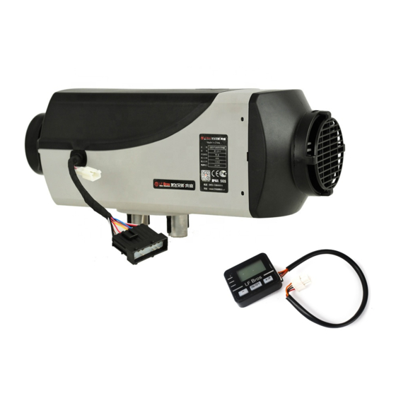
Packing list Packaged parts of the Air Heater: Name Specification Unit Quantity Main equipment 12V/24 V 2kW/3kW/5kW Main wire harness Fuel pump 12V/24 V (28 ml / 1000 times) Piece 1 Air outlet ø 60/90 mm Piece 1 LCD control switch Piece 1 Mechanical control switch Piece 1... -
Page 5: Overview
Overview The main equipment of air parking heater (hereinafter referred to as the heater) is a small fuel furnace controlled by a single-chip microprocessor. Its furnace body (that’s the heat exchanger) is located in the hood-shape case, which serves as an independent air passage. Cold air is sucked into the air passage by the heat supplying fan and blown out when it becomes hot... -
Page 6: Structure
Structure Fig. 2 Heater body Fig. 3 Case 1. heat exchanger 1. top hood cover 2. hood-shape case 2. bottom hood cover 3. controller board 3. hot air outlet 4. air inlet hood 3.1 Main heater body The main structure of the heater is described in Fig. 2. 3.2 Case The case structure is shown in Fig. -
Page 7: Temperature Sensor
3.3.2 Fault Lock The heater will automatically shut down and get into the locking state for protection when any the following conditions happen: 1. The heater can't be ignited or can't work naturally after being ignited. 2. Open or short circuit happens to the glow plug, fan motor, fuel pump and sensors, etc. 3. -
Page 8: Installation
3.5 Power Supply The heater shares the power supply with the car's engine but with a separate fuse. When the power supply voltage is outside of specified (lower and upper) limits the heater will automatically report the fault. 3.6 Fuel Supply The fuel used by the heater can be supplied by a special fuel tank. - Page 9 4.1 Requirements for Installation Requirements for installation and places of application of the heater: 1. It is not allowed to use the heater in locations with inflammable or explosive substances such as flammable gas or flammable dust. 2. It is not allowed to use the heater in closed space (such as garage or maintenance workshop without air ventilation) to avoid the danger of poisoning due to exhaust from burning.
- Page 10 4.2.3 Sealing Good sealing is necessary between the main equipment and the installation face on the vehicle. A special gasket (as shown in Fig. 6) supplied by the manufacturer must be padded for installation. The installation surface must be even enough. Its parts at the installation bases of the main equipment shall have unevenness less than 1 mm.
- Page 11 4.3 Installation of Air Heating System 4.3.1 Air circulation modes It's recommended to select the independent outer circulation or inner circulation mode of heater for installation. If the air heating system of the heater has to be connected with the air duct of the vehicle, in order to ensure the air duct unobstructed, the connection way should be decided by the professionals.
- Page 12 4.4 Installation of Fuel Supply System Fig. 11 Fuel supply system: Fig. 12 Elevation differences: 1 - Fuel tank 1 - Fuel pump 2 - Filter 2 - The highest level of fuel 3 - Fuel connecting pipe 3 - The lowest level of fuel 4 - Fuel pump 4 - Fuel inlet level for the main equipment ①...
-
Page 13: Control Panel
4.5 Installation of Electrical Components 4.5.1 Main wire harness Connection diagram of the main wire harness and the heater is as shown in Fig. 14. The wires of the main equipment for connection to outside circuits have been made into wire bundles. - Page 14 4.6 Installation of pipes Installation of Air inlet pile and Exhaust pipe. 4.6.1 Separate air circuits The combustion supporting air must be sucked in from the external fresh air outside the vehicle. The fumes from combustion must be discharged into the exterior air through the exhaust pipe.
- Page 15 4.6.5 High temperature When the heater is running the exhaust pipe is at high temperature. During installation make sure to install the pipe in the far distance from the plastic parts or other objects with the poor thermal resistance of the vehicle body. The exhaust pipe shall be properly fixed.
-
Page 16: Precautions
Precautions 5.1 Air in the fuel After installation of the heater, the air trapped in the fuel supply system shall be removed thoroughly to make the fuel line filled up with fuel. Please use the fuel pumping mode until the fuel lines are fully filled with the fuel. 5.2 Check before using The heater shall be commissioned before use. - Page 17 5.7 Life time The heat exchanger should not be used for more than 5 years. After expiration it must be replaced with genuine parts and replaced by the heater manufacturer or its authorized agent. At this time the overheating sensor shall also be replaced at the same time. If it's arranged in the area of passengers, the exhaust pipe of the heater for a discharge of fumes shall be replaced with genuine parts when the usage time is reaching 5 years.
-
Page 18: Usage
Usage 6.1 Modes of operation out of fuel refuelled shutdown fixed power mode fuel pumping cooling down starting up fixed temp. mode residual cleaning unclean shutdown 6.1.1 Fuel pumping (first start or after refueling) After the initial installation the heater should be started with the Fuel pumping mode to remove the air lock from the fuel pipes. - Page 19 Note: The maximum achievable temperature is dependent on the model of heater, volume of the heated cabin, exterior temperature and thermal resistance of the walls. 6.1.5 Shutdown After the shutdown is requested at the control panel the pump will stop immediately, but the fan will still run in order to cool down the heat exchanger case below 50 °C.
- Page 20 6.3.1 Fixed power mode Just setting a fixed power. Press the start button so that is in the released state. The start indicator light gets red. Turn the control knob to adjust the heater's power. It can be continuously adjusted between 1.4–MAX kW, where MAX is the maximum power of the model (3 or 5 kW).
- Page 21 6.4.2 Startup Fig. 24 Fig. 25 Fig. 26 Fig. 27 Long press the ON/OFF button for 3 seconds, the buzzer will beep, and the main display shows ON (Fig. 24). The glow plug will start to work in about 2 seconds. The display shows the current voltage in V, eg.
- Page 22 6.4.6 Start after unclean shutdown (ventilation mode) After the heater shut down in an unclean way it's necessary to blow away residual fuel left in the heater. After the residuals are cleaned one of the normal working modes should be selected. Long press the - button above 3 seconds.
-
Page 23: Troubleshooting
After adjusting wait 3 seconds for the buzzer to beep and the setting is completed. The display shows the set power, eg. P1.5 means 1.5 kW. Press the knob in this state to enter into the temperature mode adjustment. (Fig. 36). Fig. -
Page 24: Error Codes
After 5 seconds, the controller will turn off the heater, regarding it as a normal shutdown. In both cases make sure that all electrical connections are connected and then start as usual. Fig. 39 Fig. 40 Fig. 41 Fig. 42 7.2.2 Electric power failure The electric power may get suddenly disconnected and the heater will stop immediately. - Page 25 7.2.5 Table of error codes The following table describes the meaning of the error codes and possible causes: Error Code Fault Description Possible causes / solutions Control unit error / incorrect 1) replace the control panel parameter Failed to start (has been tried twice) 1) fuel exhaustion / failed to form a flame 2) bubbles in the oil line and the oil supply is...
- Page 26 overtemperature sensor is shorted Ignition needle is open 1) poor contact of the wire of ignition needle 2) ignition needle failure The overheat sensor is not 1) Pt1000 sensor is installed correctly positioned correctly Open circuit of setpoint generator 26/28...
-
Page 27: Maintenance Record
STANDARDS. 3. BEFORE THE USAGE, PLEASE INQUIRE QUALIFIED TECHNICIANS TO AVOID THE WRONG OPERATION. 4. PLEASE CONTACT LF BROS MAINTENANCE STATION. DO NOT DISASSEMBLY ARTIFICIALLY. It is necessary to inspect and maintain the heater by qualified installer before using every winter. - Page 28 All rights reserved Without the written permission of LF Bros NZ Pty Limited, any form of the pirate copy or reproduction of this manual is illegal. www.lfbros.co.nz Certifications 28/28...
Need help?
Do you have a question about the E Series and is the answer not in the manual?
Questions and answers
Getting an e 12 error code