
Related Manuals for Dish Network Pro Hybrid 42


Summary of Contents for Dish Network Pro Hybrid 42
-
Page 1: Installation Guide
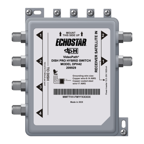
DISH Pro Hybrid 42 Switch Installation Guide VideoPath ® DISH PRO HYBRID SWITCH MODEL DPH42 209929 MMTTVV FMYYXXXXX Made in XXX... -
Page 2: Safety Information
Warning and Attention Symbols You must be aware of safety when you install and use the DISH Pro Hybrid 42 Switch. This document provides various procedures. If you perform some of these procedures carelessly, you could injure or kill yourself or damage equipment or property. - Page 3 Safety Information Guidelines Keep the following guidelines in mind when you install the DISH Pro Hybrid 42 Switch: • Before you drill any holes in the building or residence, ensure that there are no wires or pipes near the holes.
-
Page 4: Table Of Contents
Table of Contents Safety Information ..................2 Introduction ....................5 Installation Instructions ................6 Wiring Diagrams ..................8 Cable-Runs for Channel-Stack Splitters .......... 11 Limited Warranty ..................12 FCC Compliance ..................13 Copyright Notice ..................14 DPH42 Installation Guide... -
Page 5: Introduction
Introduction This guide explains how to install the DISH Pro Hybrid 42 Switch (DPH42 Switch), which connects up to four satellite feeds from a DISH Pro (DP) or DISH Pro Plus (DPP) LNBF to Hopper , Joey , Wally , ViP , and ®... -
Page 6: Installation Instructions
Installation Instructions Connecting the Switch Ensure that the dish is receiving the strongest-possible signal. Mount the DPH42 Switch onto a sturdy structure, such as the side of a building. Make sure that the mounting location is stable and that you fasten the switch tightly to the surface using suitable hardware for the mounting surface. - Page 7 Installation Instructions Ground the system in accordance with the National Electrical Code (NEC) and all state and local ® electrical codes. Note: The DPH42 Switch is UL-listed as an approved grounding block. Connect RG-6 cables from the LNBF(s) to the T ports on the DPH42 Switch.
-
Page 8: Wiring Diagrams
Wiring Diagrams The diagrams on the following pages represent possible wiring configurations using the DPH42 Switch. Note that grounding and Internet connectivity have been removed for clarity. The wiring diagrams in this section omit cable drip/service loops and grounding. Use drip/service loops and ground the system in accordance with NEC , state, and local electrical codes. - Page 9 Wiring Diagrams Mixed Receiver System This diagram shows how to connect the DPH42 Switch in an installation that features different supported receivers. Note: For multiple-Wally installations, the DPH42 Power Inserter must be installed between the switch and a splitter, as shown below. Also, cable-runs cannot exceed 140 feet between the farthest LNBF and the farthest receiver. See the table on page 11 for more details.
- Page 10 Wiring Diagrams Multiple Dwelling Unit This diagram shows how to connect the DPH42 Switch in an MDU installation. Note: For multiple-Wally installations, the DPH42 Power Inserter must be installed between the switch and a splitter, as shown below. Also, cable-runs cannot exceed 140 feet between the farthest LNBF and the farthest receiver. See the table on page 11 for more details.
-
Page 11: Cable-Runs For Channel-Stack Splitters
Cable-Runs for Channel-Stack Splitters Number of Receivers 2-Way Splitters 4-Way Splitters Maximum Cable Length 200 ft. 200 ft. 200 ft. 185 ft. 185 ft. 185 ft. 185 ft. 140 ft. 140 ft. 140 ft. 140 ft. 140 ft. 140 ft. 140 ft. -
Page 12: Limited Warranty
This warranty does not cover installation of the DISH Network system; consumer instruction; physical set up or adjustment of any consumer electronic device; signal reception problems; loss of use of the equipment; unused programming charges due to equipment malfunction;... -
Page 13: Fcc Compliance
FCC Compliance This device complies with Part 15 of FCC Rules. Operation is subject to the following two conditions: This device may not cause harmful interference; This device must accept any interference received, including interference that may cause undesired operation. This equipment has been tested and found to comply with the limits for a Class B digital device, pursuant to Part 15 of the FCC Rules. -
Page 14: Copyright Notice
Copyright Notice © 2017 EchoStar Technologies L.L.C., Englewood, Colorado 80112. All rights reserved. DISH is a registered trademark of DISH Network L.L.C. All product names, trade names, or corporate names mentioned in this document are acknowledged to be the proprietary property of the registered owners.
Need help?
Do you have a question about the Pro Hybrid 42 and is the answer not in the manual?
Questions and answers