
Subscribe to Our Youtube Channel
Summary of Contents for Elma T310H
- Page 1 Service Manual Transsonic Analog Transsonic LC Ultrasonic Cleaning Units english Elma GmbH & Co KG Kolpingstr. 1-7 D-78224 Singen Tel. +49(0)7731/882-0 Fax +49(0)7731-266 info@elma-ultrasonic.com www.elma-ultrasonic.com...
-
Page 3: Table Of Contents
How to replace the overheating protection on T310/H33 How to remove the overheating protection on LC 20H – LC 130H................35 How to replace the front plate ........38 How to replace the heating........40 9.1.1 Wiring 230V............44 9.1.2 Wiring 230V............45 SM/TRANSSONIC_LC/1004/D © Elma GmbH & Co KG... - Page 4 Putting out of operation and disposal ....106 Manufacturer contact address ......106 Conclusion............106 Annex ..............107 21.1 Annex A – Circuit diagrams ........107 21.2 Annex B – Spare parts lists ........107 SM/Transsonic_LC/1104/D © Elma GmbH & Co KG...
-
Page 5: General
2, Important operation instructions and section 17, Putting into operation / Trial runs. In case of any further queries ELMA will be glad to assist. For our technical support and contact address please see the last page. -
Page 6: Demands On The Service Staff
The manufacturer cannot be held liable for damages on Exclusion of liability persons, unit or shop equipment caused by improper use of the unit or wrong repair works. SM/Transsonic_LC/1104/D © Elma GmbH & Co KG... -
Page 7: Testing Equipment, Tools And Measuring Instruments
Double-beam oscilloscope with minimum 20 MHz elementary frequency. Two probes 1:1 and/or 1:10. Probes For the connection between mains and oscilloscope. Interrupting Required for the galvanic separation of the oscilloscope from transformer the mains. Nominal power approx. 50VA. © Elma GmbH & Co KG SM/Transsonic_LC/1104/D... -
Page 8: Important Operating Instructions
Important operating instructions Carefully read and observe before reoperation and inspection of the unit! The present Elma ultrasonic cleaning unit has been designed Intended use for the treatment of items and liquids only. Check the unit and the mains cable for transport damages. In... -
Page 9: Organizational Details
New units date of purchase). If no proof of purchase can be produced, Elma can find out the date of manufacturing by means of the serial number (nameplate). Elma grants a limitation period of 2 years on all exchange parts Repair and on any repair works carried out. -
Page 10: Description Of Operating Elements
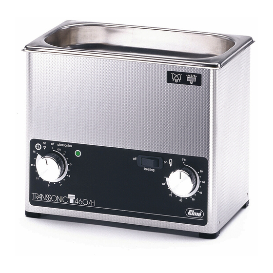
Operating modes: 1 - 15 min for short-period operation permanent operation ∞ (manual switch-off required). Heating switch On / Off switch for heating. Pilot lamp ultrasound Turns on when ultrasound is activated. Thermostat Stepless regulation of the heating temperature. SM/Transsonic_LC/1104/D © Elma GmbH & Co KG... -
Page 11: Technical Details
TP690 TP690H TP695H 5.8 / 7.4 T700 T700H T780 T780H T820H 1050 10.2 T890 12.2 T890H 1100 12.7 T1040H 2000 1600 24.6 T1060H 2800 2000 38.5 LC20H LC 30 LC 30H LC60H LC130H © Elma GmbH & Co KG SM/Transsonic_LC/1104/D... -
Page 12: Trouble Shooting / List Of Malfunctions
An insufficient heating temperature or incorrect temperature regulation are generally caused by an unsuitable heating process. Please find further information in sections 8.5 and 9. SM/Transsonic_LC/1104/D © Elma GmbH & Co KG... -
Page 13: T310(H)
• replace faulty heating • • No ultrasound interference filter replace complete printed board • mains cable No heating • replace mains cable © Elma GmbH & Co KG SM/Transsonic_LC/1104/D... - Page 14 No ultrasound • replace faulty heating • faulty heating switch • replace component No heating (Ultrasound OK) • • No heating faulty thermostat replace component button (check with ohmmeter) (Ultrasound OK) SM/Transsonic_LC/1104/D © Elma GmbH & Co KG...
-
Page 15: T420(H); Lc20H
(Heating OK) • mains cable filter • replace mains cable No heating; • • scorched replace interference complete printed filter board No ultrasound • • faulty mains replace mains cable cable © Elma GmbH & Co KG SM/Transsonic_LC/1104/D... - Page 16 No ultrasound heating is faulty: • replace faulty heating • • No heating faulty heating replace switch component (Ultrasound OK) • • No heating faulty replace thermostat (no component „click“) (Ultrasound OK) SM/Transsonic_LC/1104/D © Elma GmbH & Co KG...
-
Page 17: T460 - T 700H; Lc 30 - Lc 130H
(Heating OK) • timer filter • replace timer • • No ultrasound interference replace filter compl. Inter- No heating • mains cable ference filter • replace mains cable • replace component © Elma GmbH & Co KG SM/Transsonic_LC/1104/D... - Page 18 Fuse ilter (e.g. automatic liquid) (building) released • • No heating faulty replace heating component switch Ultrasound (perm. interrupted) • • No heating faulty replace thermostat component (no „click“; Ultrasound perm. interrupted) SM/Transsonic_LC/1104/D © Elma GmbH & Co KG...
-
Page 19: T780 - T1060H
(Heating OK) • • timer replace compl. interf. filter • • No ultrasound interference replace filter component No heating • • mains cable replace compl. interf. filter • replace mains cable © Elma GmbH & Co KG SM/Transsonic_LC/1104/D... - Page 20 (e.g. Fuse liquid) automatic in building released • • No heating faulty replace heating component switch Ultrasound (perm. interrupted) • • No heating faulty replace thermostat component (no „click“; Ultrasound perm. interrupted) SM/Transsonic_LC/1104/D © Elma GmbH & Co KG...
-
Page 21: Block Diagram T310 - T420H; Lc20H - Lc30H
Trouble shooting / List of malfunctions Block diagram T310 – T420H; LC20H – LC30H Datei:c:\daten\texte\techdok\...\BLOCK01.DRW © Elma GmbH & Co KG SM/Transsonic_LC/1104/D... -
Page 22: Block Diagram T460 - T700H; Lc60H - Lc130H
Trouble shooting / List of malfunctions Block diagram T460 – T700H; LC60H – LC130H Datei:c:\daten\texte\techdok\...\BLOCK02.DRW SM/Transsonic_LC/1104/D © Elma GmbH & Co KG... -
Page 23: Block Diagram T780 - T1060H
Trouble shooting / List of malfunctions Block diagram T780 – T1060H Datei:c:\daten\texte\techdok\...\BLOCK03.DRW © Elma GmbH & Co KG SM/Transsonic_LC/1104/D... -
Page 24: How To Open The Unit
2. Pull off the timer turning knob. 3. Remove the recessed head screw (Illustration 7.1.1.) Illustration 7.1.1. Remove the recessed head screw (under the turning knob) Illustration 7.1.2. Timer angle with thread (A) for recessed head screw SM/Transsonic_LC/1104/D © Elma GmbH & Co KG... - Page 25 Use a screw driver to press the support angle against the housing in order to prevent the angle from receding. For this insert the screw driver between bottom plate and housing. © Elma GmbH & Co KG SM/Transsonic_LC/1104/D...
-
Page 26: Faulty Operating And Switch Elements
Caution: Do not press the timer turning knob excessively as this might damage the thread in the support angle. Illustration 8.1.1. Coding of shaft for timer turning knob SM/Transsonic_LC/1104/D © Elma GmbH & Co KG... -
Page 27: How To Replace The Timer
1 and 2. 8. Mount the turning knob as described in section 8.1. 9. Mount the bottom plate; close the unit. Make sure that all plug connections are correct and that no cables are pinched. © Elma GmbH & Co KG SM/Transsonic_LC/1104/D... - Page 28 Generator Datei:c.\daten\texte\techdok\...\BILD003.DRW Bild 3 Haltewinkel Zeitschaltuhr Illustration 8.2.2. top: timer type DIEHL in units made before 1997 bottom: timer type COUPATAN in units made since 1997, this timer is delivered as spare part SM/Transsonic_LC/1104/D © Elma GmbH & Co KG...
-
Page 29: How To Replace The Heating Switch
The unit had been equipped with a lighed heating switch: Connect the two electric cables which had been plugged to contact 1 and 2 with the two available plug contacts. Polarization of the cables is irrelevant. © Elma GmbH & Co KG SM/Transsonic_LC/1104/D... - Page 30 Without opening of the unit: Variant B Lever the heating switch out of the plate from the front; use a suitable tool, e.g. screw driver, knife. Then follow the steps 2, 4 and 5. SM/Transsonic_LC/1104/D © Elma GmbH & Co KG...
- Page 31 Use a suitable narrow tool to lever the switch out from the side Carefully pull the switch out of the housing. Ensure that the cables do not come lose and remain inside the unit. Secure the cables against sliding back Illustration 8.3.4. Secure the cables © Elma GmbH & Co KG SM/Transsonic_LC/1104/D...
-
Page 32: How To Replace The Control Thermostat T420H-T1060H
6. Loosen the two fastening screws (Illustration 8.7.3.A) at the front plate and remove the control thermostat. 7. Pull out the temperature probe which is fixed to the metal clamp on the tank outside. If required, cut the silicon (Illustration 8.7.2.). SM/Transsonic_LC/1104/D © Elma GmbH & Co KG... - Page 33 8.7.1.), polarization is irrelevant. Before closing the housing check again that no cable has come loose or is pinched. Illustration 8.7.1. Electric connections at control thermostat Supply cable from heating switch Cable to heating © Elma GmbH & Co KG SM/Transsonic_LC/1104/D...
- Page 34 Illustration 8.7.2. Clamped-in capillary probe secured with silicone red dotted line: cut silicone here to remove the probe Illustration 8.7.3. Pull off the foil around the control thermostat Fastening screws for control thermostat SM/Transsonic_LC/1104/D © Elma GmbH & Co KG...
-
Page 35: How To Replace The Overheating Protection On
5. Connect the electric contacts. Polarization is irrelevant. 6. After the silicone has hardened check if all connections are correct and close the unit. Illustration 8.5.1 Position and silicone fixation of overheating © Elma GmbH & Co KG SM/Transsonic_LC/1104/D... - Page 36 Illustration 8.5.2. Wiring of heating switch, here lighted model. For the unlighted heating switch connection 3 is irrelevant. SM/Transsonic_LC/1104/D © Elma GmbH & Co KG...
-
Page 37: How To Remove The Overheating Protection On Lc 20H - Lc 130H
7. Connect the electric cables and insulate the connections. Polarization is irrelevant. 8. Reinsert the tank as described in section 11. 9. Connect all remaining electric cables. 10. Close the unit. © Elma GmbH & Co KG SM/Transsonic_LC/1104/D... - Page 38 Illustration 8.6.1. Overheating protection (since Feb 2002) mounted and connected Position of probe in models since Feb. 2002 Illustration 8.6.2. Capillary probe clamped-in and secured with silicone (since Feb 2002) red dotted line: cut silicone here to remove the probe SM/Transsonic_LC/1104/D © Elma GmbH & Co KG...
- Page 39 Faulty operating and switch elements interference filter heating Illustration 8.6.3. Wiring of heating switch, here lighted model. For the unlighted heating switch connection 3 is irrelevant. © Elma GmbH & Co KG SM/Transsonic_LC/1104/D...
-
Page 40: How To Replace The Front Plate
7. Mount all remaining switch elements (see also section 8.1.). Carefully screw in the screw, do not damage the thread in the timer angle. Pull off the turning knobs and loosen the screw Illustration 8.7.1. Unit with turning knobs pulled off SM/Transsonic_LC/1104/D © Elma GmbH & Co KG... - Page 41 Faulty operating and switch elements Lever out the heating switch Illustration 8.7.2. Levering the heating switch out of the housing Pull off the foil Illustration 8.7.3. Secure the electric cables, carefully remove the foil. © Elma GmbH & Co KG SM/Transsonic_LC/1104/D...
-
Page 42: How To Replace The Heating
(see Illustration 9.1.). Caution: Do not use any sharp tools to scratch off the deposits. Lime deposits around the heating element Illustration 9.1. Lime deposits due to insufficient stirring SM/Transsonic_LC/1104/D © Elma GmbH & Co KG... - Page 43 230 V 200 000 7157 / 115 V 200 000 7216 Elma Order No. In most units, the heating element can be replaced without removal of the tank. Exceptions are the units T310H, T420H, T780H, T820H: In these units the transducer tank must be removed as described in section 11.
- Page 44 Push the heating element(s) out of the guiding rails in the marked direction. Push the heating element downward out of the guiding rails. Put the new heating element into the guiding rails from above. Carefully push it down into the guiding rails without jamming. SM/Transsonic_LC/1104/D © Elma GmbH & Co KG...
- Page 45 Put the new heating element into the guiding rails in the marked direction (B). Carefully push it into the guiding rails without jamming. Then secure against displacement with silicone. © Elma GmbH & Co KG SM/Transsonic_LC/1104/D...
-
Page 46: Wiring 230V
2 heating elements are wired in a line. The third element is 3 Heating elements connected parallel to the two other elements. 2 elements each are wired in a line and connected parallel with 4 and more heating the other element pairs. elements SM/Transsonic_LC/1104/D © Elma GmbH & Co KG... -
Page 47: Wiring 230V
2 heating elements are wired in a line. The third element is 3 Heating elements connected parallel to the two other elements. 2 elements each are wired in a line and connected parallel with 4 and more heating the other element pairs. elements © Elma GmbH & Co KG SM/Transsonic_LC/1104/D... -
Page 48: Faulty Pxe Transducer Disks
Therefore, all transducer disks should be replaced even if only individual PXE transducer disks are faulty. Elma deliver preselected sets of transducer disks. PXE transducer disks can be damaged for different reasons Cause of breakdown (mostly tears): e.g. - Page 49 The torque wrench must be held vertically to the transducer system during the complete process of unscrewing. The power given to the handle of the tool must be exactly countered by the hand that centers the tool (see Illustration 10.1.). © Elma GmbH & Co KG SM/Transsonic_LC/1104/D...
- Page 50 Branch off the electric charge by short circuiting between two terminal lugs, e.g. with a screw driver. Illustration 10.1.1. Always hold the torque wrench vertically. Do not tilt the tool! SM/Transsonic_LC/1104/D © Elma GmbH & Co KG...
- Page 51 1 PXE disk (E 35) Illustration 10.1.2. Transducer system with 1 PXE transducer disk Structure of transducer system with 2 PXE disks (W 35) Illustration 10.1.3. Transducer system with 2 PXE transducer disks 35 © Elma GmbH & Co KG SM/Transsonic_LC/1104/D...
- Page 52 Illustration 10.1.4. Transducer system with 2 PXE transducer disks 40 Pressure piece (shape depending on frequency of the system) Terminal lug MINUS connection PXE transducer disk Terminal lug PLUS connection Aluminum washer Aluminum coupling piece SM/Transsonic_LC/1104/D © Elma GmbH & Co KG...
- Page 53 PXE transducer disk "+" Terminal lug PXE transducer disk aluminum washer coupling piece Fig 7 Illustration 10.1.5. left: structure of 2-disk transducer system right: structure of 1-disk transducer system © Elma GmbH & Co KG SM/Transsonic_LC/1104/D...
-
Page 54: How To Replace The Transducer Tank
Cavitational erosion Illustration 11.1. Heavy cavitational erosion at the spot where the transducer system is fixed Illustration 11.2. Leaking tank floor with traces of liquid SM/Transsonic_LC/1104/D © Elma GmbH & Co KG... - Page 55 (see Illustration 11.1.1). 7. Carefully lever the tank out of the housing (see Illustration 11.1.2). 8. Remove the silicone remains on the tank and the edge of the housing with a knife. © Elma GmbH & Co KG SM/Transsonic_LC/1104/D...
- Page 56 Seal the thread e.g. with Loctite 586 or Teflon tape (see also section 12). 14. Reconnect all electric cables. Heat up silicone sealing and cut Illustration 11.1.1. Heat up the silicone sealing in the tank edge and cut with a knife. SM/Transsonic_LC/1104/D © Elma GmbH & Co KG...
- Page 57 How to replace the transducer tank Lever the housing from the tank Illustration 11.1.2. Carefully lever the housing from the tank at different spots © Elma GmbH & Co KG SM/Transsonic_LC/1104/D...
-
Page 58: How To Replace The Ball Valve
If this is a problem, loosen the lock nut again and adjust the ball valve accordingly. SM/Transsonic_LC/1104/D © Elma GmbH & Co KG... - Page 59 Illustration 12.1.2. 3/8“ drain duct: Open the ball valve with a 19 mm fork wrench anti-clockwise Illustration 12.1.3. 3/8“ drain duct: Secure the duct nipple (A) with a pipe wrench to avoid an opening of the sealing in the duct angle (B). © Elma GmbH & Co KG SM/Transsonic_LC/1104/D...
- Page 60 Illustration 12.1.5. Heat the Loctite thread sealing with a hot air fan Illustration 12.1.6. Secure the duct nipple (A) with a pipe wrench to avoid an opening of the sealing in the duct angle (B). SM/Transsonic_LC/1104/D © Elma GmbH & Co KG...
-
Page 61: How To Replace The Interference Filter
Supply cable interference filter >> timer input. Polarization irrelevant. On units with heating the cable for the heating is connected to the twin contacts. Supply cable timer output >> generator. Polarization irrelevant. Mains supply phase (brown). © Elma GmbH & Co KG SM/Transsonic_LC/1104/D... -
Page 62: Interference Filter On T460 - T700H
Polarization irrelevant. On units with heating the cable for the heating is connected to the twin contacts. Supply cables timer output >> generator. Polarization irrelevant. Mains supply phase (brown). Earthing contacts. Mains supply zero (blue). Mains supply heating. Interference filter coil. SM/Transsonic_LC/1104/D © Elma GmbH & Co KG... -
Page 63: Interference Filter On T780 - T1040/H
Interference filter on old units Illustration 13.3.1. Interference filter on units made before 2002 Interference filter on new units Illusration 13.3.2. Interference filter on units made since 2002 © Elma GmbH & Co KG SM/Transsonic_LC/1104/D... - Page 64 On units as shown in Illustration 13.3.2. connection K2. Mains supply zero (blue). On units as shown in Illustration 13.3.2. connection K1. The lower contact is insulated because of its closeness to the bottom plate. Interference filter coil. SM/Transsonic_LC/1104/D © Elma GmbH & Co KG...
-
Page 65: How To Replace The Ultrasonic Generator
Check if all cables are connected correctly. • If the fuse on the generator print is blown there usually is a short circuit in the semiconductors and/or there is a short circuit caused by humidity inside. © Elma GmbH & Co KG SM/Transsonic_LC/1104/D... - Page 66 5. Adjustment of the generator as described in section 16.ff. Wrong adjustment can destroy the generator and the transducer disks. 6. Reconnect all other cables. Caution! Observe correct polarization. 7. Reassemble the unit and ensure that all cables are connected correctly. SM/Transsonic_LC/1104/D © Elma GmbH & Co KG...
-
Page 67: T310 - T420H; Lc20H - Lc30H
Illustration 14.1.1. Generator print mounted onto bottom plate (front view) Supply cable to heating (on units with heating); polarization irrelevant Plug contact 6.3 mm: HF output (-) to transducer system Plug contact 4.8 mm: HF output (+) to transducer system © Elma GmbH & Co KG SM/Transsonic_LC/1104/D... - Page 68 Illustration 14.1.2 Generator print mounted onto bottom plate (back view) Supply cables generator >> timer input. Polarization irrelevant. Supply cables timer output >> generator. Polarization irrelevant. Mains supply phase (brown). Earthing cables. Mains supply zero (blue). SM/Transsonic_LC/1104/D © Elma GmbH & Co KG...
-
Page 69: T460 - T470H; Lc60H
6. Reconnect all other cables. Caution! Observe correct polarization. 7. Reassemble the unit and ensure that all cables are connected correctly. 8. Trial operation approx. 2 – 3 h. © Elma GmbH & Co KG SM/Transsonic_LC/1104/D... - Page 70 Plug contact 4.8 mm: HF output (+) to transducer system. Plug contact 6.3 mm: HF output (-) to transducer system. Earthing connection generator print >> earthing point bottom plate (units made since 2000). Holding clamps for transistors. Insulating sleeves for transistors. SM/Transsonic_LC/1104/D © Elma GmbH & Co KG...
-
Page 71: Ts540 - T700H; Lc130H
6. Reconnect all other cables. Caution! Observe correct polarization. 7. Reassemble the unit and ensure that all cables are connected correctly. 8. Trial operation approx. 2 – 3 h. © Elma GmbH & Co KG SM/Transsonic_LC/1104/D... - Page 72 Plug contact 4.8 mm: HF output (+) to transducer system. Plug contact 6.3 mm: HF output (-) to transducer system. Earthing connection generator print >> earthing point bottom plate (units made since 2000). Holding clamps for transistors. Insulating sleeves for transistors. SM/Transsonic_LC/1104/D © Elma GmbH & Co KG...
-
Page 73: T780 - T1060H
6. Reconnect all other cables. Caution! Observe correct polarization. 7. Reassemble the unit and ensure that all cables are connected correctly. 8. Trial operation approx. 2 – 3 h. © Elma GmbH & Co KG SM/Transsonic_LC/1104/D... - Page 74 Illustration 14.4.2. Detailed view HF output HF (+) output (plug ocntact 6.3 mm). Earthing point (plug contacts 6.3 mm). Mass connection (-) generator >> earthing point (D). HF (+) output >> supply transducer system. SM/Transsonic_LC/1104/D © Elma GmbH & Co KG...
- Page 75 How to replace the ultrasonic generator Additional capacitor T1040H T1060H Illustration 14.4.2. Additional capacitor HF output >> supply additional capacitor. Output additional capacitor (bridged with G). HF (+) output >> supply transducer system (bridged with F). Additonal capacitor. © Elma GmbH & Co KG SM/Transsonic_LC/1104/D...
-
Page 76: How To Replace Components On The Generator Print
18 kOhm / 1W can be faulty due to a short circuit of the transistors. Check with ohmmeter. 1,2 Ohm / 4W: 200 000 5004 Elma Order No. 100 Ohm / 0,5W: 200 000 5005 18 kOhm / 1W: 200 000 5033 SM/Transsonic_LC/1104/D © Elma GmbH & Co KG... - Page 77 16.4.). The graph remains flat (see section 16.2.4.). T310 115V/230V; LC20H 230V : 200 000 1458 Elma Order No. LC 20H 115V: 200 000 1564 Illustration 15.1.1. Generator print with relevant components Transistors BZW diode Output transformer Output capacitor © Elma GmbH & Co KG SM/Transsonic_LC/1104/D...
-
Page 78: T460 - T470H; Lc60H
The transistors are preselected by Elma. Spare part deliveries always contain transistors with equal amplification factor. If the fuse on the generator print is blown check the transducers. - Page 79 16.4.). The graph remains flat (see section 16.2. Illustration 16.2.4.). 115V: 200 000 1460 / 230V: 200 000 1459 Elma Order No. Illustration 15.2.1 Generator print with relevant components Transistors Mains rectifyer diodes 1N4007 (4 pieces) Varistor Output transformer Output capacitors © Elma GmbH & Co KG SM/Transsonic_LC/1104/D...
-
Page 80: Ts540 - T700H; Lc130H
The transistors are preselected by Elma. Spare part deliveries always contain transistors with equal amplification factor. If the fuse on the generator print is blown check the transducers. - Page 81 9. Secure the coil with silicone. Ensure that all cables are free so that no short circuit can occur. Secondary coil 115V 200 000 7211 Elma Order No. Secondary coil 230V 200 000 7205 © Elma GmbH & Co KG SM/Transsonic_LC/1104/D...
- Page 82 How to replace components on the generator print Illustration 15.3.1 Generator print with relevant components Transistors Mains rectifyer diodes 1N4007 (4 pieces) Varistor Output transformer (secondary coil) Output capacitors SM/Transsonic_LC/1104/D © Elma GmbH & Co KG...
-
Page 83: T780 - T1060H
The transistors are preselected by Elma. Spare part deliveries always contain transistors with equal amplification factor. If the fuse on the generator print is blown check the transducers.. - Page 84 The diodes (BA 159 or DSEI8-06A on T1040-T1060 115V) can Diodes be faulty in case of a short circuit of the transistors. BA 159: 200 000 6123 Elma Order No. DSEI8-06A: 200 000 5149 SM/Transsonic_LC/1104/D © Elma GmbH & Co KG...
- Page 85 Ensure that all cables are free so that no short circuit can occur. Secondary coil (120 wraps) T780; T820H: 200 000 7096 Elma Order No. Secondary coil (110 wraps) T890: 200 000 7133 © Elma GmbH & Co KG SM/Transsonic_LC/1104/D...
- Page 86 Secondary coil (102 wraps) T1040H; T1060H: 200 000 7112 Illustration 15.4.3. Generator print with relevant components Transistors HF diodes (BA 159 or DSEI8-06A on T1040-T1060 115V ) Varistor Output transformer (secondary coil) Output capacitor (4 pieces) SM/Transsonic_LC/1104/D © Elma GmbH & Co KG...
-
Page 87: Adjustment Of The Generators
The generator print must be operated with connected NOTE transducer system only. Risk of damage to the electronics by thermic overload Operate the generator only with the transistors fixed to the NOTE relevant cooling body (bottom plate etc.) © Elma GmbH & Co KG SM/Transsonic_LC/1104/D... -
Page 88: Set-Up Of Measuring Instruments
(See also section 17. Initial operation and 17.2. Cleaning media) Connect the transducer system to the output of the generator Connect the print before putting any voltage on the set-up. transducer system SM/Transsonic_LC/1104/D © Elma GmbH & Co KG... - Page 89 The ultrasonic effect is unsatisfactory: there are no waves on the surface of the bath, there are streamers on the tank floor, there is an unusual noise, the transistors heat up, etc. © Elma GmbH & Co KG SM/Transsonic_LC/1104/D...
- Page 90 Caution: The screw driver will heat up considerably due to induction! Illustration 16.2.4.: Current graph in case of short circuit in output transformer or transducer system SM/Transsonic_LC/1104/D © Elma GmbH & Co KG...
-
Page 91: Table Of Power Consumption Values Ultrasound
225 - 275 T820/H 225 - 275 T890(/H) 250 - 300 T1040/H 400 - 450 T1060/H 800 - 900 LC20/H 30 - 40 LC30(/H) 30 - 40 LC60/H 70 - 85 LC130/H 140 - 150 © Elma GmbH & Co KG SM/Transsonic_LC/1104/D... -
Page 92: Adjustment On T310 - T420H; Lc20H - Lc30H
Illustration 16.2.1. 5. Check the generator power consumption and compare with the values indicated in the table in section 16.3. In case of deviation see instructions given in section 16.2. SM/Transsonic_LC/1104/D © Elma GmbH & Co KG... - Page 93 If output too high (compare Table 15.3.) slightly turn out ferrite core anti-clockwise. If output too low (compare Table 15.3.) slightly turn in ferrite core clockwise. Caution: The tip of the screw driver can heat up considerably by induction. © Elma GmbH & Co KG SM/Transsonic_LC/1104/D...
- Page 94 Adjustment of the generators Cable for adjustment Illustration 16.4.2. Unsolder the cable of control coil for adjustment and add or reduce number of wraps at the coil. SM/Transsonic_LC/1104/D © Elma GmbH & Co KG...
- Page 95 Output transformer Ausgangs- übertrager Entstör- drossel Zuleitung to transducer Schwinger Generatorplatine T310(/H), T420, LC20/H, LC30(/H) ab Januar 1992 Bild 9 Illustration 16.4.3. top: units made before February 1992 bottom: units made since February 1992 © Elma GmbH & Co KG SM/Transsonic_LC/1104/D...
-
Page 96: Adjustment On T460 - T470H; Lc60H
There are no streamers on the tank floor. • The ultrasonic noise is uniform and not shrill. • The performance changes only little when a beaker, etc. is immersed in the tank. The phases remain stable. SM/Transsonic_LC/1104/D © Elma GmbH & Co KG... - Page 97 If output too low (compare Table 14.3) slightly turn ferrite core in clockwise. Caution: The tip of the screw driver can heat up considerably due to induction. Illustration 16.5.2. Generator print: relevant adjustment points © Elma GmbH & Co KG SM/Transsonic_LC/1104/D...
- Page 98 Uhr Tuning coil MP2(CH2) MP1(CH1) up from 1997 Bild 10 T460(/H), T470/H, LC60/H ab Februar 1992 Datei:c:\daten\texte\techdok\...\BILD010.DRW Illustration 16.5.3. top: units before February 1992 bottom: units since February 1992 SM/Transsonic_LC/1104/D © Elma GmbH & Co KG...
-
Page 99: Adjustment On Ts540 - T700H; Lc130H
There are no streamers on the tank floor. • The ultrasonic noise is uniform and not shrill. • The performance changes only little when a beaker, etc. is immersed in the tank. The phases remain stable. © Elma GmbH & Co KG SM/Transsonic_LC/1104/D... - Page 100 R6 – on transistor side MP2). Mass connection of probe channel 2 (resistance R6 – Gnd). Adjustment coil to carry out adjustment: turn ferrite core in or out (according to instructions). SM/Transsonic_LC/1104/D © Elma GmbH & Co KG...
- Page 101 Tuning coil zur Uhr spule MP2(CH2) MP1(CH1) Bild 11 TS540, T570(/H), T660/H, TP690, Datei:c:\daten\texte\techdok\...\BILD011.DRW T700(/H), LC130/H ab 1992 Illustration 16.6.2. top: units made before February 1992 bottom: units made since February 1992 © Elma GmbH & Co KG SM/Transsonic_LC/1104/D...
-
Page 102: Adjustment On T780 - T1060H
There are no streamers on the tank floor. • The ultrasonic noise is uniform and not shrill. • The performance changes only little when a beaker, etc. is immersed in the tank. The phases remain stable. SM/Transsonic_LC/1104/D © Elma GmbH & Co KG... - Page 103 (according to instructions). Illustration 16.7.2. Adjustment coil, latest model. Older units can be equipped with adjustment coils of the former model. The model of the coil has no influence on the functioning of the unit. © Elma GmbH & Co KG SM/Transsonic_LC/1104/D...
- Page 104 Tuning coil Abstimm- transducer hwinger spule only 40kHz models nur bei 40 kHz T1040 H / T1060H 1040 / T1060 Bild 12 Datei:c:\daten\texte\techdok\...\BILD012.DRW Illustration 16.7.3. Model with and without additional capacitors. SM/Transsonic_LC/1104/D © Elma GmbH & Co KG...
-
Page 105: Putting Into Operation / Trial Run
How to degas the cleaning effect of the ultrasonic activity. Sounding the liquid liquid over a period of several minutes before the actual cleaning process is started will eliminate the microscopic air bubbles from the liquid. © Elma GmbH & Co KG SM/Transsonic_LC/1104/D... -
Page 106: Cleaning Media
(minimum). The optimum filling level is marked on the at thermostat tank wall. In order to achieve an even heating of the cleaning liquid switch on the ultrasound from time to time or stir the liquid by hand. SM/Transsonic_LC/1104/D © Elma GmbH & Co KG... -
Page 107: Check Ultrasound
The size of the torn holes indicates the zones of different cleaning intensity in the cleaning tank. It is normal that the number of holes is bigger around the transducer elements. © Elma GmbH & Co KG SM/Transsonic_LC/1104/D... -
Page 108: Putting Out Of Operation And Disposal
The components can be given to electronic and metal recycling stations or returned to the manufacturer for the same purpose. Manufacturer contact address Elma Hans Schmidbauer GmbH & Co. KG Kolpingstr. 1-7, D-78224 Singen Phone:++49 (0) 7731 882-0 Fax:++49 (0) 7731 882-266 E-mail: info@elma-ultrasonic.com... -
Page 109: Annex
Annex B – Spare parts lists Please contact the manufacturer for any spare parts list you may require. Spare parts can be ordered from Elma or from your supplier. Please make sure to indicate the type of unit and the serial number (nameplate).
Need help?
Do you have a question about the T310H and is the answer not in the manual?
Questions and answers