Sign In
Upload
Download
Table of Contents
Contents
Add to my manuals
Delete from my manuals
Share
URL of this page:
HTML Link:
Bookmark this page
Add
Manual will be automatically added to "My Manuals"
Print this page
×
Bookmark added
×
Added to my manuals
Manuals
Brands
JDiag Manuals
Barcode Reader
FasDiag JD301
User manual
JDiag FasDiag JD301 User Manual
Hide thumbs
1
2
3
4
5
6
7
8
9
10
11
12
13
14
15
16
17
18
19
20
21
22
23
24
Table Of Contents
25
page
of
25
Go
/
25
Contents
Table of Contents
Bookmarks
Table of Contents
General Information
On-Board Diagnostics (OBD)
OBD II Readiness Monitors
Using the Scan Tool
Specifications
Accessories Included
System Setup
To Enter the Setup Menu
Language Setup
Configure Monitors
Key Beep Set
Keyboard Test
OBDII Diagnostics
Reading Codes
Erasing Codes
Retrieving I/M Readiness Status
Viewing Vehicle Information
Advertisement
Quick Links
1
General Information
2
On-Board Diagnostics (Obd)
3
Using the Scan Tool
4
System Setup
5
Obdii Diagnostics
6
Reading Codes
7
Viewing Vehicle Information
Download this manual
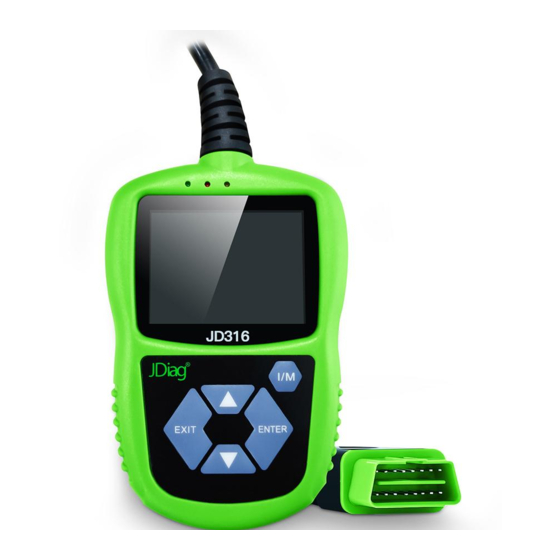
FasDiag JD301/316
User Manual
OBDII Car Diagnostic Scanner
Table of
Contents
Previous
Page
Next
Page
1
2
3
4
5
Advertisement
Table of Contents
Need help?
Do you have a question about the FasDiag JD301 and is the answer not in the manual?
Ask a question
Questions and answers
Related Manuals for JDiag FasDiag JD301
Barcode Reader JDiag FasDiag JD316 User Manual
(25 pages)
This manual is also suitable for:
Fasdiag jd316
Table of Contents
Print
Rename the bookmark
Delete bookmark?
Delete from my manuals?
Login
Sign In
OR
Sign in with Facebook
Sign in with Google
Upload manual
Upload from disk
Upload from URL


Need help?
Do you have a question about the FasDiag JD301 and is the answer not in the manual?
Questions and answers