Table of Contents
Advertisement
• FAST SHIPPING AND
DELIVERY
• TENS OF THOUSANDS OF
IN-STOCK ITEMS
• EQUIPMENT DEMOS
• HUNDREDS OF
MANUFACTURERS
SUPPORTED
• LEASING/MONTHLY
RENTALS
• ITAR CERTIFIED
SECURE ASSET SOLUTIONS
Artisan Technology Group
new and certified-used/pre-owned equipment
SERVICE CENTER REPAIRS
Experienced engineers and technicians on staff
at our full-service, in-house repair center
View
REMOTE INSPECTION
Instra
SM
Remotely inspect equipment before purchasing with
our interactive website at
Contact us:
(888) 88-SOURCE | sales@artisantg.com | www.artisantg.com
is your source for quality
www.instraview.com
WE BUY USED EQUIPMENT
Sell your excess, underutilized, and id
We also offer credit for buy-backs and
www.artisantg.com/WeBuyEquipme
LOOKING FOR MORE INFORMATION?
Visit us on the web at
www.artisantg
information on price quotations, drive
specifications, manuals, and docume
Advertisement
Table of Contents

Summary of Contents for AutomationDirect C-more EA9-T6CL-R
- Page 1 Artisan Technology Group is your source for quality new and certified-used/pre-owned equipment • FAST SHIPPING AND SERVICE CENTER REPAIRS WE BUY USED EQUIPMENT DELIVERY Experienced engineers and technicians on staff Sell your excess, underutilized, and id at our full-service, in-house repair center We also offer credit for buy-backs and •...
- Page 2 ® Hardware User Manual EA9-USER-M...
- Page 4 This publication is based on information that was available at the time it was printed. At AutomationDirect we constantly strive to improve our products and services, so we reserve the right to make changes to the products and/or publications at any time without notice and without any obligation.
- Page 5 Esta publicación puede contener referencias a productos producidos y/u ofrecidos por otras compañías. Los nombres de las compañías y productos pueden tener marcas registradas y son propiedad única de sus respectivos dueños. Automationdirect.com, renuncia cualquier interés propietario en las marcas y nombres de otros.
- Page 6 («activités à risque élevé»). La société AutomationDirect nie toute garantie expresse ou implicite d’aptitude à l’emploi en ce qui a trait aux activités à risque élevé.
- Page 8 ® HARDWARE USER MANUAL Please include the Manual Number and the Manual Issue, both shown below, when communicating with Technical Support regarding this publication. Manual Number: EA9-USER-M Issue: 1st Edition Revision K Issue Date: 01/20 Publication History Issue Date Description of Changes First Edition 03/14 Original...
-
Page 10: Table Of Contents
able of onTenTs Chapter 1: Getting Started Introduction ........................1-2 The Purpose of this Manual ������������������������������������������������������������������������������������������1-2 Supplemental Manuals �������������������������������������������������������������������������������������������������1-2 Technical Support ��������������������������������������������������������������������������������������������������������1-2 Conventions Used ......................1-3 Key Topics for Each Chapter �����������������������������������������������������������������������������������������1-3 Product Overview ......................1-4 Quick Start Steps ......................1-5 Step 1 – Unpack and Inspect ����������������������������������������������������������������������������������������1-5 Step 2 –... - Page 11 Table of Contents EA9-T6CL-R, EA9-T6CL ....................2-11 Dimensions, Inches [mm] ����������������������������������������������������������������������������������������� 2-11 Ports and Memory Expansion ����������������������������������������������������������������������������������� 2-12 EA9-T7CL-R, EA9-T7CL ....................2-13 Dimensions, Inches [mm] ����������������������������������������������������������������������������������������� 2-13 Ports and Memory Expansion ����������������������������������������������������������������������������������� 2-14 EA9-T8CL ........................2-15 Dimensions, Inches [mm] ����������������������������������������������������������������������������������������� 2-15 Ports and Memory Expansion �����������������������������������������������������������������������������������...
- Page 12 Table of Contents Chapter 3: Accessories Accessories Overview ....................3-2 AC/DC Power Adapter ....................3-3 AC/DC Power Adapter Dimensions ���������������������������������������������������������������������������� 3-5 AC/DC Power Adapter Installation ������������������������������������������������������������������������������ 3-6 EA-ECOM Ethernet Communication Module .............. 3-7 D-SUB 15-pin to Terminal Block Adapters ..............3-8 Non-glare Screen Covers .....................
- Page 13 DirectLOGIC PLCs Password Protection..............6-2 PLC Protocols ������������������������������������������������������������������������������������������������������������� 6-3 PLC Communication Cables & Wiring Diagrams ............6-5 AutomationDirect PLCs RS-232C Serial ����������������������������������������������������������������������� 6-7 AutomationDirect PLCs RS-422A/RS-485A ���������������������������������������������������������������� 6-10 DirectLOGIC Universal Isolated Network Adapter, p/n FA-ISOCON: ������������������������ 6-16 DirectLOGIC Universal Converter, p/n F2-UNICON: ������������������������������������������������ 6-17 RS-422A/RS-485A Multi-Drop Wiring Diagram Examples �����������������������������������������...
- Page 14 Table of Contents Check Memory Usage ������������������������������������������������������������������������������������������������ 7-4 Check/Adjust Display Brightness ��������������������������������������������������������������������������������� 7-4 Check Error Log �������������������������������������������������������������������������������������������������������� 7-4 Adjust Touch Panel ����������������������������������������������������������������������������������������������������� 7-4 Cleaning the Display Screen ��������������������������������������������������������������������������������������� 7-5 Check Project Functionality ���������������������������������������������������������������������������������������� 7-6 Checks from C-more Programming Software ������������������������������������������������������������� 7-6 Notes: ...........................
- Page 15 DirectLOGIC DirectNET Protocol – PLC Error Codes ..........A-5 Modbus Protocols Error Code P499 Explanation ............A-6 AutomationDirect CLICK �������������������������������������������������������������������������������������������� A-6 AutomationDirect DirectLOGIC - Modbus (Koyo) ������������������������������������������������������� A-6 Modicon Modbus RTU ����������������������������������������������������������������������������������������������� A-6 Entivity Modbus RTU �������������������������������������������������������������������������������������������������� A-6 DirectLOGIC ECOM Protocol – PLC Error Codes ............A-6 Productivity Error Code P499 ..................A-7...
- Page 16 Table of Contents GE 90-30 SNPX Protocol – PLC Error Code Tables ...........A-28 Mitsubishi FX Protocol – PLC Error Codes ..............A-37 Omron – Panel Error Code PLC-499 Explanation .............A-37 Omron Host Link Protocol – PLC Error Code Table ..........A-38 Omron FINS Protocol – PLC Error Code Table ............A-39 Omron –...
- Page 18 hapter hapter hapter ettinG tarted In This Chapter... Introduction ........................1-2 The Purpose of this Manual ������������������������������������������������������������������������������������������1-2 Supplemental Manuals �������������������������������������������������������������������������������������������������1-2 Technical Support ��������������������������������������������������������������������������������������������������������1-2 Conventions Used ......................1-3 Key Topics for Each Chapter �����������������������������������������������������������������������������������������1-3 Product Overview ......................1-4 Quick Start Steps ......................1-5 Step 1 – Unpack and Inspect ����������������������������������������������������������������������������������������1-5 Step 2 –...
-
Page 19: Chapter 1: Getting Started
The Purpose of this Manual Thank you for purchasing our C-more® Touch Panel family of products. This manual describes AutomationDirect.com’s C-more Touch Panels, their specifications, included components, available accessories and provides you with important information for installation, connectivity and setup. The manual shows you how install, wire and use the products. -
Page 20: Conventions Used
Chapter 1 - Getting Started Conventions Used When you see the “notepad” icon in the left-hand margin, the paragraph to its immediate right will be a special note. The word NOTE: in boldface will mark the beginning of the text. When you see the “exclamation mark”... -
Page 21: Product Overview
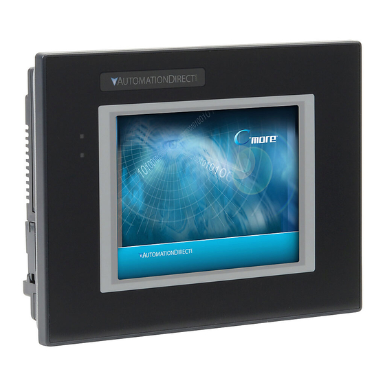
Chapter 1 - Getting Started Product Overview Some of the features designed into the product to provide excellent hardware and software are listed below. • Analog touch screen (no touch cell boundaries). The touchscreen is designed to respond to a single touch. -
Page 22: Quick Start Steps
Cutout Template* c.) Inspect all equipment for completeness. If anything is missing C-more Panel or damaged, immediately call the AutomationDirect® returns Gasket department @ 1-800-633-0405. DC power connector Mounting Clips Logo Label* *Not included with EA9-T7CL-R and EA9-T7CL. -
Page 23: Step 2 - Install Optional Hardware Accessories
Chapter 1 - Getting Started Step 2 – Install Optional Hardware Accessories EA-AC EA-ECOM AC / DC Power Adapter Expansion Module EA-COMCON-3A DSUB Port Adapter EA-SD-CARD SD Card USB-FLASH USB Pen Drive C-more Touch Panel EA-x-COV2 Screen Protector EA9-USER-M Hardware User Manual, 1st Ed. Rev. K ®... -
Page 24: Step 3 - Become Familiar With Available Communication Ports
Chapter 1 - Getting Started Step 3 – Become Familiar with Available Communication Ports Port 2 Serial Communication RS-485 – Logic Ground SD Card Slot 1 SD Card Slot 2 Port 3 RJ12 Serial Communication RS-232C Signal N.C. USB Port - Type B Programming Signal N.C. -
Page 25: Step 4 - Install The Programming Software And Develop A Project
Download the latest version of the C-more Programming Software, p/n EA9-PGMSW, from the Automationdirect website. Alternately, if the C-more Programming Software CD is available, you may install from the software CD. Refer to the AutomationDirect website for current minimum system requirements for installation. -
Page 26: Step 5 - Connect Touch Panel To Computer
Chapter 1 - Getting Started Step 5 – Connect Touch Panel to Computer • Connect a USB Programming Cable, such as p/n USB-CBL-AB15, from a USB type A port on the PC to the USB type B programming port on the C-more touch panel •... -
Page 27: Step 6 - Provide Power To The Touch Panel
Chapter 1 - Getting Started Step 6 – Provide Power to the Touch Panel • Connect a dedicated 12-24 VDC Class 2 power supply to the DC connector on the rear of the C-more touch panel, include wiring the ground terminal to a proper equipment ground •... - Page 28 Chapter 1 - Getting Started Step 6 – Provide Power to the Touch Panel (cont’d) C-more LED Status Indicators User Defined LED (Green, Orange & Red) Power LED (Green) Green Power On Power Off User Defined Orange (Refer to online help file for further details) Blinking Blinking...
-
Page 29: Step 7 - Access The Touch Panel Setup Screens
Chapter 1 - Getting Started Step 7 – Access the Touch Panel Setup Screens • Access the Main Menu of the touch panel System Setup Screens by pressing the extreme upper left corner of the panel display area for three (3) seconds as shown below. •... -
Page 30: Step 8 - Choose Touch Panel To Device Cables
Modbus (Koyo addressing) Direct NET D2-240/D2-250-1/D2-260 Using DCM Modbus (Koyo addressing) H2-ECOM/H2-ECOM100 Direct LOGIC Ethernet Direct NET D3-330/330P (Requires the use of a Data Communications Unit) AutomationDirect D3-340 Direct NET K-Sequence DL305 D3-350 Direct NET Modbus (Koyo addressing) Direct NET... - Page 31 Chapter 1 - Getting Started Step 8 – Choose Touch Panel to Device Cables (cont’d) PLC Protocol Table (cont’d) Model Protocols MicroLogix 1000, 1100, 1200, 1400, 1500, SLC 5-01/02/03 DH485/AIC/AIC+ MicroLogix 1000, 1100, 1200, 1400 and 1500 SLC 5-03/04/05 DF1 Half Duplex; DF1 Full Duplex ControlLogix™, CompactLogix™, FlexLogix™...
-
Page 32: Allen-Bradley ������������������������������������������������������������������������������������������������������������
See Chapter 6: PLC Communications for wiring diagrams of additional user contructed cables. Purchased Cable Cable Description Part Number AutomationDirect Productivity Series, Do-more, CLICK, EA-2CBL Direct LOGIC PLC RJ-12 port, DL05, DL06, DL105, DL205, D3-350, D4-450 & H2-WINPLC (RS-232C) Direct LOGIC (VGA Style) 15-pin port EA-2CBL-1... -
Page 33: Step 9 - Connect Touch Panel To Plc
Chapter 1 - Getting Started Step 9 – Connect Touch Panel to PLC • Connect the serial communications cable between the C-more touch panel and the PLC • or connect the C-more touch panel and PLC together either directly or via an Ethernet switch, and CAT5 Ethernet cables (full feature panels only) For further information on setting up communications between a C-more panel and a PLC, see the C-more programming help file topic CM129: Creating a New Project. - Page 34 hapter hapter hapter pecificationS In This Chapter... Available Models ......................2-4 Model Specifications .....................2-5 Specifications common to all models ���������������������������������������������������������������������������2-6 6-inch Models ��������������������������������������������������������������������������������������������������������������2-7 7-inch Models ��������������������������������������������������������������������������������������������������������������2-8 8-inch and 10-inch Models ������������������������������������������������������������������������������������������2-9 12-inch and 15-inch Models ��������������������������������������������������������������������������������������2-10 EA9-T6CL-R, EA9-T6CL ....................2-11 Dimensions, Inches [mm] �������������������������������������������������������������������������������������������2-11 Ports and Memory Expansion �������������������������������������������������������������������������������������2-12 EA9-T7CL-R, EA9-T7CL ....................2-13 Dimensions, Inches [mm] �������������������������������������������������������������������������������������������2-13...
- Page 35 hapter hapter hapter pecificationS EA9-T12CL ........................2-20 Dimensions, Inches [mm] ������������������������������������������������������������������������������������������ 2-20 Ports and Memory Expansion ������������������������������������������������������������������������������������ 2-21 EA9-T15CL-R, EA9-T15CL .................... 2-22 Dimensions, Inches [mm] ������������������������������������������������������������������������������������������ 2-22 Ports and Memory Expansion ������������������������������������������������������������������������������������ 2-23 Mounting Clearances ....................2-25 EA9-T15CL-R, EA9-T15CL Derating ��������������������������������������������������������������������������� 2-26 Communications Ports ....................
- Page 36 This page intentionally left blank...
-
Page 37: Chapter 2: Specifications
Available Models The C-more® Operator Interface is the next generation of touch panel brought to you by AutomationDirect. It has been designed to display and interchange graphical data from a PLC by merely viewing or touching the screen. The C-more Touch Panel is available in a variety of models to suit your application. Refer to the following tables for a list of part numbers, descriptions and options available. -
Page 38: Model Specifications
Chapter 2 - Specifications Model Specifications The following specification tables are separated into these groups: • Specifications common to all models • 6” & 7” Reduced and Full Feature Models, EA9-T6CL-R, EA9-T6CL, EA9-T7CL-R and EA9-T7CL • 8” & 10” Full Feature Models, EA9-T8CL, EA9-T10CL and EA9-T10WCL •... -
Page 39: Specifications Common To All Models
Chapter 2 - Specifications Specifications common to all models Model All Models Specification 0 to 50 °C (32 to 122 °F); Maximum surrounding air temperature rating: 50 °C (122 °F) Operating Temperature IEC 60068-2-14 (Test Nb, Thermal Shock) Altitude Up to 2000m (6562 ft) –20 to +60 °C (–4 to +140 °F) IEC 60068-2-1 (Test Ab, Cold) Storage Temperature... -
Page 40: 6-Inch Models
Chapter 2 - Specifications 6-inch Models Model 6” TFT color w/ 6” TFT color w/ base features full features Specification Part Number EA9-T6CL-R EA9-T6CL Display Actual Size and Type 5.7” TFT color 4.54” x 3.40” Display Viewing Area [115.2 mm x 86.4 mm] Weight 1.56 lb (710g) 1.59 lb (720g) -
Page 41: 7-Inch Models
Chapter 2 - Specifications 7-inch Models Model 7” TFT color w/ 7” TFT color w/ base features full features Specification Part Number EA9-T7CL-R EA9-T7CL Display Actual Size and Type 7.0” TFT color 6.0” x 3.60” Display Viewing Area [152.4 mm x 91.4 mm] Weight 1.46 lb (660g) 1.48 lb (670g) -
Page 42: 8-Inch And 10-Inch Models
Chapter 2 - Specifications 8-inch and 10-inch Models Model 8” TFT color w/ 10” TFT color w/ 10” TFT color widescreen w/ full features Specification full features full features Part Number EA9-T8CL EA9-T10CL EA9-T10WCL Display Actual Size and Type 8.4” TFT color 10.4”... -
Page 43: 12-Inch And 15-Inch Models
Chapter 2 - Specifications 12-inch and 15-inch Models Model 12” TFT color w/ 15” TFT color w/ 15” TFT color w/ Specification full features base features full features Part Number EA9-T12CL EA9-T15CL-R EA9-T15CL Display Actual Size and Type 12.1” TFT color 15.0”... -
Page 44: Ea9-T6Cl-R, Ea9-T6Cl
Chapter 2 - Specifications EA9-T6CL-R, EA9-T6CL Dimensions, Inches [mm] All the necessary mounting hardware is provided with the touch panel. Use the four mounting clips and screws to secure the touch panel to the cabinet or enclosure surface. A template for marking the cutout dimensions on the mounting surface is provided in the box. Enclosure Mounting Thickness Ranges and Mounting Clip Screw Torque Touch... -
Page 45: Ports And Memory Expansion
Chapter 2 - Specifications Ports and Memory Expansion EA9-T6CL-R EA9-T6CL 2-12 EA9-USER-M Hardware User Manual, 1st Ed. Rev. K ®... -
Page 46: Ea9-T7Cl-R, Ea9-T7Cl
Chapter 2 - Specifications EA9-T7CL-R, EA9-T7CL Dimensions, Inches [mm] All the necessary mounting hardware is provided with the touch panel. Use the four mounting clips and screws to secure the touch panel to the cabinet or enclosure surface. A template for marking the cutout dimensions on the mounting surface is provided in the box. Enclosure Mounting Thickness Ranges and Mounting Clip Screw Torque Touch... -
Page 47: Ports And Memory Expansion
Chapter 2 - Specifications Ports and Memory Expansion EA9-T7CL-R EA9-T7CL 2-14 EA9-USER-M Hardware User Manual, 1st Ed. Rev. K ®... -
Page 48: Ea9-T8Cl
Chapter 2 - Specifications EA9-T8CL Dimensions, Inches [mm] All the necessary mounting hardware is provided with the touch panel. Use the four mounting clips and screws to secure the touch panel to the cabinet or enclosure surface. A template for marking the cutout dimensions on the mounting surface is provided in the box. Enclosure Mounting Thickness Ranges and Mounting Clip Screw Torque Touch... -
Page 49: Ports And Memory Expansion
Chapter 2 - Specifications Ports and Memory Expansion EA9-T8CL 2-16 EA9-USER-M Hardware User Manual, 1st Ed. Rev. K ®... -
Page 50: Ea9-T10Cl
Chapter 2 - Specifications EA9-T10CL Dimensions, Inches [mm] All the necessary mounting hardware is provided with the touch panel. Use the eight mounting clips and screws to secure the touch panel to the cabinet or enclosure surface. A template for marking the cutout dimensions on the mounting surface is provided in the box. Enclosure Mounting Thickness Ranges and Mounting Clip Screw Torque Touch... -
Page 51: Ea9-T10Wcl
Chapter 2 - Specifications EA9-T10WCL Dimensions, Inches [mm] All the necessary mounting hardware is provided with the touch panel. Use the eight mounting clips and screws to secure the touch panel to the cabinet or enclosure surface. A template for marking the cutout dimensions on the mounting surface is provided in the box. Enclosure Mounting Thickness Ranges and Mounting Clip Screw Torque Touch... -
Page 52: Ports And Memory Expansion
Chapter 2 - Specifications Ports and Memory Expansion EA9-T10CL EA9-T10WCL 2-19 EA9-USER-M Hardware User Manual, 1st Ed. Rev. K ®... -
Page 53: Ea9-T12Cl
Chapter 2 - Specifications EA9-T12CL Dimensions, Inches [mm] All the necessary mounting hardware is provided with the touch panel. Use the eight mounting clips and screws to secure the touch panel to the cabinet or enclosure surface. A template for marking the cutout dimensions on the mounting surface is provided in the box. Enclosure Mounting Thickness Ranges and Mounting Clip Screw Torque Touch... -
Page 54: Ports And Memory Expansion
Chapter 2 - Specifications Ports and Memory Expansion EA9-T12CL 2-21 EA9-USER-M Hardware User Manual, 1st Ed. Rev. K ®... -
Page 55: Ea9-T15Cl-R, Ea9-T15Cl
Chapter 2 - Specifications EA9-T15CL-R, EA9-T15CL Dimensions, Inches [mm] All the necessary mounting hardware is provided with the touch panel. Use the eight mounting clips and screws to secure the touch panel to the cabinet or enclosure surface. A template is provided for marking the cutout dimensions on the mounting surface. Enclosure Mounting Thickness Ranges and Mounting Clip Screw Torque Touch... -
Page 56: Ports And Memory Expansion
Chapter 2 - Specifications Ports and Memory Expansion EA9-T15CL-R 2-23 EA9-USER-M Hardware User Manual, 1st Ed. Rev. K ®... - Page 57 Chapter 2 - Specifications EA9-T15CL 2-24 EA9-USER-M Hardware User Manual, 1st Ed. Rev. K ®...
-
Page 58: Mounting Clearances
Chapter 2 - Specifications Mounting Clearances The following drawing shows the mounting clearances for the C-more touch panel. There should be a minimum of 4 inches of space between all sides of the panel and the nearest object or obstruction and at least 1.72 inches between the rear of the panel and the nearest object or obstruction. -
Page 59: Ea9-T15Cl-R, Ea9-T15Cl Derating
Chapter 2 - Specifications EA9-T15CL-R, EA9-T15CL Derating If EA9-T15CL-R and EA9-T15CL are mounted off the vertical plane facing upward, the temperature shall be derated as shown below. Other panels may be mounted at any angle without derating consideration. 90° EA9-T15CL-R, EA9-T15CL Angle: -15°... -
Page 60: Communications Ports
FTP access, and allowing users to access and control the panel remotely. The Ethernet connector is an RJ-45 Module jack. NOTE: EA9-T6CL-R does not include an Ethernet port and does not have these capabilities. Refer to http://c-more.automationdirect.com for the latest driver information. 2-27 EA9-USER-M Hardware User Manual, 1st Ed. Rev. K... -
Page 61: Communications Ports
Chapter 2 - Specifications Communications Ports (cont’d) USB Type B Port Program C-more via the USB programming port. It’s fast and easy, with no baud rate settings, parity, or stop bits to worry about. We stock standard USB cables for your convenience, such as part no. - Page 62 Chapter 2 - Specifications Serial Communication Ports Port 1 Connect to your serial controller network via Port 1. Port 1 is a 15-pin port that supports RS-232 and RS-422/485. Port 2 Connect your RS-485 network via Port 2. Port 2 is provided with a 3-wire removable terminal block.
-
Page 63: Handling External Memory Devices
Chapter 2 - Specifications Handling External Memory Devices Writing to External Memory Devices Different types of numeric and text data from the C-more touch panel can be stored on an SD card or a USB memory device. Numeric data from Line Trend Graph and PID Faceplate Trend Graph objects may be stored. -
Page 64: Minimizing Data Errors
Chapter 2 - Specifications Minimizing Data Errors To minimize data errors when logging data to external memory, consider the following: C-more • Do not turn off power to the touch panel while the external memory device is being accessed. The optional EA-AC power adapter is designed to protect external memory devices from damage during power failure. -
Page 65: File Name Limitations
File Name Limitations There is a limit of 999 file names with the same first four characters. Internal file names are restricted by the DOS 8-character-dot-3-character limit. Therefore trend log files are identified internally by the first four characters of the object name plus tilde plus a three digit number. Examples are: TREND GRAPH EAST CHILLER TEMP_130925.txt is saved internally as TREN~001.txt TREND GRAPH WEST CHILLER TEMP_130925.txt is saved internally as TREN~002.txt... - Page 66 hapter hapter hapter ccessories In This Chapter... Accessories Overview ....................3-2 AC/DC Power Adapter ....................3-3 AC/DC Power Adapter Dimensions �������������������������������������������������������������������������� 3-5 AC/DC Power Adapter Installation ���������������������������������������������������������������������������� 3-6 EA-ECOM Ethernet Communication Module ............3-7 D-SUB 15-pin to Terminal Block Adapters ..............3-8 Non-glare Screen Covers ...................
-
Page 67: Accessories Overview
Chapter 3 - Accessories Accessories Overview EA-COMCON-3A EA-ECOM DSUB Port Adapter Expansion Module EA-AC AC / DC Power Adapter EA-SD-CARD SD Card USB-FLASH USB Pen Drive C-more Touch Panel EA-x-COV2 Screen Protector Part Number Description EA-AC AC/DC power adapter, 24 VDC. For use with C-more EA7 and EA9 series touch panels. EA-6-COV2 Screen protector, non-glare, 6in. -
Page 68: Ac/Dc Power Adapter
Chapter 3 - Accessories AC/DC Power Adapter The optional C-more AC/DC Power Adapter can be used to power the C-more touch panels from a 100-240 VAC, 50/60 Hertz, voltage source. The adapter provides 24 VDC @ 1.5 A to the touch panel’s DC power connector and can be conveniently secured to the touch panel with two captive screws. - Page 69 Chapter 3 - Accessories AC/DC Power Adapter Specifications Part Number EA-AC Input Voltage & frequency 100-240 VAC; 50/60 Hertz Operating Temperature Range 0 °C to 50 °C [32 to 122 °F] Maximum surrounding temperature rating, 50 °C Storage Temperature Range -20 to 60 °C [-4 to 140 °F] Operating &...
-
Page 70: Ac/Dc Power Adapter Dimensions
Chapter 3 - Accessories AC/DC Power Adapter Dimensions Dimensions AC Power Label Screw 3.661 [93.0] 3.001 [76.2] DC Power Connector Screw FRONT VIEW SIDE VIEW REAR VIEW AC Power Connector Units: inches [mm] 1.421 ±0.02 [36.1 ± 0.5 0.579 [14.7] BOTTOM VIEW Panel Depth with AC/DC Power Adapter Installed Units: inches[mm]... -
Page 71: Ac/Dc Power Adapter Installation
Chapter 3 - Accessories AC/DC Power Adapter Installation WARNING: This procedure should only be performed by qualified personnel who are experienced in working with electronic equipment. Take the necessary steps to prevent damage that may be caused by static electricity discharge. Disconnect input power to the touch panel before proceeding. Preparation: Place the touch panel face down on a lint-free soft Insert the AC/DC power adapter into the touch panel’s 5-position DC surface to prevent scratching the display screen if not already installed... -
Page 72: Ea-Ecom Ethernet Communication Module
PLC communications at a speed of 10/100 Mbps. EA-ECOM Dimensions: Inches [mm] PLC Drivers AutomationDirect Productivity Series Ethernet AutomationDirect Do-more / BRX Ethernet AutomationDirect CLICK Ethernet AutomationDirect ECOM Ethernet Modbus TCP/IP Allen-Bradley EtherNet/IP (Client) SLC5/05 Allen-Bradley EtherNet/IP (Client) ENI Adapter... -
Page 73: D-Sub 15-Pin To Terminal Block Adapters
Chapter 3 - Accessories D-SUB 15-pin to Terminal Block Adapters These adapters are plugged into the 15-pin serial port on the rear of the panels to allow wire terminal connections for RS-422/485 PLC communication cable. The wiring of both adapters is the same. EA-COMCON-3 is used with EA9-T6CL-R, EA9-T6CL, EA9-T7CL-R and EA9-T7CL. -
Page 74: Non-Glare Screen Covers
Chapter 3 - Accessories Non-glare Screen Covers Non -glare PET screen covers are protective overlays used to protect the touch screen and help reduce glare from external light sources. (pk of 3) Part No. EA-6-COV2, EA-7-COV2, EA-8-COV2, EA-10-COV2, EA-10W-COV2, EA-12-COV2 & EA-15-COV2 EA-xx-COV2 Non-glare Screen Covers Dimensions - inches [mm] Part Number... -
Page 75: Clear Screen Overlay Installation
Chapter 3 - Accessories Non-glare Screen Covers (cont’d) Clear Screen Overlay Installation Step 1 Step 2 Check to be sure that the proper size non-glare screen cover is being used on the subject touch panel. Notice that the outer perimeter of the screen cover has an adhesive band. -
Page 76: Sd Card
Recommended for C-more EA9 series. The EA-SD-CARD utilizes SLC technology so it is the fastest option for writing and storing data. If logged data is saved to external memory, AutomationDirect recommends using an EA-SD-CARD. - Page 78 hapter hapter hapter nstallatIon and IrIng In This Chapter... Safety Guidelines ......................4-2 Introduction ........................4-3 EA9-T6CL-R, EA9-T6CL, EA9-T7CL-R and EA9-T7CL Cutout Dimensions ......................4-4 EA9-T8CL and EA9-T10WCL Cutout Dimensions ............4-5 EA9-T12CL Cutout Dimensions ..................4-7 EA9-T15CL-R and EA9-T15CL Cutout Dimensions ............4-8 Mounting Clearances ....................4-9 EA9-T15CL-R, EA9-T15CL Derating ����������������������������������������������������������������������������4-10 Wiring Guidelines ......................4-11 Agency Approvals �������������������������������������������������������������������������������������������������������4-11...
-
Page 79: Chapter 4: Installation And Wiring
The protection provided by the equipment may be impaired if this equipment is used in a manner not specified in this manual. A listing of our international affiliates is available on our Web site: http://www. automationdirect.com WARNING: Providing a safe operating environment for personnel and equipment is your responsibility and should be your primary goal during system planning and installation. -
Page 80: Introduction
Chapter 4 - Installation and Wiring Introduction The installation and wiring of the C-more® touch panels requires selecting an appropriate location for the touch panel, laying out the cutout dimensions on the surface of the control cabinet that the panel will be mounted through, securing the touch panel with the provided mounting clips, tightening the screws to the appropriate torque rating to assure the gasket is sealing correctly, and finally connecting the appropriate power source to the touch panel. -
Page 81: Ea9-T6Cl-R, Ea9-T6Cl, Ea9-T7Cl-R And Ea9-T7Cl Cutout Dimensions
Chapter 4 - Installation and Wiring EA9-T6CL-R, EA9-T6CL, EA9-T7CL-R and EA9-T7CL Cutout Dimensions The C-more 6” and 7” touch panels are mounted into a cutout through the control cabinet and secured with four (4) mounting clips. The mounting clips are provided with the touch panel. -
Page 82: Ea9-T8Cl And Ea9-T10Wcl Cutout Dimensions
Chapter 4 - Installation and Wiring EA9-T8CL and EA9-T10WCL Cutout Dimensions The C-more EA9-T8CL and EA9-T10WCL touch panels will mount into the same cutout and are mounted into the cutout through the control cabinet and secured with four (4) mounting clips. The mounting clips are provided with the touch panel. The mounting clips will insert into a series of slots around the rear perimeter of the touch panel. - Page 83 Chapter 4 - Installation and Wiring EA9-T10CL Cutout Dimensions The C-more 10” touch panels are mounted into a cutout through the control cabinet and secured with eight (8) mounting clips. The mounting clips are provided with the touch panel. The mounting clips will insert into a series of slots around the rear perimeter of the touch panel.
-
Page 84: Ea9-T12Cl Cutout Dimensions
Chapter 4 - Installation and Wiring EA9-T12CL Cutout Dimensions The C-more 12” touch panels are mounted into a cutout through the control cabinet and secured with eight (8) mounting clips. The mounting clips are provided with the touch panel. The mounting clips will insert into a series of slots around the rear perimeter of the touch panel. -
Page 85: Ea9-T15Cl-R And Ea9-T15Cl Cutout Dimensions
Chapter 4 - Installation and Wiring EA9-T15CL-R and EA9-T15CL Cutout Dimensions The C-more 15” touch panels are mounted into a cutout through the control cabinet and secured with eight (8) mounting clips. The mounting clips are provided with the touch panel. The mounting clips will insert into a series of slots around the rear perimeter of the touch panel. -
Page 86: Mounting Clearances
Chapter 4 - Installation and Wiring Mounting Clearances The following drawing shows the mounting clearances for the C-more touch panel. There should be a minimum of 4 inches of space between all sides of the panel and the nearest object or obstruction and at least 1.72 inches between the rear of the panel and the nearest object or obstruction. -
Page 87: Ea9-T15Cl-R, Ea9-T15Cl Derating
Chapter 4 - Installation and Wiring EA9-T15CL-R, EA9-T15CL Derating If EA9-T15CL-R and EA9-T15CL are mounted off the vertical plane facing upward, the temperature shall be derated as shown below. Other panels may be mounted at any angle without derating consideration. 90°... -
Page 88: Wiring Guidelines
This publication is based on information that was available at the time it was printed. At Automationdirect.com® we constantly strive to improve our products and services, so we reserve the right to make changes to the products and/or publications at any time without notice and without obligation. -
Page 89: Providing Power To The Touch Panel
Chapter 4 - Installation and Wiring Wiring Guidelines (cont’d) Providing Power to the Touch Panel • Connect a dedicated 12-24 VDC Class 2 power supply to the DC connector on the rear of the C-more touch panel, include wiring the ground terminal to a proper equipment ground •... -
Page 90: C-More Led Status Indicators
Chapter 4 - Installation and Wiring C-more LED Status Indicators User Defined LED (Green, Orange & Red) Power LED (Green) Green Power On Power Off User Defined Orange (Refer to online help file for further details) Blinking Blinking Orange Blinking Green Front View CPU Status LED (Green, Orange &... - Page 92 hapter hapter hapter yStem etup creenS In This Chapter... Introduction ........................5-2 Accessing the System Setup Screens (no project loaded) ...........5-3 Accessing the System Setup Screens (with project loaded) ........5-4 System Setup Screens – Enable Password in Software ..........5-6 System Setup Screens Flowchart ................5-12 Main Menu........................5-13 Information Menu .......................5-14 Setting Menu .......................5-18...
-
Page 93: Chapter 5: System Setup Screens
Chapter 5 - System Setup Screens Introduction The C-more touch panels include a series of built-in System Setup Screens that allow the user to view detailed information about the panel; adjust certain features; configure communications; test various functions of the touch panel; backup & restore firmware, recipe, log and project memory;... -
Page 94: Accessing The System Setup Screens (No Project Loaded)
Chapter 5 - System Setup Screens Accessing the System Setup Screens (no project loaded) To access the Main Menu of the touch panel System Setup Screens prior to downloading a project, press the extreme upper left corner of the panel display area for 3 seconds as shown below. -
Page 95: Accessing The System Setup Screens (With Project Loaded)
Chapter 5 - System Setup Screens Accessing the System Setup Screens (with project loaded) To access the Main Menu of the touch panel System Setup Screens with a project loaded into memory, press the upper left corner of the panel display area for 3 seconds as shown below. If no system screen password is enabled, the following WARNING dialog box will appear on the touch screen.: •... - Page 96 Chapter 5 - System Setup Screens System Setup Screens The OK button in the Warning dialog box will bring up the Main Menu as shown below. You can then proceed to the other system setup screens. Password Protecting System Screen Access NOTE: If the password system tag SYS SYSTEMSCREENPW is enabled, the Enter Security Code keypad shown below will open.
-
Page 97: System Setup Screens - Enable Password In Software
Chapter 5 - System Setup Screens System Setup Screens – Enable Password in Software Under the C-more Programming Software’s Navigation window, select the Function tab, then double click on “Alarm Action” to display the Event Manager Database shown below: Click on the Add button to add an event to the database that will be used to enable the System... - Page 98 Chapter 5 - System Setup Screens System Setup Screens – Enable Password (cont’d) The Event Add dialog box will be displayed as shown. Click on the Tag Name: pull down menu and select the internal System Bit On (SYS BIT ON) tag as shown. This will force the tag event type to be continuously active. Tag Name: SYS BIT ON EA9-USER-M Hardware User Manual, 1st Ed.
- Page 99 Chapter 5 - System Setup Screens System Setup Screens – Enable Password (cont’d) Use the Event Name: text box to document the event as “System Screen PW” for record keeping This is optional. In the Action box, click once on the displayed 01-Alarm under the Sequence List: so that 01-Alarm is highlighted.
- Page 100 Chapter 5 - System Setup Screens System Setup Screens – Enable Password (cont’d) In the Action box, click on the Add Action... button. This will bring up the Add Action dialog box as shown below: Add Action Click on the Command: pull down list in the Add Command box, select Tag from the list, then click OK.
- Page 101 Chapter 5 - System Setup Screens System Setup Screens – Enable Password (cont’d) A 01-Tag action item will then be added to the Sequence List. 01-Tag Click on the Tag Name: pull down list down arrow in the Action box’s Tag tab, select SYS SYSTEMSCREENPW from the list, and click OK.
- Page 102 Chapter 5 - System Setup Screens System Setup Screens – Enable Password (cont’d) Enter a numeric value into the Value: box, such as “777”. This value becomes the Password code to access the System Setup Screen’s Main Menu. Password Value – 777 Click the Apply button in the Event Add dialog box and then the Close button to return to the Event Manager Database.
-
Page 103: System Setup Screens Flowchart
Chapter 5 - System Setup Screens System Setup Screens Flowchart Main Menu General/Memory/Ethernet/ Information Error Setting Adjust Clock Adjust Display IP Address Setting Adjust Touch Panel (Touch Screen Calibration) Beep Mouse Test Menu Test Touch Panel Test Display Test User LED Test Communication Port Test Beep/Sound Memory... -
Page 104: Main Menu
Chapter 5 - System Setup Screens Main Menu The Main Menu system setup screen is the top layer in the menu structure. Touch Screen Calibration While the Main Menu system setup screen is being displayed, the extreme upper left corner of the touch panel can be pressed for 3 seconds to access the Touch Screen Calibration display. -
Page 105: Information Menu
Chapter 5 - System Setup Screens Information Menu Information - General tab The General tab under the Information menu provides detailed information of the C-more touch panel. Item No. Function Description Comments EA9-T6CL-R EA9-T6CL EA9-T7CL-R EA9-T7CL EA9-T8CL Panel Type Model Number EA9-T10CL EA9-T10WCL EA9-T12CL... - Page 106 Chapter 5 - System Setup Screens Information - Memory tab 1. Memory components - Status of each memory component - SDRAM, MRAM and Built-in Flash are internal memory components. When external memory devices are installed in the panel they will be included in this list : SD1, SD2 (12 and 15 inch panels only) and USB.
- Page 107 Chapter 5 - System Setup Screens Information - Ethernet tab Item No. Function Description Comment Ethernet Settings: MAC Address: 00 D0 7C XX XX XX Address Type: DHCP/Static IP Address: Configurable in the Setting Menu Ethernet – IP Address Setting shown on Subnet Mask: (Link: Online) in this section or in the C-more...
- Page 108 Chapter 5 - System Setup Screens Information - Error tab Error message format Navigation buttons Error Message Format: Item No. Function Description Comment Order of error message functions: Error Number, Date, Time, Error Port, Device Name, Error Type, PLC Device, Access Bytes, Error Message Date Format: MM/DD/YY Date error occurred.
-
Page 109: Setting Menu
Chapter 5 - System Setup Screens Setting Menu The Setting Menu is used to adjust the time & date, adjust the contrast or brightness of the display, enter the IP address settings, adjust (calibrate) the touch screen, enable or disable the internal beep and turn on and off the mouse cursor . - Page 110 Chapter 5 - System Setup Screens Setting – Adjust Clock Item No. Function Description Comments Time: Each press of the Select button will cycle thru the following settings. 1.) No Selection to Hours 2.) Hours to Minutes 3.) Minutes to Seconds 4.) Seconds back to Hours Select Date: Each press of the Select button will...
- Page 111 Chapter 5 - System Setup Screens Setting – Adjust Display Item No. Function Description Comments Use the Up and Down arrows to change the Setting brightness. Displays a sample of how colors will appear Color Sample with the new setting. Displays a sample of contrast with the new Contrast Sample setting...
- Page 112 Chapter 5 - System Setup Screens Setting – Adjust Touch Panel This procedure is used to calibrate the touch screen to ensure accuracy of the touch areas. There are five points on the touch screen that the calibration is based around. The adjustment relies on very narrow areas for the calibration points.
- Page 113 Chapter 5 - System Setup Screens Setting – Beep This system setup screen function is used to enable or disable the touch panel’s internal beep function. Item No. Function Description Comments Enable Beep Check to enable the internal beep. Press to accept the changes. Press to return to the Setting Menu screen Cancel without accepting the changes.
- Page 114 Chapter 5 - System Setup Screens Setting – Mouse This system setup screen function is used to enable/ disable the arrow mouse cursor on the panel screen. It may be valuable to display the mouse cursor, for example, when an external USB keyboard is connected to the panel..
- Page 115 Chapter 5 - System Setup Screens Setting – IP Address Setting Item No. Function Description Comment “DHCP” is enabled as the default when this system setup screen is first selected. DHCP All of the other selections on this screen are dimmed when “DHCP”...
-
Page 116: Test Menu
Chapter 5 - System Setup Screens Test Menu The Test Menu gives the user the ability to test the operation of the touch screen, test the LCD display, test the various communication ports, and also test the internal beeper and the audio line out through an user supplied amplified (stereo) speaker(s). - Page 117 Chapter 5 - System Setup Screens Test Menu – Test Touch Panel Using this test, normal or unusual operation of the analog touch panel can be determined. Testing: If an area of the touch screen is suspected to be inoperable, touch that area of the screen while in the Test Touch Panel screen mode.
- Page 118 Chapter 5 - System Setup Screens Test Menu – Test Display There are two different test patterns that may be run on the display to allow the user to check for display screen defects. If the screen is not touched within 3 seconds of Test Pattern 1 being displayed, then Test Pattern 2 will be displayed until the screen is touched, otherwise Test Pattern 1 will remain until cancelled.
- Page 119 Chapter 5 - System Setup Screens Test Menu – Test Communication Ports: Serial Ports The following test can be used to check the operation of the serial communication ports, with the use of a loop back connector and can also check the serial communications to any connected and configured PLC.
- Page 120 Chapter 5 - System Setup Screens Test Menu – PLC Serial Comm Port – Loop Back Test Test Results 1.) Bytes Sent: The number of bytes sent after a test is started. 2.) Receive Counts: The number of bytes which are received after the test is started. 3.) Error Counts: The number of bytes which have not been received after the test is started.
- Page 121 Chapter 5 - System Setup Screens Test Menu – PLC Enquiry Test: Serial Connection This function allows the ability to select any PLC that may be connected to the touch panel through the selected serial comm. port connection and checks to see if the communications are working correctly.
- Page 122 Chapter 5 - System Setup Screens Test Menu – Test Communication Ports: Ethernet The following test feature can be used to check the operation of the Ethernet communication port by indicating if an Ethernet link has been established or not, and can also check the status of the Ethernet communications to any connected PLC.
- Page 123 Chapter 5 - System Setup Screens Test Menu – PLC Enquiry Test: Ethernet Connection This function allows the ability to select any PLC configured in the project that may be connected to the touch panel through an Ethernet port connection and checks to see if the communications are working correctly.
- Page 124 Chapter 5 - System Setup Screens Test Menu – Test Beep/Sound The internal Beeper can be tested from this system setup screen whether the Beeper is enabled or disabled. After the Beep Test button is pressed and released, the Beeper will sound for 500 msec. The Speaker Test function requires that a speaker(s) with an amplifier (can be stereo) be connected to the Audio Line Out stereo jack on the rear of the touch...
-
Page 125: Memory Menu
Chapter 5 - System Setup Screens Memory Menu The user’s project, Firmware and OS, log and recipes files can be backed up to or restored from an SD memory card (SD Card Slot 1 or SD Card Slot 2), or a USB memory device. - Page 126 Chapter 5 - System Setup Screens Project Executed from SD Card Slot 1 If the Project Storage/Boot Location is set to Auto or SD1 in the C-more software Panel Manager, and an SD memory card is located in the SD Card Slot 1 at the time a project is transferred to the panel, the project will be stored on the SD card, and the Internal Project Memory will be cleared.
- Page 127 Chapter 5 - System Setup Screens Memory – Backup The Memory - Backup selection allows you to backup the panel’s Project, Log files, Recipe files or even the Firmware files to either an SD memory card or USB pen drive. The available memory devices will be displayed with their total and free memory.
- Page 128 Chapter 5 - System Setup Screens Memory – Backup (cont’d) SD Card Slot1 Availability Explanation: SD1 may be unavailable (grayed out) if there is no card in SD Slot 1 or the card in SD slot 1 has the project currently running on the panel stored on it.
- Page 129 Chapter 5 - System Setup Screens Memory – Backup (cont’d) NOTE: The following definitions are for the various file types that can be backed up: Project data – consists of the actual developed project data that is created in the C-more programming software and includes all functionality, objects, screens, tag names, labels, comments, graphics, etc.
- Page 130 Chapter 5 - System Setup Screens Memory – Backup (cont’d) Backup Data Files Naming and Organization The following graphic shows how the various data files are organized on the memory device when doing a Backup and also the file naming convention that is used when viewed in Windows®...
- Page 131 Chapter 5 - System Setup Screens Memory – Backup (cont’d) The next system setup screen allows the verification of the data file selections. When the OK button is pressed, the backup begins. The user can return to the previous screen by pressing the <<...
- Page 132 Chapter 5 - System Setup Screens Memory – Backup (cont’d) Warning Messages If the destination does not have enough space to store the selected memory size, then the message shown here will be displayed. Press the OK button to clear the warning message.
- Page 133 Chapter 5 - System Setup Screens Memory – Restore The Memory - Restore function is used to: 1.) Restore a project previously backed up on an SD card or USB pen drive memory device to the same panel. See Memory - Backup previously in this chapter.
- Page 134 Chapter 5 - System Setup Screens Memory – Restore (cont’d) Please read the explanation for the availability of SD1 under different conditions as shown on this page and the next. SD1 Availability Explanation: SD1 may be unavailable (grayed out) if there is no card in SD Slot 1 or the card in SD slot 1 has the project currently running on the panel stored on it.
- Page 135 Chapter 5 - System Setup Screens Memory – Restore (cont’d) Select the data file(s) to be restored by pressing the Restore appropriate data file button. The selection will be highlighted. The data file can be either the Project, Step–2 : Select Data Area to Restore Firmware and/or Recipe files.
- Page 136 Chapter 5 - System Setup Screens Memory – Restore (cont’d) The data selected to restore is checked. If the data is good, then the OK button can be pressed to start the restore. If there is a problem with the data, the OK button will remain grayed out and the user can return to the previous screen by pressing the <<...
- Page 137 Chapter 5 - System Setup Screens Memory – Restore (cont’d) Warning Messages: If the system memory does not have enough space to restore the selected memory size, then the message shown here will be displayed. Press the OK button to clear the warning message.
- Page 138 Chapter 5 - System Setup Screens Memory – Clear Memory This function is used to clear individually selected data files, or all data files, within the panel’s Built-in Memory, or any installed memory device such as a USB pen drive or an SD card. Select the memory device to clear.
- Page 139 Chapter 5 - System Setup Screens Memory – Clear Memory (cont’d) Select the data file(s) to be cleared. Clear Memory This is an example of an SD card or USB memory Step–2 : Select Data Area to Erase that was selected in Clear Memory - Step-1. The selected file will be highlighted.
- Page 140 Artisan Technology Group is your source for quality new and certified-used/pre-owned equipment • FAST SHIPPING AND SERVICE CENTER REPAIRS WE BUY USED EQUIPMENT DELIVERY Experienced engineers and technicians on staff Sell your excess, underutilized, and id at our full-service, in-house repair center We also offer credit for buy-backs and •...
Need help?
Do you have a question about the C-more EA9-T6CL-R and is the answer not in the manual?
Questions and answers