Table of Contents
Advertisement
Quick Links
Advertisement
Table of Contents

Summary of Contents for Ever Solar Eye
- Page 1 Solar Eye User Manual Edition <1.0>...
-
Page 2: Table Of Contents
1.2 Safety and Notes……………………………………………………...…5 2. Product Installation…………………………………………………...…6 2.1 Connection Solar Bee and Straight Networking Cable………….………6 2.2 Solar Bee Hanging Installation………………………………….………7 2.3 SD Card in Solar Eye and Battery Installation Steps……………………8 2.4 Solar Eye Installation………………………………………………..…10 2.4.1 Detachable Chassis Fixation……………………………………..…10 2.4.2 Wall Mounting…………………………………………………….…11 3. -
Page 3: Introductions
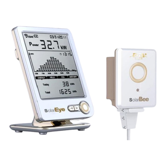
Solar Eye User Manual V1.0 1. Introductions Solar Eye is desktop monitoring device, developed for home and small commercial PV solar system. This device is able to monitor up to 5 inverters simultaneously, transfer data through wireless network and display relevant data on the LCD. -
Page 4: Safety And Notes
3)If the product is damaged, please contact your local maintenance center or return to the dealers/distributors for repair 4)Please do NOT try to open the Solar Eye and Solar Bee, or force it in anyway as it will VOID your warranty and we will not be able to exchange it 5)Please do not put Solar Eye in the water or any other liquids. -
Page 5: Product Installation
Solar Eye User Manual V1.0 ranging from -20℃ to 50 ℃, and relative humidity ≤ 80% 11)When Solar Eye is not in use for a long time, please remove the battery or cut off the power. 2. Product Installation The installation process includes the installation of Solar Bee and Solar Eye. - Page 6 Solar Eye User Manual V1.0 2.2 Solar Bee Wall Attach Installation 1) Use the ST2.7*6 screws to fix two suspension loops onto the pillars of Solar Bee. Fig 2-3 as below Fig 2-3 Suspension loop installation 2) Drill twoφ6 holes on the wall with 39mm space distance as Fig 2-4 Fig 2-4 Drill the wall mounting holes Attention: Hold the handgrip tightly;...
- Page 7 Solar Eye User Manual V1.0 Fig 2-5 Fix screws 5) Hang the Solar Bee on the screws fixed to the wall. Tighten the screw with a screwdriver slightly. Fig 2-6 as below Fig2-6 Install Solar Bee 6) Connect Solar Bee and the PV inverter together with the straight networking cable.
- Page 8 V1.0 2.3 SD Card (Optional) in Solar Eye and Battery Installation Solar Eye adopts SD card (compatible up to 4GB). Users is able to upgrade Solar Eye Firmware through SD card. 1)Open the battery cover of Solar Eye. Fig 2-8 as below Fig 2-8 Open battery cover 2)Put SD card into the slot, then lock the MICRO SD card clamping plate.
-
Page 9: Solar Eye Installation
2.4.1 Detachable Chassis Fixation Press the Solar Eye bottom groove into the convex of base. With a sound of clattering, installation will be finished. Fig 2-11 as below: Fig 2-11 Solar Eye base setting If want to remove Solar Eye from the base, press the base button and release connection. -
Page 10: Wall Mounting
Solar Eye User Manual V1.0 Fig2-12 Remove Solar Eye from base Warning: When remove the base, there should be no force in case of mechanical damage. 2.4.2 Wall Mounting 1)Drill two φ6 holes with 43mm space distance. Fig 2-13 as below:... - Page 11 Solar Eye User Manual V1.0 space outside. Fig 2-14 as below: Fig 2-14 Fix screws 4)Hook the Solar Eye over the two screw nails. Fig 2-15 as below: Fig 2-15 Hook Solar Eye on the wall Page 11 of 24...
-
Page 12: Interface Introduction
Solar Eye User Manual V1.0 3. Interface Introduction 3.1 Main Interface Solar Eye main interface as Fig 3-1: Fig 3-1 Solar Eye main interface Pos. Fig 3-1 Description Date Time Power trend Sub menu Gross generation Intraday generation Current generated power... - Page 13 Solar Eye User Manual V1.0 1)ENERGY interface:display E-today & E-total as Fig 3-2 Fig 3-2 ENERGY Interface 2)YIELD interface:display E-today yield & E-total yield as Fig 3-3 Fig 3-3 YIELD Interface 3)CO2 interface:display CO2 emission volume today and in total as Fig3-4 Fig 3-4 CO2 Interface 4)HISTORY interface:display hourly, daily, weekly, monthly and yearly...
-
Page 14: Set & Operation
Solar Eye User Manual V1.0 Fig 3-5 HISTORY Interface 4. Set & Operation Three keys “left” ( C ), “right” ( B ), and “enter” ( A ) are available as Fig 4-1, which can help achieve all functions. Fig 4-1 Key Guide 4.1 Initial Setting... -
Page 15: Set Currency
Solar Eye User Manual V1.0 Fig 4-2 Set Time 4.1.2 Set Currency Currency setting interface is as Fig 4-3. Press “left” & “right” key to switch among “€、£ 、$、¥” and then choose the target one by “enter” key. When it’s finished, press “right” key to enter into yield coefficient setting interface. -
Page 16: Set Emission Coefficient
Fig 4-5 Set Emission Coefficient 4.2 Wireless Connection Solar Eye can be connected to EverSolar inverter (up to 5 inverters) as the following two ways. 4.2.1 Connection Type Type 1:One Solar Eye connects to multiple Solar Bee as Fig 4-6. -
Page 17: Set Up Wireless Connection
Solar Bee flashes, which indicates Solar Bee has been into connection state. 2) Hold “right” key of Solar Eye to go into connection state as Fig 4-8. At this time, the channel Solar Bee stays in will show on top left corner on Solar Eye, and press “left”... -
Page 18: Alarm Warning Setting
Eye goes back to the main menu automatically after 1 minute. 4) Please repeat operation process above again if the connection failure, One Solar Eye connects to several Solar Bee (up to 10); avoid to setting to same communication cannel. -
Page 19: Data Storage Interval Time Setting
Solar Eye User Manual V1.0 Setting alarm “on”, solar-eye alarm warning every 5 minutes to note user when inverter error happens. 4.4 Data Storage Interval Time Setting Data storage interval means the frequency of writing data to SD card. In the main menu, press and hold “left”... -
Page 20: History Energy And Power Value Yield View
Solar Eye User Manual V1.0 4.6 History Energy and Power Value Yield View Call up HISTORY menu, you press “right” button to view history data by switching the unit of Y axis among “Hour”“Day”“Week”“Month” and “Year” by pressing “right” button. Operation process show as below: 1)Hour:Press “right”... -
Page 21: Reference
Solar Eye User Manual V1.0 5. Reference: Table 5-1 Solar Eye specifications table Item Specifications Power supply DC 4.5V/100mA or AA*3 batteries Wireless communication range 100m Maxim MicroSD capacity support 4GByte -10~50℃ Operating temperature range ≤80% Operating humidity range Wireless Operating frequency... -
Page 22: Error Message
Solar Eye User Manual V1.0 6. Error Message Table 6-1 Error Message Error Single phase error message Three phases error message Code GFCI Failure GFCI Failure AC HCT Failure AC HCT Failure Reference Voltage Fault DC inj. differs for M-S DC inj. - Page 23 Solar Eye User Manual V1.0 Communication Fails SPI Failure: Communication between M-S Fails between M-S SPI Failure: Communication Fails between M-S EEPROM R/W Fail Relay check Fail DC Injection High The result of Auto Test unction is fail DC bus is too high...
Need help?
Do you have a question about the Solar Eye and is the answer not in the manual?
Questions and answers