
Summary of Contents for Rock Hound 72B
- Page 1 Models: 60B & 72B Operation & Maintenance Manual ROCKHOUND ATTACHMENTS 2507 Tully Road Hughson, CA 95326 Phone: 1-800-426-5615 Fax: (360) 230-2322 6724506 (5-03) Revised (4-19) Printed in U.S.A.
-
Page 3: Table Of Contents
CONTENTS FOREWORD FOREWORD ............SAFETY . - Page 4 Rockhound Operation & Maintenance Manual...
-
Page 5: Foreword
FOREWORD FOREWORD This Operation & Maintenance Manual was written to give the owner/operator instructions on the safe operation and maintenance of the Rockhound. READ AND UNDERSTAND THIS OPERATION & MAINTENANCE MANUAL BEFORE OPERATING YOUR ROCKHOUND. If you have any questions, see your Rockhound dealer. - Page 7 SERIAL NUMBER LOCATION It is important to make the correct reference to the serial number of the Rockhound when making repairs or ordering parts. Early or later models (identifications made by serial number) may use different parts, or it may be necessary to use different procedures in doing a specific service operation.
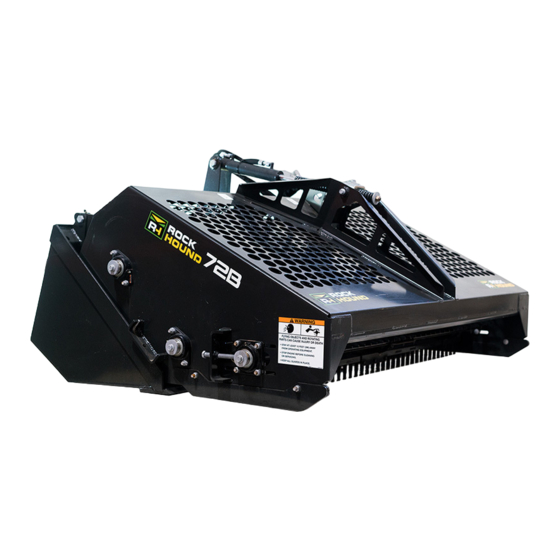
- Page 8 ROCKHOUND PARTS IDENTIFICATION AND MACHINE SIGNS (DECALS) CYLINDER MOTOR 6533898 (2) 6595014 (2) DRIVE MOTOR GUARD RAKE CHAIN & TEETH ADJUSTMENT BOLT 6711402 6594488 6701391 PORT 6708061 BLOCK 6708822 (2) BEARINGS PROP 65 STEPS P- -09637 P- -09638 Rockhound Operation & Maintenance Manual...
-
Page 9: Safety
SAFETY SAFETY INSTRUCTIONS ......... . SAFETY Rockhound Operation &... - Page 10 Rockhound viii Operation & Maintenance Manual...
- Page 11 SAFETY INSTRUCTIONS SAFETY IS THE OPERATOR’S RESPONSIBILITY A QUALIFIED OPERATOR* MUST DO THE FOLLOWING: *For an operator to be qualified, he must not use drugs or alcoholic drinks which impair his alertness or coordination while working. An operator who is taking prescription drugs must get medical advice to determine if he can safely operate a machine.
- Page 12 PROPOSITION 65 WARNING • California's Proposition 65 entitles California consumers to special warnings for products that contain chemicals known to the state of California to cause cancer if those products expose consumers to such chemicals above certain threshold levels.
-
Page 13: Operating Instructions
OPERATING INSTRUCTIONS MOUNTING THE ROCKHOUND -- 3--POINT HITCH (CATEGORY 1) EQUIPPED ......Closed Center Hydraulic System ........Hydraulic Installation . - Page 15 READ ALL MACHINE SIGNS (DECALS) AND INSTRUCTIONS CAREFULLY SETTING UP (BEFORE FIRST OPERATION) The Rockhound is delivered completely assembled. Supply hoses and couplers must be ordered separately. Check all nuts and bolts for correct torque. Check for shipping damage. If damaged, do not use the attachment until parts have been replaced or repaired.
- Page 16 OPERATING THE ROCKHOUND (SKID STEER LOADERS) (Cont’d) Recommended Raking Procedure (Cont’d) Use the tilt control cylinder to tilt the Rockhound up or down as needed during raking. NOTE: Soil conditions may require multiple passes. NOTE: Refer to your machines Operation &...
-
Page 17: Mounting The Rockhound
MOUNTING THE ROCKHOUND - - 3- -Point Hitch (Category 1) Equipped Drive the tractor backwards to the Rockhound Attachment equipped with the 3--Point Hitch mounting bracket. Align the two lower links of the 3--Point Hitch with the lower link mounts (Item 1) [A] on the mounting bracket. Install a pin (Item 2) [A] in each lower link and link mounting bracket to fasten the 3--Point Hitch links to the Rockhound. -
Page 18: Closed Center Hydraulic System
MOUNTING THE ROCKHOUND - - 3- -Point Hitch (Category 1) Equipped (Cont’d) Hydraulic Installation Two auxiliary hydraulic controls are needed for installation using a 3--Point Hitch. One auxiliary drives the hydraulic motor and the rake chain; the other auxiliary is connected to the top link cylinder at the upper mount and is used for dumping the bucket. -
Page 19: Open Center Hydraulic System
MOUNTING THE ROCKHOUND - - 3- -Point Hitch (Category 1) Equipped (Cont’d) Open Center Hydraulic System An open center system allows pressurized flow through the loader control valve. In this type of system the rockhound control valve is pressurized from the power beyond port of the tractor control valve (Item 1) [A]. -
Page 20: Operating The Rockhound
OPERATING THE ROCKHOUND - - 3- -Point Hitch (Category 1) Equipped Ground Preparation Thoroughly inspect the ground before raking. Remove large branches and stones which are 6 inches (150 mm) or larger. Checking Rockhound Operation See your tractor Operation & Maintenance Manual for safe operating procedures for your tractor/loader. -
Page 21: Dumping The Bucket
OPERATING THE ROCKHOUND - - 3- -Point Hitch (Category 1) Equipped (Cont’d) Operating the Rockhound See your Tractor Operation & Maintenance Manual for safe operating procedures for your tractor/loader. Raise the rake off the ground and drive to the starting point. - Page 22 OPERATING THE ROCKHOUND - - 3- -Point Hitch (Category 1) Equipped (Cont’d) Bucket Dump Adjustment Start the tractor engine and raise the 3--Point Hitch all the way [A]. Extend the top link cylinder to dump the bucket. When the rake cylinder (Item 1) [A] is fully retracted the bucket will open.
-
Page 23: Transporting The Rockhound
TRANSPORTING THE ROCKHOUND Lifting The Rockhound NOTE: Use chains that are in good condition and of adequate size to lift or secure the attachment. Hook each end of the chain (Item 1) [A] to the lifting slots in the Rockhound frame. P- -09642 Chaining The Rockhound Onto The Transport Vehicle... -
Page 24: Loading The Rockhound Onto The Transport Vehicle
TRANSPORTING THE ROCKHOUND (Cont’d) Rock Hound Operation & Maintenance Manual #6724506- - Operating Instructions Section Loading The Rockhound Onto The Transport Vehicle NOTE: Refer to your machines Operator’s Manual to correctly load and chain the machine and Rockhound onto the transport vehicle. -
Page 25: Rockhound Service
ROCKHOUND SERVICE DRIVE MOTOR ........... Drive Chain Adjustment . - Page 26 Rockhoun. d -14- Operatt. o n & Maintenance Manual...
- Page 27 AVOID INJURY OR DEATH Instructions are necessary before doing service on the Rockhound attachment. See warnings and instructions both at beginning and throughout this manual. After servicing, repairing or adjusting, always check for correct function of the Rockhound. SERVICE SCHEDULE Maintenance work must be done at regular intervals.
- Page 28 AVOID INJURY OR DEATH Before cleaning, servicing or repairing the Rockhound attachment: • Level and lower the attachment to the ground. • Stop the engine. • Release pressure in all hydraulic circuits. TROUBLESHOOTING Chart PROBLEM CAUSE CORRECTION Rockhound chain does not turn. Faulty drive motor.
- Page 29 ROCKHOUND LUBRICATION Lubricate the grease fittings on the Rockhound chain mounting bearings every 8 hours [A] & [B]. P- -09645 NOTE: The grease fitting on the drive sprocket bearing is located under the drive motor shield (Item 1) [B]. P- -09646 Lubricate the grease fittings (Item 1) [C] on the Rockhound hinges.
- Page 30 ROCKHOUND CYLINDER Removal and Installation NOTE: Be sure to fully extend the cylinder before stopping the loader engine. Exit the loader. Disconnect the hydraulic hoses (Item 1) [A] from the cylinder. Remove the mounting nut (Item 2) [A] and bolt from the cylinder base end mounting bracket.
- Page 31 ROCKHOUND CYLINDER (Cont’d) Cylinder Rod Guide Removal and Installation (Cont’d) NOTE: The rod wipers can be removed from the guide while on the Rockhound. The guide is removed from the Rockhound for clarity. Remove the rod wipers (Item 1) [A] from the guide. N- -00322 When installing the rod wipers, the lip must be toward the outside of the guide [B].
- Page 32 DRIVE MOTOR Drive Chain Adjustment Remove the four bolts (Item 1) [A] from the motor shield. P- -09647 Loosen the idle sprocket bolt (Item 1) [B] and move the idle sprocket to adjust the chain tension to be 1/2 inch (12,7 mm) deflection in the middle of the chain.
- Page 33 DRIVE MOTOR (Cont’d) Drive Chain Removal and Installation (Cont’d) Remove the retainer [A]. N- -00312 Separate the drive chain and the link [B]. Remove the drive chain from the sprockets. N- -00313 Drive Motor Removal and Installation Remove the drive motor shield. (See Page 20.) Remove the drive chain.
- Page 34 DRIVE MOTOR (Cont’d) Drive Motor Removal and Installation (Cont’d) Remove the drive sprocket (Item 1) [A] from the motor shaft. Installation: Use anti--seize on the drive motor shaft during sprocket installation. N- -00314 Remove the key (Item 1) [B] from the drive motor shaft. Remove the two nuts (Item 2) [B] from the motor mounting bolts.
- Page 35 PORT BLOCK Relief Valve Removal and Installation The relief valve (Item 1) [A] is located on top of the port block. NOTE: See your dealer for the correct supply hoses and fittings. P- -09648 Removal and Installation Mark the hoses on the port block for correct location during assembly [B].
- Page 36 PORT BLOCK (Cont’d) Check Valve Removal and Installation NOTE: The port block contains an internal check valve and a 0.070 inch (1,8 mm) orifice to control the action of the Rockhound cylinder. Remove the fitting (Item 1) [A] to access the check valve. N- -00305 Remove the check valve (Item 1) [B] and replace if damaged.
- Page 37 HINGES Removal and Installation Remove the nuts (Item 1) [A] from the hinge bolts (both hinges). N- -00325 Remove the hinge bolts (both hinges) [B]. N- -00328 Remove the hinge(s) from the frame [C]. N- -00326 Remove the bushings (Item 1) [D] from the hinges. Assembly: Apply grease to all surfaces of the bushings during assembly.
- Page 38 ROCKHOUND BEARINGS Removal and Installation NOTE: The bearing removal procedure, from the bearing housings, is the same for all bearings. Loosen the nuts (Item 1) [A] and back the adjustment bolt (Item 2) [A] to release the tension on the Rockhound chain.
- Page 39 ROCKHOUND BEARINGS (Cont’d) Removal and Installation (Cont’d) Remove the nuts (Item 1) [A] from the bearing housing bolts. Remove the bearing housing from the frame. Remove the bearing from the housing. (See Page 26.) N- -00347 To remove the bearing from the drive shaft, the drive sprocket must first be removed.
- Page 40 ROCKHOUND CHAIN Removal and Installation NOTE: The chain removal procedure was done using an over head hoist and the Rockhound positioned upside down. Remove the shield from the drive motor. (See Page 20.) Remove the drive motor chain. (See Page 20.) Remove the hydraulic hoses from the motor.
- Page 41 ROCKHOUND CHAIN (Cont’d) Removal and Installation (Cont’d) Remove the cotter pin (Item 1) [A] from the retainer. Removed the retainer (Item 2) [A] from the three master links. N- -00318 Remove the link (Item 1) [B] from the three chain connectors.
- Page 42 ROCKHOUND CHAIN (Cont’d) Rock Hound Operation & Maintenance Manual #6724506- - Rockhound Service Section Removal and Installation (Cont’d) Remove the bearings from the shafts. (See Page 26.) Remove the shafts from the frame [A]. N- -00355 Remove the Rockhound chain from the Rockhound frame [B].
-
Page 43: Specifications
SPECIFICATIONS ROCKHOUND SPECIFICATIONS ........SPECIFICATION Rockhound - -31- - Operation &... - Page 44 R. o ckhound Operatiom & Mainten. a nce Manual -32-...
- Page 45 ROCKHOUND SPECIFICATIONS Total Weight ......1010 lbs. (485 kg) 1130 lbs. (512 kg). Bucket Capacity .
- Page 46 Rockhound Operation & Maintenance Manual -34-...
- Page 47 HYDRAULIC MOTOR Disassembly and Assembly When making repairs on hydrostatic and hydraulic systems, clean the work area before disassembly and keep all parts clean. Always use caps and plugs on hoses, tubelines and port to keep dirt out. Dirt can quickly damage B- -9215 the system.
- Page 48 HYDRAULIC MOTOR (Cont’d) - - Landscape Rake and Angle Broom Disassembly and Assembly (Cont’d) Remove the inner seal from the balance plate [A]. Balance Outer Outer Plate Installation: Put grease on the inner seal and install as Seal Seal shown [A]. B- -3046 Inner Seal B- -8733...
- Page 49 HYDRAULIC MOTOR (Cont’d) - - Landscape Rake and Angle Broom Disassembly and Assembly (Cont’d) Remove the valve drive [A]. B- -6377 Remove the geroler [B]. NOTE: All rollers must be installed in their original location. B- -6376 Remove the drive shaft [C]. B- -9239 Remove the wear plate [D].
- Page 50 HYDRAULIC MOTOR (Cont’d) - - Landscape Rake and Angle Broom Disassembly and Assembly (Cont’d) Remove the shaft face seal from the wear plate [A]. B- -6396 Remove the shaft and bearing assembly from the housing [B]. NOTE: The shaft and bearing assembly are not sold as individual parts.
- Page 51 HYDRAULIC MOTOR (Cont’d) - - Landscape Rake and Angle Broom Inspection Before the motor is assembled, check the following items: Clean all parts in clean solvent and use air pressure to dry them. Do not use cloth or paper because small pieces of material can get into the system and cause damage.
- Page 52 HYDRAULIC MOTOR (Cont’d) - - Landscape Rake and Rotate Valve Clockwise Angle Broom 1/2 Tooth to Engage Spline Timing the Hydraulic Motor The timing of the motor controls the direction of rotation Any One of 6 Ports of the drive shaft. The timing parts are as follows [A]. Open to Outside of Valve 1.
- Page 53 HYDRAULIC MOTOR (Cont’d) - - Landscape Rake and Angle Broom Rock Hound Operation & Maintenance Manual #6724506- - Specifications Section Flow Divider Disassembly and Assembly. Remove the port block mounting bolts [A]. Installation: Tighten the bolts to 200 in--lbs. (23 Nm) torque.
- Page 54 ROCKHOUND ATTACHMENTS limited warranty covers the replacement of defective parts F.O.B., Chicago, At which they are available. The warranty also provides labor allowance of $25.00 per hour to the dealer for warranty work on your machine. IT DOES NOT COVER Freight costs for the parts from our warehouse to your dealer.
- Page 55 CUSTOMER LIMITED WARRANTY RECORD CARD ROCKHOUND ATTACHMENTS warrants this machine to be free from defects in material or workmanship For a period of six (6) calendar months from the date if delivery to first registered owner, providing that The machine has not been altered or tampered with or been subject to negligent handling, accident, misuse or abuse.
Need help?
Do you have a question about the 72B and is the answer not in the manual?
Questions and answers