Advertisement
Quick Links
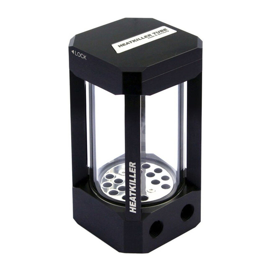
HEATKILLER® Tube Serie
Montageanleitung /
1
Assembly Instructions
1. Einleitung
Vielen Dank das Sie sich für ein Produkt aus
dem Hause Watercool entschieden haben.
Die HEATKILLER® TUBE Serie ist vollständig
modular aufgebaut. Das heißt das einzelne
Teile nachträglich getauscht werden können.
Zum Beispiel kann ein Unterteil für eine DDC
Pumpe gegen ein Unterteil für eine D5 Pumpe
getauscht werden.
Bitte lesen Sie sich diese Anleitung
sorgfältig durch. Die Firma Watercool e.K.
übernimmt keinerlei Haftung für Schäden,
welche
durch
Handhabung entstehen..
eine
unsachgemäße
1. Introduction
Thank you for choosing a Watercool product.
The HEATKILLER® TUBE Series is completely
modular. That means each part can be
exchanged separately. For example the base
for a DDC pump can be changed to a D5
pump compatible base.
Please read this manual with care. The
company Watercool e.K. is not liable for any
damage resulting from improper use.
Advertisement

Summary of Contents for Watercool HEATKILLER TUBE Series
- Page 1 Pumpe gegen ein Unterteil für eine D5 Pumpe getauscht werden. Please read this manual with care. The Bitte lesen Sie sich diese Anleitung company Watercool e.K. is not liable for any sorgfältig durch. Die Firma Watercool e.K. damage resulting from improper use. übernimmt keinerlei Haftung für Schäden,...
- Page 2 2. Öffnen und Schließen des 2. Opening and closing the lid Deckels (große Einfüllöffnung) (large filling mouth) Der Deckel kann durch eine Vierteldrehung The lid opens with a quarter turn in counter des Oberteils entgegen des Uhrzeigersinns clockwise direction. geöffnet werden. Abbildung /figure 1 3.
- Page 3 3.1 Die Pumpe vorbereiten 3.1 Preparing the pump Entfernen Sie das Pumpengehäuse von Ihrer Remove the pump body of your DDC pump DDC Pumpe. Dazu müssen vier Torx- by removing four torx screws from the pump schrauben (T 20) im Pumpenboden entfernt base.
- Page 4 3.3 Mounting the DDC pump 3.3 Montage der DDC Pumpe (sold (optional separately) erhältlich) Set the DDC pump motor (including the rotor) Setzen Sie den DDC Pumpenmotor (inklusive into the just removed pump cover. The cable Rotor) soeben abgeschraubte can be guided out through the small lateral Pumpenabdeckung.
- Page 5 4.3 Montage der D5 Pumpe 4.3 Mounting the D5 pump (optional (sold erhältlich) separately) Drehen zuerst leeren First turn the empty reservoir on its top side. Ausgleichbehälter auf den Kopf. Danach wird Then, the O-ring is put in place. Before der O-Ring eingelegt.
- Page 6 5. Zerlegen des 5. Disassembling the reservoir Ausgleichsbehälters To change for example the struts, the reservoir must be disassembled. This must be done in Um z.B. die Streben austauschen zu können the following order. muss der Ausgleichbehälter komplett zerlegt werden. Dies wird folgenden...
- Page 7 the O-rings are set in place correctly and are Achten Sie beim Einsetzen der Röhre not damaged. darauf dass die O-Ringe korrekt sitzen und nicht beschädigt werden. 5.5 Instructions for replacing the 5.5 Hinweise zum Austausch der O- O-rings Ringe To compensate the length tolerance of the Um die Längentoleranzen der Glasröhren glass tubes, we use different strength O-rings...
- Page 8 Abbildung/fure 4 7.1 Stand 7.1 Standfuß The pedestal is available in two sizes. Both are Der Standfuß ist in zwei Längen erhältlich. attached to the reservoir with two countersunk Beide werden über je zwei Senkschrauben am screws. Ausgleichsbehälter befestigt. With four holes in the bottom, the pedestal can Über vier Bohrungen im Fuß...
- Page 9 Abbildung/figure 5 radiator is also available. zur Montage an Radiatoren der MO-RA3 Serie ist ebenfalls erhältlich. 7.2.1 Die Halterung am 7.2.1 Fixing the mount to the Ausgleichbehälter befestigen reservoir Um die Klemmhalterung am Ausgleichbehälter To attach the bracket mount to the reservoir, zu montieren muss zuerst das Oberteil wie in first remove the top lid as described in 5.1.
- Page 10 7.2.2 direkte Montage 7.2.2 Direct mounting direkten Montage eine ebene The two inner M4 threads can be used to Oberfläche können die beiden inneren M4 mount the reservoir directly to a flat surface. A Gewinde der Halterung verwendet werden. decoupling unit can be used instead. Alternativ kann auch...
- Page 11 Abbildung/figure 5 worden, so darf der Ausgleichbehälter nicht in O-rings. Betrieb genommen werden. Wenden Sie sich Prior to all alterations to the reservoir it should bitte für einen neuen O-Ring an den Support. be drained and taken out of the water cooling Vor allen Umbauten am Ausgleichbehälter loop completely.
- Page 12 9. Zubehör / Accesoires 30230 HEATKILLER® Tube - Stand (short) 30231 HEATKILLER® Tube - Stand (long) 30232 HEATKILLER® Tube - Decoupling Kit for Stand 30233 HEATKILLER® Tube - 120mm Fan Adapter (pair) 30234 HEATKILLER® Tube - 140mm Fan Adapter (pair) 30235 HEATKILLER®...
Need help?
Do you have a question about the HEATKILLER TUBE Series and is the answer not in the manual?
Questions and answers