
Subscribe to Our Youtube Channel
Related Manuals for Generac Mobile MFH900

Summary of Contents for Generac Mobile MFH900
- Page 1 MFH900 Flameless Air Heater Owner’s Manual For technical assistance contact: www.generacmobileproducts.com Technical Support 1-800-926-9768 SAVE THIS MANUAL FOR FUTURE REFERENCE...
- Page 2 Engine and generator serial numbers are located on data Unit Serial No. plates affixed to the engine and generator, respectively. When contacting a Generac Mobile Authorized Service Engine Model No. Dealer (GMASD) about parts and service, always provide the unit model and serial number.
-
Page 3: Table Of Contents
Table of Contents Section 1: Introduction and Safety Section 3: Operation Introduction ..............1 Before Starting Engine ..........21 Read This Manual Thoroughly ........1 Pre-start Checklist .............21 Safety Rules ..............1 Engine Oil Check ............21 How to Obtain Service ..........1 Hydraulic Oil Check ...........21 General Hazards ............2 Engine Coolant Check ..........21 Explosion and Fire Hazards ........2... - Page 4 This page intentionally left blank. Owner’s Manual for Flameless Air Heater...
-
Page 5: Section 1: Introduction And Safety
DANGER, WARNING, CAUTION, and maintained properly. NOTE blocks are used to alert personnel to special The MFH900 flameless air heater is designed and built instructions about a particular operation that may be haz- for sustained, reliable heat production in industrial oper- ardous if performed incorrectly or carelessly. -
Page 6: General Hazards
Introduction and Safety General Hazards CAUTION DANGER Equipment Damage. The emergency stop switch is not to be used to power down the unit under normal Asphyxiation. Running engines produce operating circumstances. Doing so could result in carbon monoxide, a colorless, odorless, equipment damage. -
Page 7: Trailer Hazards
Introduction and Safety Trailer Hazards WARNING WARNING Accidental Start-up. Disconnect the negative battery cable, then the positive battery cable when working Personal injury. Trailer must be securely coupled to on unit. Failure to do so could result in death the hitch with the chains correctly attached. Uncoupled or serious injury. -
Page 8: Hitch And Coupling
If you believe your trailer has a defect which could cause a crash, injury, or death, you should immediately inform the National Highway Traffic Safety Administration (NHTSA) in addition to notifying Generac Mobile Prod- ucts, LLC. If NHTSA receives similar complaints, it may open an investigation. -
Page 9: Section 2: General Information
Section 2: General Information Specifications Description Unit of Measure MFH900 Engine Make (Model) — Perkins (1204F-E44TTA) EPA Certification tier 4 Final Type — Diesel, liquid cooled, 4-stroke Horsepower At Operating Speed hp (kW) 150 (112 kW) Operating Speed 2,200 Displacement 268.5 (4.4) -
Page 10: Unit Dimensions
Ins. Class FOR ELECTRICAL EQUIPMENT ONLY. POUR MATERIAL ELECTRIQUE SEULEMENT. 209649 Form: SFC626B VIN Tag TIRE AND LOADING INFORMATION MANUFACTURED BY/FABRIQUE PAR: Generac Mobile Products LLC DATE: 00/0000 GVWR/PNBV: 000KG (0000LBS) COLD INF. PRESS./ RENSEIGNEMENTS SUR LES PRESS. DE PNEUS ET LE CHARGEMENT... -
Page 11: Component Locations
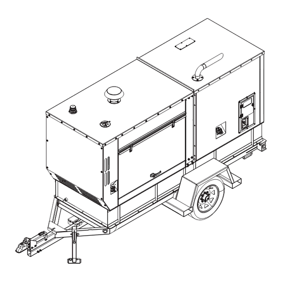
General Information Component Locations Exterior Figure 2-3. Exterior Components Roof beacon Fuel fill Radiator fill access panel Tie-down (4 locations) Air intake Forklift pocket (4 locations) Exhaust DEF fill Control panel Battery for breakaway brakes Emergency stop switch Union fluid drain port M Hot air discharge ducts Owner’s Manual for Flameless Air Heater... -
Page 12: Interior
General Information Interior 000000 Figure 2-4. Interior Components—1 of 2 A Engine crankcase filter HTF ball valve B Secondary fuel filter M Engine oil level gauge (dipstick) C Primary fuel filter (water separator) N Engine oil filter D Fuel lift pump O Engine oil ball valve E Heat transfer fluid (HTF or hydraulic fluid) P Engine oil fill... - Page 13 General Information 000000 Figure 2-5. Interior Components—2 of 2 Selective catalytic reduction (SCR) canister Engine starter Intake air filter Ground strip (on floor) Engine radiator Fuse block (next to ground strip) Union drain manifold (through hole in floor)—ball Battery disconnect switch valves for DEF, coolant, and fuel Positive air shutdown (PAS) Hydraulic manifold (behind shield)
-
Page 14: Control Panel
General Information Control Panel Figure 2-6. Control Panel Controller Unit start switch Main power switch Light switch Emergency stop switch USB port Owner’s Manual for Flameless Air Heater... -
Page 15: Controller
General Information Controller Figure 2-7. MFH900 Controller—Common Functions Main button (eight) Eight buttons around the screen are for page-to-page navigation or real-time heater adjustment. Figure 2-8. On most pages, an icon displays next to each button (A). Each icon indicates what navigation or adjustment occurs when the corresponding button is pushed. -
Page 16: Controller Display: Alert (Icon) Definitions
General Information Controller Display: Alert (Icon) Definitions Figure 2-9. The controller displays many alerts in specific areas of the controller (A). Alerts are often accompanied by explanatory text (B). Figure 2-9. Alerts Display Some alerts are routine and indicate normal unit function; others indicate problems. -
Page 17: Controller Faceplate Icons
General Information Controller Faceplate Icons Figure 2-6, Four icons are stamped into the controller faceplate. They illuminate according to situation. Figure 2-10. Faceplate Icons Icon (Lit) Indicates Photo sensor for controller display (day or night mode) When lit (green), controller power is ON When lit, USB cable is connected [not used] Owner’s Manual for Flameless Air Heater... -
Page 18: Emissions Information
Use only ultra-low-sulfur diesel fuel. • 000000 When temperatures are at or below freezing, use • Figure 2-11. MFH900 Engine Oil Viscosity No. 1D diesel fuel. When temperatures are above freezing, use No. • NOTE: For temperatures below -4 °F (-20 °C), use SAE 2D diesel fuel. -
Page 19: Hydraulic Oil
General Information Hydraulic Oil 6. Trailer and doors are secured and latched. DANGER Wheel Chock Guidelines Hydraulic Fluid Injection. High-pressure, high-temperature WARNING hydraulic fluid can pierce skin and cause severe burns. Do not check for leaks with hands. Seek immediate medical attention in case of accident. -
Page 20: Controller Mode
Figure 2-15. Password Entry Page Access Engine & Fuel Information page Change mode 2. Enter the password. Increase air-output temperature IMPORTANT NOTE: Contact Generac Mobile Techni- Decrease air-output temperature cal Service for password. Access Engine Diagnostics page About AUTO Mode Accessing Home Page from Other Pages In AUTO Mode, three temperatures are available. -
Page 21: Controller Monitoring, Diagnostic, And Protective Features
General Information Controller Monitoring, Diagnostic, and MANUAL Mode Navigation Protective Features Mechanical and electrical systems are connected to vari- ous sensors that monitor unit status. If conditions occur outside of predetermined manufacturing parameters, the controller will automatically stop the machine and display fault information. - Page 22 General Information 4. See Figure 2-21. The Password Entry page dis- Figure 2-23. The Enter Password page displays. plays. Enter the password. Figure 2-23. Enter Password Page Figure 2-21. Password Entry Page 5. Enter the password. NOTE: To enter password: Twist knob to scroll through Figure 2-24.
-
Page 23: Advanced Controller Functions
General Information Advanced Controller Functions Figure 2-30. Page 2 displays. Advanced controller functions are only available in MANUAL mode. A password is required. To access an advanced controller function: 1. Change controller mode to MANUAL. See Con- troller Mode. Figure 2-27. -
Page 24: Owner's Manual For Flameless Air Heater
General Information This page intentionally left blank. Owner’s Manual for Flameless Air Heater... -
Page 25: Section 3: Operation
Section 3: Operation Before Starting Engine Hydraulic Oil Check On the hydraulic fluid reservoir tank is a gauge showing hydraulic oil level. Verify level is between MIN and MAX. Pre-start Checklist WARNING Engine Coolant Check Hot Surfaces. When operating machine, do not WARNING touch hot surfaces. -
Page 26: Starting Engine And Heater
Operation Starting Engine and Heater Adjusting Air Output Temperature This section applies both to MANUAL and AUTO modes. This section applies both to MANUAL and AUTO modes. 1. Verify unit is fully operational—controller must NOTE: The unit starts in the mode in which it was last display Heater Run. -
Page 27: Changing Controller Mode
Operation Changing Controller Mode activated with doors closed locked. Figure 3-6. The Mode icon (A) displays on various pages. When it displays, change controller mode by pressing corresponding button once. 006235 003575b Figure 3-6. Mode Icon Figure 3-8. Emergency Stop Switch Shutting Down Engine and Heater 1. - Page 28 Operation This page intentionally left blank. Owner’s Manual for Flameless Air Heater...
-
Page 29: Section 4: Maintenance
Section 4: Maintenance NOTE: Normal maintenance, service, and replacement 2. Slowly insert the clean oil dipstick into the tube. of parts are the responsibility of the owner and are not Verify the oil dipstick is fully seated in the oil considered defects in materials or workmanship within dipstick tube. -
Page 30: Draining Fluids-Union Fluid Drain
Maintenance Draining Fluids—Union Fluid Drain To drain a fluid: IMPORTANT NOTE: Drain one fluid at a time. Figure 4-1. This unit is equipped with a union fluid drain (A), an exterior drain port for multiple fluids— WARNING engine oil, engine fuel, engine coolant, hydraulic oil, and DEF. -
Page 31: Removing Crankcase Filter
Maintenance 2. Remove radiator cap. 3. Fill radiator slowly with coolant until it comes up to the filler neck. 4. Operate engine approximately five minutes at a low idle speed to bleed the air in the coolant circuit. NOTE: Coolant level will drop. 5. -
Page 32: Maintenance Schedule
Maintenance Maintenance Schedule Periodic inspection, service, and maintenance of this unit Follow all applicable safety alerts found in this manual or is critical to ensure reliable operation. The following is the engine service manual before performing manufacturer’s recommended maintenance schedule. maintenance checks or service. -
Page 33: Hydraulic Oil Schedule
Maintenance Every 4,000 hr Clean/test aftercooler core • Every 4,500 hr or 3 yr Change DEF dosing unit filter • Every 6,000 hr or 3 yr Add coolant extender (ELC) • Every 10,000 hr Replace DEF manifold filters • Every 12,000 hr or 6 yr Change coolant (ELC) •... -
Page 34: Other Maintenance Checks
Maintenance Figure 4-5. The Service Hours Engine page displays. Figure 4-5. Service Hours Engine Page 3. On this page, you can: View service intervals. • View hours remaining until next scheduled • service. Press a RESET button to reset the •... -
Page 35: Section 5: Troubleshooting
Section 5: Troubleshooting General Troubleshooting Guide Problem Possible Cause Solution No fuel Verify there is no fuel leakage and replenish. Low oil level Replenish oil to full. Emergency shutdown Turn emergency shutdown switch OFF. switch is ON Air in fuel system Purge air. - Page 36 Troubleshooting Problem Possible Cause Solution Adjust by idling control equipment on the machine. If adjustment is not Low idle possible, contact ISUZU dealer. Clogged fuel filter Remove water and change element. Clogged pre-fuel filter Clean or change element. Clogged air cleaner Engine starts but stops shortly there- Engine control system...
- Page 37 Troubleshooting Problem Possible Cause Solution Clogged air cleaner Clean element. Clogged pre-fuel filter Clogged fuel filter Remove water and change element. Clogged strainer Engine control system failure Engine has no Engine failure power Clogged exhaust sys- Contact an IASD. Fuel system failure Incorrect fuel type Electromagnetic type fuel pump failure...
-
Page 38: Controller Warnings And Faults
The controller indicates warnings and faults by displaying messages in the message bar (A) and/or by displaying an icon (B, for example). Figure 5-1. NOTE: For more information on warnings and faults, contact Generac Mobile Technical Service at 1-800-926-9786. Icon Icon ID... - Page 39 Troubleshooting Hydraulic Oil Steady ON (amber) Tank >160 °F (71 °C) or oil stream >200 °F (93 °C) Temperature Steady ON (red) Tank >170 °F (77 °C) or oil stream >210 °F (99 °C) Steady ON High-temperature cut-out switch open Hydraulic Return Filter Filter condition Engine Overspeed...
- Page 40 Troubleshooting This page intentionally left blank. Owner’s Manual for Flameless Air Heater...
-
Page 41: Section 6: Wiring Diagrams
Section 6: Wiring Diagrams Main Control System Owner’s Manual for Flameless Air Heater... -
Page 42: Perkins Engine Aftertreatment
Wiring Diagrams Perkins Engine Aftertreatment GROUP G Owner’s Manual for Flameless Air Heater... -
Page 43: J1939 Can Bus Network
Wiring Diagrams J1939 CAN Bus Network GROUP G J1939 CANBUS NETWORK DIAGRAM Owner’s Manual for Flameless Air Heater... -
Page 44: Trailer Harness-Electric Brakes
Wiring Diagrams Trailer Harness—Electric Brakes GROUP G Owner’s Manual for Flameless Air Heater... -
Page 45: Trailer Harness-Lights Only Or With Surge Brakes
Wiring Diagrams Trailer Harness—Lights Only or With Surge Brakes GROUP G Owner’s Manual for Flameless Air Heater... - Page 46 Wiring Diagrams Owner’s Manual for Flameless Air Heater...
-
Page 47: Hydraulic Circuit
Wiring Diagrams Hydraulic Circuit '' FAN PRESSURE HOSE 3,000 PSI MAX VC10-2 VC10-2 HVC10-3 0-4000PSI HVC16-S3 VC08-2 TEMP '' RETURN HOSE 1 1/4'' PRESSURE HOSE 1,000 PSI MAX 5,000 PSI MAX '' FAN RETURN HOSE 3,000 PSI MAX #12 TO #16 TO #8 SAE #20 SAE... - Page 48 Wiring Diagrams This page intentionally left blank. Owner’s Manual for Flameless Air Heater...
- Page 49 Wiring Diagrams This page intentionally left blank. Owner’s Manual for Flameless Air Heater...
- Page 50 Wiring Diagrams This page intentionally left blank. Owner’s Manual for Flameless Air Heater...
- Page 52 ©2018 Generac Mobile Products, LLC All rights reserved. Generac Mobile Products, LLC Specifications are subject to change without notice. 215 Power Drive, Berlin, WI 54923 No reproduction allowed in any form without prior written GeneracMobileProducts.com │800-926-9768 │920-361-4442 consent from Generac Mobile Products, LLC.
Need help?
Do you have a question about the MFH900 and is the answer not in the manual?
Questions and answers