Table of Contents
Advertisement
DATE
11/7/2008
SUPERSEDES
N/A
ECO #
REVISION
Eng. Draft
Prepared by:____________________________
Approved by: ___________________________
Approved by: ___________________________
Approved by: ___________________________
Quality and Regulatory Affairs
Approved by: ___________________________
STANDARD PROCEDURE INSTRUCTIONS
COSMAN MEDICAL, INC
G4 Service Manual
DESCRIPTION
1
Version for initial product release.
Manufacturing
Engineering
Management
SPI #
11291
PAGE
DO NOT ISSUE REV
SHEET
Date: ____________
Date: ____________
Date: ____________
Date: ____________
Date: ____________
REV.
A
1
of
115
Advertisement
Table of Contents

Subscribe to Our Youtube Channel
Related Manuals for Cosman G4

Summary of Contents for Cosman G4
- Page 1 SPI # REV. 11/7/2008 STANDARD PROCEDURE INSTRUCTIONS 11291 SUPERSEDES PAGE COSMAN MEDICAL, INC DO NOT ISSUE REV SHEET G4 Service Manual ECO # REVISION DESCRIPTION Eng. Draft Version for initial product release. Prepared by:____________________________ Date: ____________ Approved by: ___________________________ Date: ____________...
- Page 2 Cosman G4 Radiofrequency Generator Service Manual (SPI Rev A) 11291 Section 1...
- Page 3 Cosman G4 Radiofrequency Generator Service Manual (SPI Rev A) 11291 Cosman G4 Radiofrequency Generator Service Manual Section 1...
- Page 4 Cosman Medical, Inc. warrants to the original purchaser that the equipment listed in the Operators’ Manual shall be free from defects in material and workmanship for a period of 1 year from the date of shipment. Cosman Medical, Inc. obligation under this warranty shall be limited to repair or replacement, at the option of Cosman Medical, Inc.
- Page 5 3.2 Indications for Use 16.15 Audio calibration adjustment 3.3 Unpacking the G4 System 16.16 Stimulator tests 4. Turning on the G4 & Main Menu 16.17 Maximum RF output test 5. System Setup 17. Electrical Safety Tests 5.1 Date, Time, Language, and Audio Volume 17.1 HIPOT Testing...
-
Page 6: General Information
1. General Information Safe and effective RF lesioning is dependent not only on equipment design, but also on factors under control of the operator. Do not attempt to operate the G4 prior to completely reading and understanding the instructions for use. -
Page 7: Electrical Safety Information
IEC 61000-4-2 (2001), 61000-4-3 (2006), 610004-4 (2004), 61000-4-5 (2005) 1.3 Electrical Safety Information The G4 is a radiofrequency generator designed to produce local tissue heating at the tip of an electrode by the presence of radio frequency current. Special isolation transformers are imposed between power lines and internal G4 circuitry, resulting in very low leakage current. - Page 8 WARNING: The use and proper placement of dispersive electrodes is a key element in the safe and effective use of this lesion generator, particularly in the prevention of burns. Read and follow Cosman’s dispersive electrode instructions for preparation, placement, surveillance, removal and use of any dispersive electrode.
- Page 9 NOTICE: Always record the wattage readings that correspond to a given temperature for a given technique. This gives extra guidance and helps Cosman Medical diagnose problems. WARNING: Proper electrode placement should be verified using anatomical...
- Page 10 Cosman G4 Radiofrequency Generator Service Manual (SPI Rev A) 11291 1.4 Key to Device Markings Mains Power Mains Power On Switch Main Power Off Switch Output Control Front-panel Start Button (Turn on electrode output) Front-panel Stop Button (Turn off electrode output)
- Page 11 Cosman G4 Radiofrequency Generator Service Manual (SPI Rev A) 11291 RF Electrode Output Connection 2 (on front panel) RF Electrode Output Connection 3 (on front panel) RF Electrode Output Connection 4 (on front panel) Other Connections Footswitch Remote Control Connection...
- Page 12 Cosman G4 Radiofrequency Generator Service Manual (SPI Rev A) 11291 Certifications Unit is compliant with the European Council Directive 93/42/EEC , Medical Device Directive Unit is approved by CSA to the US standard Warnings Warning: Consult Operator’s Manual. Warning: Dangerous Voltage. No user-serviceable parts inside.
- Page 13 Cosman G4 Radiofrequency Generator Service Manual (SPI Rev A) 11291 Other Type BF protection against electric shock. Floating or isolated applied part/defibrillator protected. Alternating current (AC) Screen Shot: Save image of screen to Procedure Record IPX0 Protection against ingression of water: Ordinary...
-
Page 14: Front Panel Layout
Cosman G4 Radiofrequency Generator Service Manual (SPI Rev A) 11291 2. Chassis Layout 2.1 Front Panel Layout Output On Indicator: Touch Screen Illuminated when any electrode output is on Front-panel Start Button: Turn on electrode output when the Stimulation (Sec. -
Page 15: Back Panel Layout
Cosman G4 Radiofrequency Generator Service Manual (SPI Rev A) 11291 2.2 Back Panel Layout USB Connection: A ttach printer or external USB disk. Fuse box and Mains AC Voltage Selection: • 100 Vac RFG-4 • 120 Vac • 220 Vac COSMAN MEDICAL , INC. -
Page 16: Getting Started
4. Turning on the G4 & Main Menu 1. After unpacking the G4 from the shipping box, plug the power cord into the rear of the unit. CAUTION: Make sure that the wall outlet voltage matches the voltage displayed on the Voltage Selector located on the rear of unit (100, 120, 220, or 240). - Page 17 Cosman G4 Radiofrequency Generator Service Manual (SPI Rev A) 11291 4. If the Time and Date is set, the Main Menu screen is displayed. If the Time and Date is not set, the System Setup screen is displayed and the Time and Date must be set (Section 5.1).
-
Page 18: System Setup
Cosman G4 Radiofrequency Generator Service Manual (SPI Rev A) 11291 5. System Setup 5.1 Date, Time, Language, and Audio Volume Main Menu Section 4 Press "Calibrate" Set Date (Month, Day, Year) Set Time (Hour, Minute, AM/PM) Change Language Change Audio... - Page 19 Cosman G4 Radiofrequency Generator Service Manual (SPI Rev A) 11291 5.2 Touch Screen Calibration 1. Carefully press and briefly hold the center of each cross-shaped target. Lift your finger or stylus from the screen and repeat when the target moves. Lift your finger from the screen when the target disappears.
- Page 20 Cosman G4 Radiofrequency Generator Service Manual (SPI Rev A) 11291 5.3 Testing the G4 Unit The ability of the generator to produce RF output and to measure Temperature and Impedance can be tested by attaching one or more Test Plugs (RFG-TP) to active electrode jacks and performing a procedure.
- Page 21 Cosman G4 Radiofrequency Generator Service Manual (SPI Rev A) 11291 5.4 Error and Warning Dialogs The generator will alert the user with a dialog box when error conditions occur or for other notification purposes. Display of an error dialog box is accompanied by an audible error tone, and the user is prompted...
- Page 22 Cosman G4 Radiofrequency Generator Service Manual (SPI Rev A) 11291 6. Start Procedure Screen Main Menu Section 4 Press "Start Procedure” on Selected Personal Main Menu Settings Preset screen Personal Settings Presets: The selected Preset will determine the initial Preset Summary:...
-
Page 23: Start Procedure
Cosman G4 Radiofrequency Generator Service Manual (SPI Rev A) 11291 7. Electrode Setup Screen Start Procedure Section 6 Disconnect electrodes and probe from any output connector shown on the screen Current Personal marked with a red “X”. Settings Preset Current Electrode Setup... - Page 24 Cosman G4 Radiofrequency Generator Service Manual (SPI Rev A) 11291 7.1 Electrode Setup Settings The Electrode Setup settings determine which electrode output connections (Section 2.1) are to be delivered Stimulation, Thermal RF, and/or Pulsed RF output. • RF Type: This setting determines the polarity of active electrode output connections.
- Page 25 Cosman G4 Radiofrequency Generator Service Manual (SPI Rev A) 11291 8. Graphing Interface The Graphing interface is one of two user interfaces available for operation of the generator in Stimulation, Thermal RF, and Pulsed RF modes. The other is One Touch interface (Section 9). Choice of user interface is primarily a matter of user preference, since almost all generator functions (including full automatic ramp and temperature control) are available in both interfaces.
- Page 26 Cosman G4 Radiofrequency Generator Service Manual (SPI Rev A) 11291 8.1 Stimulation Screen Personal Settings Preset Electrode Panel (Black area): Indicator Displays all readings for the Sensory Mode indicated electrode output. Electrode Setup Indicator Indicator (Section 7.1) Output Off Screen Shot Button:...
- Page 27 Cosman G4 Radiofrequency Generator Service Manual (SPI Rev A) 11291 8.1.1 Additional Example Screens The Graphing Stimulation screen will appear differently depending on the current settings: • Electrode Setup settings (see Section 7.1) • Stimulation Mode: Sensory or Motor •...
- Page 28 Cosman G4 Radiofrequency Generator Service Manual (SPI Rev A) 11291 8.1.2 Stimulation Settings The Electrode Setup settings (Section 7.1) determine the configuration of electrodes when the generator delivers Sensory and Motor Stimulation output. The "Electrode Select Buttons" on the Stimulation screen (see Section 8.1) are used to select one electrode at a time, or one bipolar electrode pair at a time, from...
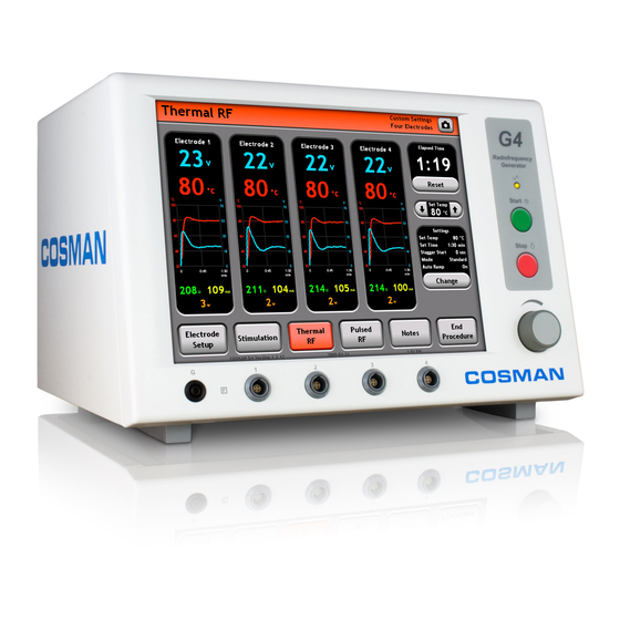
- Page 29 Cosman G4 Radiofrequency Generator Service Manual (SPI Rev A) 11291 8.2 Thermal RF Screen Personal Settings Preset Electrode Panel (Black area): Indicator Displays all readings for the indicated electrode output. When Electrode Setup Indicator enabled, RF output is delivered to (Section 7.1)
- Page 30 Cosman G4 Radiofrequency Generator Service Manual (SPI Rev A) 11291 8.2.1 Additional Example Screens The Graphing Thermal RF screen will appear differently depending on the current settings: • Electrode Setup settings (see Section 7.1) • Thermal RF Mode: Standard or Stepped (see Section 8.2.2) Timer: Cannot be reset in Stepped Mode.
- Page 31 Temperature-related errors. Auto Ramp is set to Off and the Thermal RF output Voltage must be controlled manually by the user with the Output Control Knob. Use this setting with electrodes that do not monitor temperature, e.g. Cosman CR Electrode.
- Page 32 Cosman G4 Radiofrequency Generator Service Manual (SPI Rev A) 11291 8.3 Pulsed RF Screen Personal Settings Preset Electrode Panel (Black area): Indicator Displays all readings for the indicated electrode output. When Electrode Setup Indicator enabled, RF output is delivered to (Section 7.1)
- Page 33 Cosman G4 Radiofrequency Generator Service Manual (SPI Rev A) 11291 8.3.1 Additional Example Screens The Graphing Pulsed RF screen will appear differently depending on the current settings: • Electrode Setup settings (see Section 7.1) • E-dose setting: Vary Voltage, Vary Width, or Vary Rate (see Section 8.3.2)
- Page 34 Cosman G4 Radiofrequency Generator Service Manual (SPI Rev A) 11291 8.3.2 Pulsed RF Settings The Electrode Setup settings (Section 7.1) determine the number and configuration of electrodes when the generator delivers Pulsed RF output. When Pulsed RF output is enabled by the user, it is delivered to all electrodes selected as “active”...
- Page 35 Cosman G4 Radiofrequency Generator Service Manual (SPI Rev A) 11291 Selected parameters of the Pulsed RF waveform are shown schematically in the illustration below. Set Time Voltage Time RF off puls 1/Pulse Rate Pulse Width burst The Pulsed RF Settings Screen is shown below.
- Page 36 Cosman G4 Radiofrequency Generator Service Manual (SPI Rev A) 11291 9. One Touch Interface The One Touch interface is one of two user interfaces available for operation of the generator in Stimulation, Thermal RF, and Pulsed RF modes. The other is Graphing interface (Section 8). Choice of user interface is primarily a matter of user preference, since almost all generator functions are available in both interfaces.
- Page 37 Cosman G4 Radiofrequency Generator Service Manual (SPI Rev A) 11291 9.1 Stimulation Screen Electrode Panel Sensory Mode Output Increment & Decrement Personal Settings (Black area): Displays Auto Ramp & Units Indicator Buttons: Increase & decrease Preset Indicator all readings for the...
- Page 38 Cosman G4 Radiofrequency Generator Service Manual (SPI Rev A) 11291 9.1.1 Additional Example Screens The One Touch Stimulation screen will appear differently depending on the current settings: • Electrode Setup settings (see Section 7.1) • Stimulation Mode: Sensory or Motor •...
- Page 39 Cosman G4 Radiofrequency Generator Service Manual (SPI Rev A) 11291 9.1.2 Stimulation Settings The Electrode Setup settings (Section 7.1) determine the configuration of electrodes when the generator delivers Sensory and Motor Stimulation output. The "Electrode Select Buttons" on the Stimulation screen (see Section 9.1) are used to select one electrode at a time, or one bipolar electrode pair at a time, from...
- Page 40 Cosman G4 Radiofrequency Generator Service Manual (SPI Rev A) 11291 9.2 Thermal RF Screen Personal Settings Preset Electrode Panel (Black area): Timer: Holds value from Indicator Displays all readings for the last instance of Thermal Electrode Setup Indicator indicated electrode output. When RF output.
- Page 41 Cosman G4 Radiofrequency Generator Service Manual (SPI Rev A) 11291 9.2.1 Additional Example Screens The One Touch Thermal RF screen will appear differently depending on the current settings: • Electrode Setup settings (see Section 7.1) • Thermal RF Mode: Standard or Stepped (see Section 9.2.2)
- Page 42 Temperature-related errors. Auto Ramp is set to Off and the Thermal RF output Voltage must be controlled manually by the user with the Output Control Knob. Use this setting with electrodes that do not monitor temperature, e.g. Cosman CR Electrode.
- Page 43 Cosman G4 Radiofrequency Generator Service Manual (SPI Rev A) 11291 Pulsed RF Screen Personal Settings Preset Electrode Panel (Black area): Timer: Holds value from Indicator Displays all readings for the last instance of Pulsed indicated electrode output. When RF output.
- Page 44 Cosman G4 Radiofrequency Generator Service Manual (SPI Rev A) 11291 9.2.3 Additional Example Screens The One Touch Pulsed RF screen will appear differently depending on the current settings: • Electrode Setup settings (see Section 7.1) • E-dose setting: Vary Voltage, Vary Width, or Vary Rate (see Section 9.2.4)
- Page 45 Cosman G4 Radiofrequency Generator Service Manual (SPI Rev A) 11291 9.2.4 Pulsed RF Settings The Electrode Setup settings (Section 7.1) determine the number and configuration of electrodes when the generator delivers Pulsed RF output. When Pulsed RF output is enabled by the user, it is delivered to all electrodes selected as “active”...
- Page 46 Cosman G4 Radiofrequency Generator Service Manual (SPI Rev A) 11291 Selected parameters of the Pulsed RF waveform are shown schematically in the illustration below. Set Time Voltage Time RF off puls 1/Pulse Rate Pulse Width burst An Example of a Pulsed RF Change Settings screen is shown below.
- Page 47 No other parts may be autoclaved. 10.1.2 Care The G4 may be cleaned by wiping with a soft cloth dampened with a mild detergent. Do not allow liquid to get into the unit. The cables and accessories may be wiped with mild detergent cleaning solutions, taking care to keep moisture out of the connectors.
- Page 48 Cosman G4 Radiofrequency Generator Service Manual (SPI Rev A) 11291 This page intentionally blank Section 10...
-
Page 49: Troubleshooting
Cosman G4 Radiofrequency Generator Service Manual (SPI Rev A) 11291 11. Troubleshooting Problem Possible Cause • Bad AC outlet Generator will not turn on by Mains Power switch • Defective power cord • Blown fuses • Button has no function in current No response when button is pressed operating mode, e.g. - Page 50 Cosman G4 Radiofrequency Generator Service Manual (SPI Rev A) 11291 Problem Possible Cause output shuts down prematurely • Temperature above 100 °C. • Break in electrode or electrode cables. May be intermittent problem. • Set Time setting too low • Maximum RF Current or Power limit exceeded •...
-
Page 51: Specifications
Cosman G4 Radiofrequency Generator Service Manual (SPI Rev A) 11291 12. Specifications ELECTRICAL SUPPLY Volts (mains switch unit) Volts input range Voltage Specifications: 100Vac 90-110 120Vac 105-125 220Vac 200-240 240Vac 220-260 Maximum input voltage: 260Vac Maximum voltage on any input connector:... - Page 52 Cosman G4 Radiofrequency Generator Service Manual (SPI Rev A) 11291 THERMAL & PULSED RF OUTPUT (continued) Volts: 0 to 70 volts RMS into 100Ω load during Thermal RF output. 0 to 100 volts peak into 100Ω during Pulsed RF output.
- Page 53 Cosman G4 Radiofrequency Generator Service Manual (SPI Rev A) 11291 13. Output Power Curves Output Power ver Knob Setting 50 ohms 100 ohms 200 ohms 500 ohms 1000 ohms 1500 ohms Knob Setting Output Power ver Resistance Half Full 1000...
- Page 54 Cosman G4 Radiofrequency Generator Service Manual (SPI Rev A) 11291 14. Accessories Cosman Medical Part No. Description CB112-TC Connecting Cable for TC Electrodes C119 Power Cord (120 Volts) C118 Power Cord (foreign style, 230 Volts) FUSE-2A 2.0 Amp Fuse (2)
-
Page 55: Test Equipment
Open circuit the signal should be smaller than 2.5v peak to peak. With a single 100 Ω load the signal should be smaller than 2v peak to peak. If the values differ substantially from those listed above the unit must be returned to Cosman Medical for evaluation and repair. - Page 56 Verify that both read within +/-3°C of each other Repeat for electrode output jacks 2 through 4 If the values differ substantially from those listed above the unit must be returned to Cosman Medical for evaluation and repair. 16.5 High volts measurement calibration Select Electrode Setup, 1 Active Electrodes, then Thermal RF, Auto Ramp off Attach the 100 Ω...
- Page 57 11291 Verify that the Peak value measured by the scope is between 44-45v peak. If the values differ substantially from those listed above the unit must be returned to Cosman Medical for evaluation and repair. 16.7 Off zero lockout test Attach the 100Ω...
- Page 58 Set the number of active electrodes to one (1), Thermal RF mode, Auto Ramp off. Fill in the table of impedance measurements at Minimum, Mid and at Maximum output If the values differ substantially from those listed on the data sheet the unit must be returned to Cosman Medical for evaluation and repair.
- Page 59 Attach the 500 Ω load to each of the other generator outputs in turn. Verify that each output produces the correct stimulation frequency and duration only when selected. If the values differ substantially from those listed above the unit must be returned to Cosman Medical for evaluation and repair.
- Page 60 Turn off HIPOT tester, and disconnect from the generator. Record Pass/Fail of HIPOT Testing on the Test Traveler If any of the testing above fails the unit must be returned to Cosman Medical for evaluation and repair. 17.2 Leakage Testing...
- Page 61 11291 Unplug the generator from the Safety Analyzer. If any of the testing above fails the unit must be returned to Cosman Medical for evaluation and repair. 17.3 Ground Bond Test Turn on the Ground bond tester and set the output to 25A and 5 seconds duration...
- Page 62 Cosman G4 Radiofrequency Generator Service Manual (SPI Rev A) 11291 This page intentionally blank Section 18...
-
Page 63: System Diagram
Cosman G4 Radiofrequency Generator Service Manual (SPI Rev A) 11291 19. System Diagram Input Mains Current Transformer Output Stimulator Measurement RF Oscillator 100V Board Board Board Power Supply Board Low Volts Volts Volt Backplane Board Measurement Isolation PC/104 MIO On/Off... - Page 64 Cosman G4 Radiofrequency Generator Service Manual (SPI Rev A) 11291 This page intentionally blank Section 19...
- Page 65 Cosman G4 Radiofrequency Generator Service Manual (SPI Rev A) 11291 20. Schematic Drawings 20.1 Backplane Board Assembly Section 20...
- Page 66 Cosman G4 Radiofrequency Generator Service Manual (SPI Rev A) 11291 Section 20...
- Page 67 Cosman G4 Radiofrequency Generator Service Manual (SPI Rev A) 11291 Section 20...
- Page 68 Cosman G4 Radiofrequency Generator Service Manual (SPI Rev A) 11291 Section 20...
- Page 69 Cosman G4 Radiofrequency Generator Service Manual (SPI Rev A) 11291 Section 20...
- Page 70 Cosman G4 Radiofrequency Generator Service Manual (SPI Rev A) 11291 Section 20...
- Page 71 Cosman G4 Radiofrequency Generator Service Manual (SPI Rev A) 11291 Section 20...
- Page 72 Cosman G4 Radiofrequency Generator Service Manual (SPI Rev A) 11291 Section 20...
- Page 73 Cosman G4 Radiofrequency Generator Service Manual (SPI Rev A) 11291 Section 20...
- Page 74 Cosman G4 Radiofrequency Generator Service Manual (SPI Rev A) 11291 Section 20...
- Page 75 Cosman G4 Radiofrequency Generator Service Manual (SPI Rev A) 11291 Section 20...
- Page 76 Cosman G4 Radiofrequency Generator Service Manual (SPI Rev A) 11291 20.2 RMS Stim Board Assembly Section 20...
- Page 77 Cosman G4 Radiofrequency Generator Service Manual (SPI Rev A) 11291 Section 20...
- Page 78 Cosman G4 Radiofrequency Generator Service Manual (SPI Rev A) 11291 Section 20...
- Page 79 Cosman G4 Radiofrequency Generator Service Manual (SPI Rev A) 11291 20.3 Current Board Assembly Section 20...
- Page 80 Cosman G4 Radiofrequency Generator Service Manual (SPI Rev A) 11291 Section 20...
- Page 81 Cosman G4 Radiofrequency Generator Service Manual (SPI Rev A) 11291 Section 20...
- Page 82 Cosman G4 Radiofrequency Generator Service Manual (SPI Rev A) 11291 Section 20...
- Page 83 Cosman G4 Radiofrequency Generator Service Manual (SPI Rev A) 11291 20.4 USB Card Board Assembly Section 20...
- Page 84 Cosman G4 Radiofrequency Generator Service Manual (SPI Rev A) 11291 20.5 Power Supply Board Assembly Section 20...
- Page 85 Cosman G4 Radiofrequency Generator Service Manual (SPI Rev A) 11291 Section 20...
- Page 86 Cosman G4 Radiofrequency Generator Service Manual (SPI Rev A) 11291 Section 20...
- Page 87 Cosman G4 Radiofrequency Generator Service Manual (SPI Rev A) 11291 21. PC Board Assemblies 21.1 Backplane Board Assembly 21.1.1 Topside part placement Section 21...
- Page 88 Cosman G4 Radiofrequency Generator Service Manual (SPI Rev A) 11291 21.1.2 Bottomside part placement Section 21...
- Page 89 Cosman G4 Radiofrequency Generator Service Manual (SPI Rev A) 11291 21.2 RMS Stim Board Assembly 21.2.1 Topside part placement Section 21...
- Page 90 Cosman G4 Radiofrequency Generator Service Manual (SPI Rev A) 11291 21.2.2 Bottomside part placement Section 21...
- Page 91 Cosman G4 Radiofrequency Generator Service Manual (SPI Rev A) 11291 21.3 Current Board Assembly Section 21...
- Page 92 Cosman G4 Radiofrequency Generator Service Manual (SPI Rev A) 11291 This page intentionally left blank Section 21...
- Page 93 Cosman G4 Radiofrequency Generator Service Manual (SPI Rev A) 11291 21.4 USB Card Board Assembly Section 21...
- Page 94 Cosman G4 Radiofrequency Generator Service Manual (SPI Rev A) 11291 This page intentionally left blank Section 21...
- Page 95 Cosman G4 Radiofrequency Generator Service Manual (SPI Rev A) 11291 21.5 Power Supply Board Assembly 21.5.1 Topside part placement Section 21...
- Page 96 Cosman G4 Radiofrequency Generator Service Manual (SPI Rev A) 11291 21.5.2 Bottomside part placement Section 21...
- Page 97 Cosman G4 Radiofrequency Generator Service Manual (SPI Rev A) 11291 22. Part lists 22.1 Backplane Board Assembly QUAN. PART NUMBER DESCRIPTION REF. DES. 10917 REV4 BLANK PC BOARD PCB1 CAB-WP-24GR PVC INSULTAED WIRE #24, 6” Long JP1,JP2,JP3, (Pass through current trans then twisted) CAB-COAX-22AWG 22AWG shielded cable Belden 8451 8 ¼”...
- Page 98 Cosman G4 Radiofrequency Generator Service Manual (SPI Rev A) 11291 QUAN. PART NUMBER DESCRIPTION REF. DES. CAM-50V-150pFS ,MONO CAP,150pF,50V,,,1206 C34,C59,C84 C109,C169 CAM-50V-1UFS ,MONO CAP,1UF,50V,,,1206 C4,C6,C10,C17 C21,C28,C36, C37,C48,C53, C61,C62,C73, C78,C86,C87, C98,C103,C111 C112,C120,C151 C164,C166 CAM-50V-TRIMS (NOT INSTALLED) C145,C146,C149 CAT-10V-150UFS ,TANTALUM CAP,150UF,10V,,,7.3x4.3mm C134 CAT-10V-47UFS ,TANTALUM CAP,47UF,10V,,,6x3.2mm...
- Page 99 Cosman G4 Radiofrequency Generator Service Manual (SPI Rev A) 11291 QUAN. PART NUMBER DESCRIPTION REF. DES. CON-CO-3VT18 3VT18/1CDD5,CARD EDGE CONN,36PIN,.125x.145" CON-CO-3VT28 3VT28/1CDD5,CARD EDGE CONN,56PIN,.125x.145" J4,J5,J7 CON-CO-C052 PPPC052LFBN,CONN SOCKET,10PIN,DUAL ROW,.100 CON-CO-OPT (NOT INSTALLED) CON-CO-DF12-80S DF12(3.0)-80DS,HIROSE CONNECTOR,80PIN,.5mm J17,J18 CON-CO-DF9-41S DF9-41S,HIROSE CONNECTOR,41PIN,,1mm CON-CO-PBC32 PBC32DAAN,CON HEADER,64PIN,DUAL ROW,.100"...
- Page 100 Cosman G4 Radiofrequency Generator Service Manual (SPI Rev A) 11291 QUAN. PART NUMBER DESCRIPTION REF. DES. ICS-OP-177S OPA177S,ULTRA LOW OFFSET OP AMP,,,,SO-08 U8,U9,U10,U11 U12,U17,U18, U19,U20,U21, U26,U27,U28, U29,U30,U35, U36,U37,U38, ICS-OP-339AD LM339AD,LOW POWER QUAD COMP,,,,SOIC-14 ICS-OP-358D LM358D,DUAL OP-AMP,,,,SOIC-8 ICS-OP-386N LM386N-4,AUDIO AMPL,15V,,,DIP8 U41,U47...
- Page 101 Cosman G4 Radiofrequency Generator Service Manual (SPI Rev A) 11291 QUAN. PART NUMBER DESCRIPTION REF. DES. R01%-X4-10K ,RESISTOR,10K,1/4W,1%,,1206 R25,R39,R52, R01%-X4-150K ,RESISTOR,150K,1/4W,1%,,1206 R27,R40,R53, R01%-X4-2.49K ,RESISTOR,2.49K,1/4W,1%,,1206 R01%-X4-3.01K ,RESISTOR,3.01K,1/4W,1%,,1206 R01%-X4-33K ,RESISTOR,33K,1/4W,1%,,1206 R34,R47,R60, R01%-X4-4.02K ,RESISTOR,4.02K,1/4W,1%,,1206 R117 R01%-X4-412 ,RESISTOR,412,1/4W,1%,,1206 R26,R36,R49, R01%-X4-576 ,RESISTOR,576,1/4W,1%,,1206 R78,R83,R116 R01%-X4-6.49K ,RESISTOR,6.49K,1/4W,1%,,1206 R32,R45,R58, R01%-X4-64.9K...
- Page 102 Cosman G4 Radiofrequency Generator Service Manual (SPI Rev A) 11291 QUAN. PART NUMBER DESCRIPTION REF. DES. R05%-X4-2.7K ,RESISTOR,2.7K,1/4W,5%,,1206 R12,R21 R05%-X4-200K ,RESISTOR,200K,1/4W,5%,,1206 R05%-X4-20K ,RESISTOR,20K,1/4W,5%,,1206 R8,R130 R05%-X4-270 ,RESISTOR,270,1/4W,5%,,1206 R126 R05%-X4-3.3K ,RESISTOR,3.3K,1/4W,5%,,1206 R114 R05%-X4-30 ,RESISTOR,30,1/4W,5%,,1206 R129 R05%-X4-30K ,RESISTOR,30K,1/4W,5%,,1206 R05%-X4-330 ,RESISTOR,330,1/4W,5%,,1206 R84,R85,R86, R87,R88 R05%-X4-470...
- Page 103 Cosman G4 Radiofrequency Generator Service Manual (SPI Rev A) 11291 22.2 RMS Stim Board Assembly QUAN. PART NUMBER DESCRIPTION REF. DES. 11062 REV2 BLANK PC BOARD PCB1 CAM-50V-.0022UFS ,MONO CAP,.0022UF,50V,,,1206 CAM-50V-.01UFS ,MONO CAP,.01UF,50V,,,1206 C10,C19,C20 CAM-50V-0.1UFS ,MONO CAP,0.1UF,50V,,,1206 C1,C2,C4,C5,C7 C12,C22,C23, C24,C29,C30,...
- Page 104 Cosman G4 Radiofrequency Generator Service Manual (SPI Rev A) 11291 QUAN. PART NUMBER DESCRIPTION REF. DES. ICS-CO-0515 NMV0515DC,ISOLATED DC-DC, ICS-MI-12864 M4A5-128/64,ISP PLD,,,,100PIN TQFP ICS-MI-2505 PS2505-1,NEC OPTO ISOLATOR,,,,DIP4 OPT2,OPT4 ICS-MI-7341 PS7341-1B,DUAL OPTO ISOLATOR,,,,DIP8 OPT5 ICS-MI-Y282S AQY282S,PHOTOMOS RELAY,,,,TO-269AA ICS-OP-177GS OP177GS,ULTRA LOW OFFSET OP AMP,,,,SO-8...
- Page 105 Cosman G4 Radiofrequency Generator Service Manual (SPI Rev A) 11291 QUAN. PART NUMBER DESCRIPTION REF. DES. R01%-X4-330 ,RESISTOR,330,1/4W,1%,,1206 R01%-X4-46.4K ,RESISTOR,46.4K,1/4W,1%,,1206 R01%-X4-750 ,RESISTOR,750,1/4W,1%,,1206 R01%-X4-OPEN ,RESISTOR,OPEN,1/4W,1%,,1206 R05%-X2-51 ,RESISTOR,51,1/2W,5%, R05%-X4-100 ,RESISTOR,100,1/4W,5%,,1206 R4,R19,R49 R05%-X4-100K ,RESISTOR,100K,1/4W,5%,,1206 R34,R44 R05%-X4-10K ,RESISTOR,10K,1/4W,5%,,1206 R20,R35,R36, R05%-X4-1K ,RESISTOR,1K,1/4W,5%,,1206 R6,R37,R50 R05%-X4-240 ,RESISTOR,240,1/4W,5%,,1206...
- Page 106 Cosman G4 Radiofrequency Generator Service Manual (SPI Rev A) 11291 22.3 Current Board Assembly QUAN. PART NUMBER DESCRIPTION REF. DES. 10983 REV5 BLANK PC BOARD PCB1 CAM-1KV-33PFS ,MONO CAP,33PF,1KV,,,1206 CAM-50V-.0022UFS ,MONO CAP,.0022UF,50V,,,1206 CAM-50V-.01UFS ,MONO CAP,.01UF,50V,,,1206 C1,C5,C9,C15 C19,C20,C22, C23,C27,C39, C40,C41,C52, C55,C62,C63,...
- Page 107 Cosman G4 Radiofrequency Generator Service Manual (SPI Rev A) 11291 QUAN. PART NUMBER DESCRIPTION REF. DES. DIO-LL101C LL101C,DIODE,,10mA,40V,MMELF D1,D2,D3,D4,D5 D6,D7,D8,D9, D10,D11,D12, D19,D20,D26, D27,D41,D42, ICS-AN-300G IL300G,LINEAR OPTOCOUPLER,,,,DIP8 OPT1 ICS-AN-398S8 LF398S8,SAMPLE AND HOLD,,,,SO-8 U5,U6,U9,U11 U17,U20,U23, ICS-CO-0515 NMV0515DC,ISOLATED DC-DC, ICS-OP-177GS OP177GS,ULTRA LOW OFFSET OP AMP,,,,SO-8...
- Page 108 Cosman G4 Radiofrequency Generator Service Manual (SPI Rev A) 11291 QUAN. PART NUMBER DESCRIPTION REF. DES. R01%-X4-20 ,RESISTOR,20,1/4W,1%,,1206 R25,R26,R27, R01%-X4-200 ,RESISTOR,200,1/4W,1%,,1206 R54,R60,R65, R01%-X4-30 ,RESISTOR,30,1/4W,1%,,1206 R4,R8,R12,R33 R01%-X4-365 ,RESISTOR,365,1/4W,1%,,1206 R3,R7,R11,R32 R01%-X4-4.32K ,RESISTOR,4.32K,1/4W,1%,,1206 R52,R59,R66, R01%-X4-402 ,RESISTOR,402,1/4W,1%,,1206 R72,R73,R74, R01%-X4-46.4K ,RESISTOR,46.4K,1/4W,1%,,1206 R01%-X4-750 ,RESISTOR,750,1/4W,1%,,1206 R14,R16,R22, R29,R38,R48,...
- Page 109 Cosman G4 Radiofrequency Generator Service Manual (SPI Rev A) 11291 22.4 USB Card Board Assembly QUAN. PART NUMBER DESCRIPTION REF. DES. 10981 REV2 BLANK PC BOARD PCB1 CAM-25V-47PFS ,MONO CAP,47PF,25V,,,1206 C1,C2,C3,C4 CAM-50V-.1UFS ,MONO CAP,.1UF,50V,,,1206 C5,C6,C7,C8,C9 C10,C11 CAT-10V-150UFS ,TANTALUM CAP,150UF,10V,,,7.3x4.3mm CAT-10V-47UFS ,TANTALUM CAP,47UF,10V,,,6x3.2mm...
- Page 110 Cosman G4 Radiofrequency Generator Service Manual (SPI Rev A) 11291 22.5 Power Supply Board Assembly QNT. PART No. DESCRIPTION REF. DES. 10203 REV 5 RFG-4 POWER SUPPLY BLANK PC BOARD PCB1 PCB-BD 56 PIN CARD FINGERS (PART OF PCB) R01%-X4-750 ,RESISTOR,750,1/4W,1% R01%-X4-1.50K...
- Page 111 Cosman G4 Radiofrequency Generator Service Manual (SPI Rev A) 11291 QNT. PART No. DESCRIPTION REF. DES. *(See instructions) R05%-03-2 TWW3J2R0E,RESISTOR,2,3W,5%,CER .20” RADIAL R05%-02-0.1 ,RESISTOR,0.1,2W,5% R40,R43 R05%-X4-OPEN (Not installed for RFG-4) R21,R36,R38 DIO-1.5KE27CA 1.5KE27CA,TRANSIENT VOLTAGE SUP,27V DIO-1.5KE200CA 1.5KE200CA,TRANSIENT VOLTAGE SUP,200V DIO-1.5KE51CA 1.5KE51CA,TRANSIENT VOLTAGE SUP,51V...
- Page 112 Cosman G4 Radiofrequency Generator Service Manual (SPI Rev A) 11291 QNT. PART No. DESCRIPTION REF. DES. CAD-500V-2700PF ,DIP MICA CAP,2700PF,500V,, CAD-500V-4700PF ,DIP MICA CAP,4700pF,500V,, CAD-500V-62PF ,DIP MICA CAP,62PF,500V,, CAE-16V-100UF ,ELECTRO CAP,100UF,16V,, CAE-16V-1000UF ,ELECTRO CAP,1000UF,16V,, CAE-16V-15000UF ,ELECTRO CAP,15000UF,16V,, C47,C55,C57,C58 CAE-250V-220UF ,ELECTRO CAP,220UF,250V,,...
- Page 113 Cosman G4 Radiofrequency Generator Service Manual (SPI Rev A) 11291 QNT. PART No. DESCRIPTION REF. DES. *(See instructions) XFMR-XF-0037 (Not installed for RFG-4) CAB-WP-24 #24 AWG BUSS WIRE JUMP1* *(See instructions) XFR-IN-1022 TM1022,INDUCTOR ASSEMBLY,32uH,2AMP,,2616 L1,L2 XFR-IN-1028 TM1028,INDUCTOR,2mH,2AMP,,3019 XFR-XF-1020 TM1020,TRANSFORMER,,,,2616 CON-CO-0073...
- Page 114 Cosman G4 Radiofrequency Generator Service Manual (SPI Rev A) 11291 This page intentionally blank Section 0...
- Page 115 Cosman G4 Radiofrequency Generator Service Manual (SPI Rev A) 11291 23. Data sheet Certificate of Conformance Unit Serial number _______________ As Tested Voltage _____V Date ___/___/___ Application ver __________ Initial Display Pass Fail Touch screen Display test Pass Fail RF Output Waveform...
Need help?
Do you have a question about the G4 and is the answer not in the manual?
Questions and answers