Advertisement
Table of Contents
Advertisement
Table of Contents

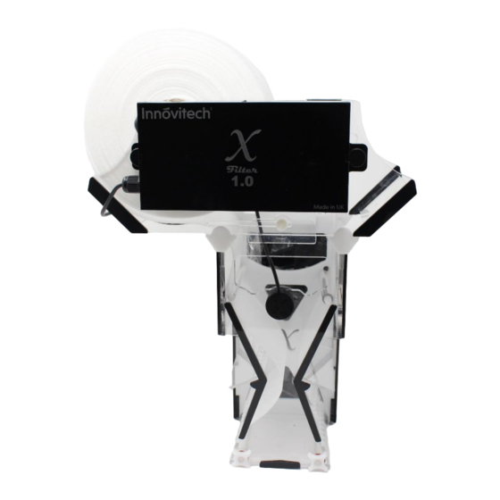
Summary of Contents for Innovitech X Filter 1.0
- Page 1 Copyright – Innovitech LTD...
-
Page 2: Table Of Contents
Version: 1.3 User Manual Contents X Filter Installation ............................3 Plumbing Installation Options ........................7 Vortex Generating Bypass Controllers..................... 9 Fine tuning based on pipe positioning ..................... 10 Filter Media Installation ..........................11 Filter Media Replacement........................16 Maintenance ............................... 17 Alarm &... -
Page 3: Filter Installation
X Filter Installation The X Filter can be separated into three major sections to aid fitting if required. The bottom section could be fully submerged and manouvered to install on sump glass WARNING: Black electronics enclosure should never be submerged under water Using the hooks, hang the filter to the desired position into the sump Position the X Filter based on the... - Page 4 X Filter 1.0 placement Optimum water level: 8 -10cm from bottom of unit Standpipe/flexpipe depth within overflow: 7cm from top of overflow section to magnify the vortex effect when the vortex generating bypass controllers are used. X Filter 1.7 placement...
- Page 5 The adjustable spacer should be used for sump glass thickness up to 6mm. Above 6mm the spacer could be removed. Removing and adjusting the spacer The spacer supports the unit to be level. IMPORTANT NOTICE: It’s important the unit to be set as level as possible in order for the optical sensor to detect water level more accurately and fully take advantage of the...
- Page 6 The top module can be placed left or right from the centre, depending on installation requirements or clearance Top module moves on a track of 7,5cm from one end to another By releasing or tightening the white screws (front screw shown) will allow or restrict movement After setting the position of the top module, ensure front and...
-
Page 7: Plumbing Installation Options
X Filter 1.7: Overflow box measures 6,5cm depth (front to back from sump glass) & 17cm width X Filter 1.0 overflow box can hold a single 50mm (2 in.) or up to two 40mm (1 ½ in.) hard PVC or flexible pipes X Filter 1.7 overflow box can hold a... - Page 8 If flow rate allows it, a hose from another component, such as a reactor, could compliment the filtering and clarity of the water After installation, use the power supply provided and connect it with the cable from the black box with. After powering on the power supply, the green LED on the bottom of the black box will turn...
-
Page 9: Vortex Generating Bypass Controllers
Vortex Generating Bypass Controllers The Vortex Generating Bypass Controllers are positioned at the bottom of the overflow section of the unit. X Filter 1.0 has two (2) bypass controller. X Filter 1.7 has three (3) bypass controllers. The Vortex Generating Bypass... -
Page 10: Fine Tuning Based On Pipe Positioning
Fine tuning based on pipe positioning If there is a single pipe installed, it is advised to be installed towards the side of the overflow box (left or right). This will enhance the vortex generated and aid in better catchment of particles into the filtering section. -
Page 11: Filter Media Installation
Filter Media Installation The clear tube provided is used to hold the roll in place Note: This part is reusable. Do not throw away on filter media change Set the tube through the roll opening The tube is longer than the width of the roll Allow the tube to protrude from the roll equally on each end... - Page 12 Set the media on the side of the unit where the “Innovitech” logo is shown on the black box IMPORTANT: Ensure the outer layer of the roll faces the outer side of the unit Set the media with the clear tube on...
- Page 13 Take the media across and below the optical sensor Pass the media under the lower rod and over the upper rod TIP: At the four (4) top rods, the correct placement of the fleece is OVER – UNDER – UNDER – OVER, as shown in the picture.
- Page 14 Locate the threaded hole on the white backing and screw the rod into place until tight enough to provide a good seal Repeat process on the opposite end WARNING: While screwing rods back into place, do not apply too much force as there’s a risk of breaking the rods off or damaging the thread.
- Page 15 Hold the media tightly on the spool until the spool is set to its final destination otherwise there’s a risk the media will unwind or not set properly TIP: Media sets better on the spool if it’s wet. By sliding the black box outwards, clearance will be created from the direct drive to let the spool sit into place...
-
Page 16: Filter Media Replacement
Filter Media Replacement When the media has finished or is about to finish, prepare to remove the old filter media by slightly tilting the black box to unlock the direct drive. ATTENTION: Before tilting the black box, move the used media roll manually back and forth to UNLOCK the direct drive. -
Page 17: Maintenance
Maintenance After every media change, it’s suggested to wipe the optical sensor with a soft cloth to ensure accuracy and precision is always in check Ensure the sensor is wiped clean at the tip Ensure that the filter is in good condition. There could be some excessive build-up of slime on the rolls. -
Page 18: Alarm & Redundancies
Alarm & Redundancies Alarm There are two LED indicators on the top of the black box: A. Motor turning B. Alarm (Red flashing LED) The alarm will set and permanently stop the motor if the sensor detects an abnormal operation which is tied to the water level not dropping within the filter. -
Page 19: Self-Cleaning Function
2. Reset unit by turning power Off and On 3. Automatic reset if the water level drops below the sensor Designed redundancy: In case there is a serious blockage of the media before the alarm reacts, the designed first point of failure is the uptake spool plastic hex. The hex will snap and allow the powerful motor to move freely till the alarm sets. -
Page 20: Unit Assembly
Unit Assembly Unit is consisted from three main components: Bottom unit (main unit), top unit and electronics/motor assembly Place the top unit on the rails of the bottom unit. The black stoppers of the top unit should face backwards (towards the overflow section of the bottom unit) Insert the white screw through... - Page 21 Repeat the process for the back of the unit to secure the top section to the main unit. Before placing the black box on the top unit, pass the sensor through the hole in the front of the unit. Set the long black screw with the spring to secure the black box with the top unit.
- Page 22 Now that the black box is secure, pass the sensor outside of the bottom unit through the overflow and set the sensor through the designated hole on the bottom (main unit). Secure the sensor with the plastic nut provided and make sure the sensor has a good seal with the bottom (main) unit.
-
Page 23: Detailed Measurements
Detailed Measurements Front View X Filter 1.0 X Filter 1.7 Side View X Filter 1.0 X Filter 1.7... -
Page 24: Troubleshooting
Troubleshooting Issue Solution Further Instructions Unit not powering up Make sure there’s a secure Green LED will turn on at the connection between the cable bottom of the black box. from the black box and the power supply unit. Ensure the power supply receives mains power Alarm LED (Red flashing light) is It is normal for the unit to...
Need help?
Do you have a question about the X Filter 1.0 and is the answer not in the manual?
Questions and answers