Advertisement
Quick Links
Advertisement

Summary of Contents for Elite 4'3" wide compact
-
Page 4: Parts List
PARTS LIST 4 X 4 6 X 4 8 X 4 10 X 4 Nuts and bolts M6 Wire clips Overlap clips Casement stay Stay pins Pins, nuts and bolts M4 Double door lock Self tapping screw Glazing beading—meters Door skids Eaves plates Taped together with one casement stay... -
Page 5: Helpful Hints
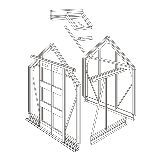
HELPFUL HINTS Please do take your time and be sure to read all instructions carefully before assembling. Consider purchasing the Elite Installation tool kit – see accessory brochure for contents of kit. Do not assemble frame in high winds. The greenhouse frame should be anchored to a permanent foundation. This will not only help secure it against powerful winds but will help prevent breakage of the glass caused by the freezing and thawing process of the earth. - Page 6 INSTALLATION INSTRUCTIONS FOR THE 4’3” WIDE MODEL “COMPACT RANGE” The contents of this carton are divided into the different frame assemblies that collectively make up the completed greenhouse framework. It is recommended that each framework assembly is fully completed before moving onto the next. The contents are as follows: Two side frames Rear end frame...
- Page 7 SIDE FRAME ASSEMBLY Components 1 Combined gutter/eave bar 1 Built in base Glazing bars—1 if 4’ long Bracing angle 1 if 4’ or 6’ long 2 if 6’ long 2 if 8’, 10’ or 12’ long 3 if 8’ long 4 if 10’...
- Page 8 BEWARE OF SHARP EDGES!
-
Page 9: Rear End Assembly
REAR END ASSEMBLY N.B. The roof corner bars are marked “R” on the outside, which indicate that they meet at the ridge and are also mitred at both ends. If you have a painted greenhouse there is no letter “R” on the corner bar. - Page 10 From the main bag of fittings you will require the nuts and bolts, two eave plates and one ridge plate. These are packed with the casement stay and are separated from the main bag of fittings. Components: 1 alloy built in base 2 glazing bars 2 rear end bracing angles 1 rear end horizontal angle...
- Page 11 Check that all angles between built in base and the vertical members are at right angles and that the glazing bars are right into the built in base at the bottom. (Key Point). Tighten all nuts. Slide two extra bolts into the built in base. This will be used later to attach the corner bracket. Slide a bolt into the bolt slot in the built in base section, one at each end.
- Page 12 Attach the rectangular plate (with 3 elongated holes) to the 2 bolts inserted in the glazing bars and the last bolt inserted into the built in base ensuring that the glazing bar is tight down into the angle of the door end cill. Attach the diagonal angle to the top bolt of the rectangular plate. The 2 unoccupied bolts in the built in base sections will be used to anchor the greenhouse to the floor.
- Page 13 DOOR END ASSEMBLY...
- Page 14 DOOR FRAME ASSEMBLY Each Door consists of: 1 unhanded door post 1 handed door post (handed post for left door is different profile to the handed right hand door post) 3 infill panels (1 with pre fabricated lock hole) for lock barrel 1 top and bottom door panels 3 panels of glass which must be fitted during door assembly.
- Page 15 Before fitting the unhanded door post, offer the glass panels to the door (see glazing plan in booklet for glass size guide on door), slide them in from the side. Carefully attach the unhand- ed door post in the same way as before, ensuring the glass is sitting in the correct position (sitting on the beading channels of the door posts) before tightening the screws.
-
Page 17: Fitting The Door Handles
FITTING THE DOOR HANDLES The handles are fitted to the infill panel on each door (choose between 1st or 2nd panel down). Po- sition the handle centrally, and mark the hole position. Drill 7mm diameter holes (2 holes per door), then fit the handles, and secure with a nut and bolt. - Page 18 ROOF VENT ASSEMBLY The roof vent pack has 5 pieces of aluminium and from the main box of fittings you require: 6’ of glazing beading 4 nuts and bolts 2 casement stay pins 1 casement stay 6 M4 stainless steel nuts and bolts PROCEDURE: Identify the slam bar and attach the 2 stay pins to the outer side of the angle using the M4 stainless steel nuts and bolts.
- Page 19 ASSEMBLY OF GREENHOUSE UNIT...
- Page 20 The first operation is to connect the two side frames to the end frames to form the outer shape of the completed structure. Another pair of willing hands would be useful at this stage. Lift the first side frame into its position by the rear end. Slot the eaves bar into the small space between the roof and side corner bar so that the gutter is outside the end frame and the two flanges that form the angle of the roof and side are inside and tight up against the bolt slots of the roof and side corner bar.
- Page 21 Before bolting the bottom of the roof bar to the flange of the eave bar, insert extra bolts. Where the roof vent is to be positioned put an extra one bolt per bar i.e. the roof vent co- vers two glazing bars so two extra bolts per vent. (Key Point). Then attach the final nut and bolt to the eave bar as illustrated.
- Page 22 Do not fit the door at this stage. The greenhouse is now ready for lifting on to its permanent base. If you are fitting the greenhouse onto soft ground, you now need to dig 1 hole (approx. 1 spade width) in each of the 4 corners. You will also need some hard standing under the door end cill.
- Page 23 There are two pieces of flat bar approximately 125mm long that act as small door track supports attached to the top door track either side of the door way. The end of the flat bar with the larger hole bolts to the back of the top door track, the other end will line up with the groove in the face of the corner bar where a small self tapping screw can be in- serted to tighten the flat bar to give extra support.
- Page 24 GLAZING THE STRUCTURE Always handle glass with extreme care as failure to do so can result in injury. HORTICULTURAL AND MULTI-SHEET TOUGHENED GLASS 1. Starting with the bottom pane of one side, offer the pane to the glazing bars. Hold it in place by inserting two of the stainless steel clips six inches from the bottom of the glass.
- Page 25 4’ WIDE COMPACT HORTICULTURAL GLASS/ & MULTI-SHEET TOUGHENED GLASS PLAN Width (mm) Length (mm) Size 4 X 4 6 X 4 8 X 4 If you install a louvre to the greenhouse, it (along with the 610 x 140mm piece of glass in the louvre box) replaces 1 A pane.
- Page 26 Replace pane ‘23’ with 1 piece 610 x 399 (packed with glass shapes), the louvre and then pane ref ‘18’. Elite will automatically assume that you wish to fit the louvre in the rear gable unless you have specified differently at the time of order.
- Page 27 4’ WIDE COMPACT FULL SHEET TOUGHENED GLASS PLAN Code Width (mm) Length (mm) 1197 1197 1456 Size; 4 x 4 6 x 4 8 x 4 YOUR GREENHOUSE IS NOW COMPLETE.
- Page 28 ELITE 1403...
Need help?
Do you have a question about the 4'3" wide compact and is the answer not in the manual?
Questions and answers