
Subscribe to Our Youtube Channel
Summary of Contents for CalUltra UV-CalUltra 12
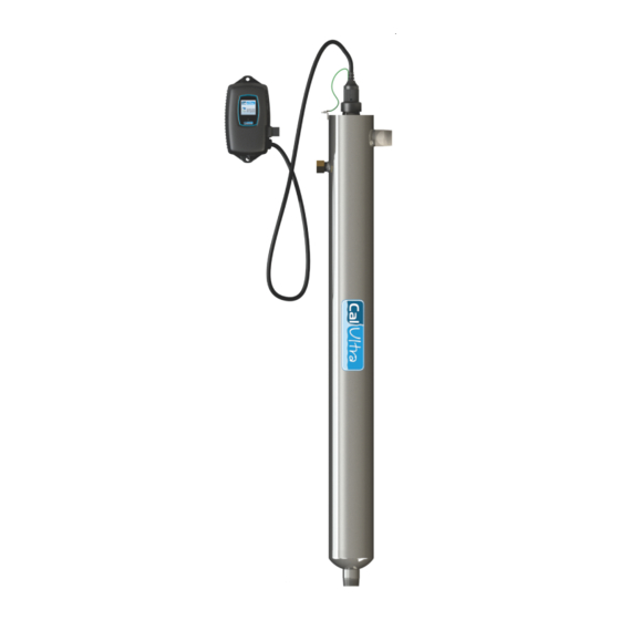
- Page 1 Operation & Installation Instructions CalUltra UV - Standard Systems Model Rated Flow UV-CalUltra 12 12 lpm UV-CalUltra 22 22 lpm UV-CalUltra 41 41 lpm UV-CalUltra 79 79 lpm Remember don’t guess..ASK...
- Page 2 This is a chemical free process which is simple in its concept and effective in its abilities to inactivate microorganisms present in the water supply. Simple maintenance, continuous disinfection and ultimately safe water, CalUltra makes it that easy. P a g e...
-
Page 3: Table Of Contents
Lamp Replacement ....................15 QR Codes ....................... 16 System Troubleshooting..................17 Temperature Management Devices ................. 19 Expansion Modules ......................19 CalUltra UV Standard Output System Specifications ............21 Limited Warranty Statement: ................... 22 Warranty Registration ...................... 23 P a g e... -
Page 4: Safety Considerations
Safety Considerations Although your UV system has been manufactured to the highest safety standards, care must be followed when operating and/or maintaining your system. 1. Before servicing this equipment, disconnect the power cord from the electrical outlet. 2. Energy given off by the UV lamp is harmful to your eyes and skin. NEVER look directly at an illuminated UV lamp without adequate eye protection and always protect your skin from direct exposure to the UV light. -
Page 5: Water Quality Parameters
You can have your water tested at a private analytical laboratory or by your local council. It is always recommended to install pre-filtration of at least 5 microns prior to a CalUltra UV disinfection system. The CalUltra 12 and CalUltra 22 models are already provided with a pre- filter. -
Page 6: Parts List
Parts List Unpack the system and ensure all the components are included with the system. Your system is shipped with the following components that are pre-assembled: CalUltra domestic units GLAND NUT 320006 LAMP KEY O-RING 310038 UV LAMP CONTROLLER Either RC-B56.03-CM... -
Page 7: System Sizing
System Sizing All CalUltra UV systems are rated for a specific flow rate in water that meets the quality parameters on page 5. PLEASE NOTE that increasing the flow above this rating or disinfecting water that does not meet the quality parameters will decrease the dose and therefore compromise the microorganism inactivation. -
Page 8: Installation
UV lamp and/or quartz sleeve (See Figure 2). The controller will require a ground fault circuit interrupter (GFCI or GFI) outlet and should be mounted beside or above the chamber. PLEASE NOTE: All CalUltra UV disinfection systems are intended for indoor use only as they should not be exposed to the elements. - Page 9 ON PRE-BUILT UNITS STEPS 6 & 7 HAVE BEEN PRE-ASSEMBLED Step 6: Once the system has been plumbed in, gently remove the quartz sleeve from its packaging being careful not to touch the length with your hands. The use of cotton gloves is recommended for this procedure as oils from the hands can leave residue on the sleeve and lamp which can ultimately block the UV light from getting to the water.
- Page 10 Step 9: The unit is now ready for water flow. When all plumbing connections have been completed, slowly turn on the water supply and check for leaks. Make sure the by-pass valves are functioning properly and that the water is flowing through the unit. The most common leak is from the o-ring not making a proper seal on the unit.
-
Page 11: System Disinfection
Figure 9. Lamp Connector Figure 8. Lamp Key Installation Step 14: Tighten the captive ground screw to the ground lug on the UV reactor to ensure proper grounding. Figure 10. Ground Screw Connection Step 15: Your system is now ready to be plugged into the appropriate GFCI protected outlet. Refer to the following section before any water is allowed to flow through the system. -
Page 12: Cleaning The Quartz Sleeve
Reinstall the filter cartridge into the filter housing and flush the chlorine solution by opening all taps until chlorine can no longer be detected. Your home has now been completely disinfected with your CalUltra UV system ready to inactivate any microorganisms that enter the home. -
Page 13: Operation
Replace sensor following step 9 from the installation section of the manual. Operation CalUltra systems come with a feature laden controller that incorporates both the lamp driver (ballast) and control features in one water-tight case. Four main controllers are available for the CalUltra systems (depending on your model). -
Page 14: Calultra Controllers
“infinite expandability port” located on the right side of the controller. Simply plug in an optional UV sensor module into the expandability port of a CalUltra controller and the system will now monitor the UV intensity of the system! -
Page 15: Operational Screens (Un-Monitored Version)
On systems without the UV monitor, the default screen shows the CalUltra Home Screen. At any point during operation the user is able to scroll through the CalUltra Home Screen, Lamp life remaining, QR Code, Contact Info and Maintenance Parts screens by pressing the button located on the front of the controller. -
Page 16: Lamp Countdown Sequence
Below 56%, the numbers and warning sign turn red and an audible chirp is given by the ballast every 15 seconds. Below 51%, the screen is solid red and a constant audible alarm is given. This alternates with a screen indicating “water may be unsafe for consumption”. With the solenoid module, the controller de-activates the solenoid valve, shutting off all water flow. -
Page 17: Lamp Replacement
deferral can be repeated up to three times. PLEASE NOTE: At any point after lamp expiration, the water may be unsafe for consumption and should not be consumed without another form of disinfection. Lamp Replacement After the lamp is expired, it must be replaced with the same part number as indicated on the Maintenance Parts screen or on the label on the unit. -
Page 18: System Troubleshooting
System Troubleshooting Hard Alarms: The following give a constant audible alarm. If present, the solenoid valve is closed, and the 4-20, remote alarm and ethernet modules transmit the alarm. System Display Problem Resolution Reset lamp protection circuit -unplug unit for 10 seconds. The system has detected Replace the lamp with the a problem with the... - Page 19 Warning: After any hard alarm, the home or facility should be disinfected. Follow the steps under the “System Disinfection” heading. Boil Water Advisory: If any failure occurs on a CalUltra UV system, the water must not be used for human consumption until the system is returned to a safe operational mode.
-
Page 20: Temperature Management Devices
OPTIONAL EXTRAS Temperature Management Devices Your CalUltra UV system is designed to run continuously to ensure optimal disinfection. However, during periods when no water is drawn through the system, the energy from the disinfection process can cause the temperature of the water inside the chamber to rise. In extreme situations elevated water temperature or the fluctuation in temperature can lower the output of the UV lamp. - Page 21 REMOTE ALARM CONNECTION MODULE: Allows for a connection to a remote device such as a buzzer, light, alarm system, PLC, etc., via a pair of contacts. In normal operation the OK and COM contacts will be connected, and in a fault condition (Low UV, Lamp fail, Power Fail), the Fault and COM contacts will be connected.
-
Page 22: Calultra Uv Standard Output System Specifications
CalUltra UV Standard Output System Specifications CalUltra EQUIPMENT SPECIFICATIONS MODEL CalUltra 12 CalUltra 22 CalUltra 41 CalUltra 79 Flow Rate 23 lpm 41 lpm 77 lpm 150 lpm 16mJ/cm @ 95% UVT Flow Rate 12 lpm 22 lpm 41 lpm... -
Page 23: Limited Warranty Statement
(documentation required for verification). UV LAMPS, UV SENSORS & QUARTZ SLEEVES One (1) year Limited Warranty on all CalUltra ultraviolet lamps, UV sensors and quartz sleeves from the date of original purchase, or installation (proper documentation required for verification). - Page 24 • Water damage is found inside ballast housing or controllers. • Product is installed outdoors in direct contact with the environment (rain). • Product is installed in freezing temperatures. • Product is used in conditions that exceed Calmag’s specifications. WARRANTY SERVICE To obtain service under this warranty, you must first contact CALMAG YORKSHIRE LIMITED’S Customer Service at 01535 210320 to obtain a Goods Return Number and authorisation.
- Page 25 Other UV units available from Calmag in regards to commercial applications. 2 5 | P a g e...
- Page 26 CalUltra EQUIPMENT SPECIFICATIONS Commercial/Industrial Systems (amalgam lamps) CalUltra CalUltra CalUltra CalUltra CalUltra CalUltra CalUltra CalUltra MODEL 1500 2400 Normal Flow Rate 132 lpm 220 lpm 322 lpm 416 lpm 530 lpm 662 lpm 1530 lpm 2360 lpm 30mJ/cm @ 95% UVT...
- Page 27 2 7 | P a g e...
- Page 28 Calmag (Yorkshire) Limited Riverview Buildings Bradford Road, Riddlesden Keighley, West Yorkshire BD20 5JH Phone: 01535 210320 Fax: 01535 210321 E-mail: sales@calmagltd.com Web: www.calmagltd.com Remember don’t guess..ASK PN#910273 Version Date: 02-2018...
Need help?
Do you have a question about the UV-CalUltra 12 and is the answer not in the manual?
Questions and answers