
Subscribe to Our Youtube Channel
Summary of Contents for CHIEF PNP 90 UN 2.0
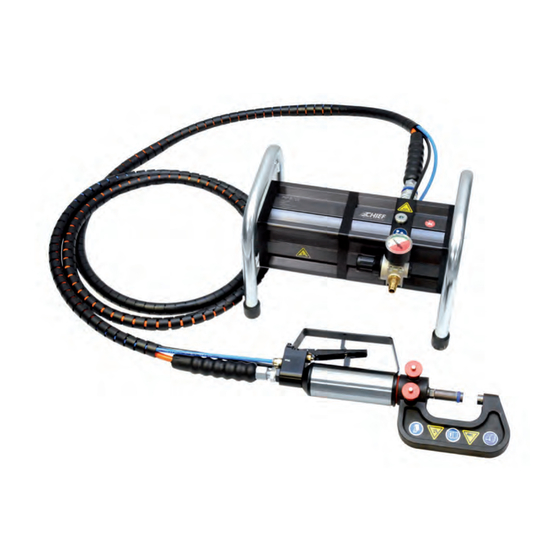
- Page 1 Pneumatic, hydraulic Universal Riveting Tool PNP 90 UN 2.0 Instruction manual Art.-No. CHR2301 Translation of the original instructions...
-
Page 3: Table Of Contents
3. Designations 1. Operating principles 2. Scope of Supply and Accessories 3. Safety instructions 4. Principles for Handling Tool Kit PNP 90 UN 2.0 5. Maintenance 6. Warranty 1. Technical Data, Pump PNP 90 UN 2.0 2. Technical Data, Hose package 3. -
Page 4: Information Regarding This Manual
All handling necessary to ensure correct operation is cally-driven riveting tools must be protected. Contact described in the instruction manual. No work method Chief Automotive for information. other than that expressly approved by the manufac- turer may be used. State of the technology... -
Page 5: Explanation Of Symbols
1.2 Explanation of symbols Some sections of this instruction manual use internationally known warning symbols, warning notes and general instructional symbols. The individual symbols are explained below. Follow all instructions and safety rules. Observe Warning! Please note the Instruction manual General source of danger following! Warning! -
Page 6: Designations
Label Symbol to read the instruction manual 2.1 Operating principles The pneumatic/hydraulic universal tool PNP 90 UN 2.0 coupling can only be connected to the equipment was specially developed for all common riveting opera- when it is depressurized. tions in thin sheet metal structures. -
Page 7: Scope Of Supply And Accessories
CHR2301 2.2.2 CHR2204 2.2.3 CHR2203 Scope of supply complete kit PNP 90 UN 2.0 Accessories (not part of the complete kit) Art.-No. CHR2301 1x Rivet clamp NB 115, Art.-No. CHR2204 1x Pressure intensifier PNP 90 1x Rivet clamp NB 230, Art.-No. CHR2203... -
Page 8: Safety Instructions
2.3 Safety instructions The hydraulic tool kit is strictly approved Because metallic parts can break up and only for the purposes intended by the fly off with high energy if the tool is faulty manufacturer. or operated incorrectly, protective gloves and a face mask must strictly be worn for all Only genuine accessories may be used. -
Page 9: Principles For Handling Tool Kit Pnp 90 Un
2.4 Principles for Handling the PNP 90 UN 2.0 Tool Kit Risk of injury Warranty Route all supply lines in a manner that pre- The manufacturer accepts no liability for da- vents people from tripping over them. Cor- mage or injury caused by improper repair or... -
Page 10: Maintenance
External cleaning by the med by professionals with proper training by Every 6 customer Chief Automotive Technologies. For further months or Check oil level and information on servicing and training, please if required... -
Page 11: Warranty
In addition, the warranty becomes invalid if the tool is not used as described in the instruction manual. In the event of defect or fault, Chief Automotive Technologies will only repair or re- place faulty parts at its own discretion. -
Page 12: Technical Data Pump Pnp 90 Un
01.01.1601 3.1 Technical Data Pump PNP 90 UN 2.0 tahl am 01.01.1601 o.stahl am 01.01.1601 3.1.1 3.1.2 Pump PNP 90 UN 2.0 3.1.3 Length 330 mm Width 230 mm Height (incl. handle) 213 mm Weight 7.665 kg Max. -
Page 13: Technical Data, Hydraulic Actuator Hp 35 Un
3.3 Technical Data, Hydraulic Actuator HP 35 UN 3.3.1 3.3.2 Hydraulic actuator HP 35 UN 3.3.3 Length 267 mm Width 50 mm Height (incl. handle) 117 mm Weight 2.310 kg Max. operating pressure 600 bar Travel 15 mm... -
Page 14: Technical Data, Rivet Clamp
3.4 Technical Data, Rivet Clamp 3.4.1 3.4.2 Rivet clamp NB 40 3.4.3 3.4.4 3.4.5 3.4.6 Rivet clamp NB 1 15... - Page 15 3.4.7 3.4.8 364.1 44.5 364.1 364.1 44.5 44.5 Rivet clamp NB 230 3.4.9 Technical data Rivet clamp NB 40 Rivet clamp NB 1 15 Rivet clamp NB 230 Part number CHR2405 CHR2204 CHR2203 Length* 106 mm 213 mm 364.1 mm Width 45 mm 44 mm...
-
Page 16: Technical Data, Riveting Tool Kit Rivkit Un
3.5 Technical Data, Riveting Tool Kit RIVKIT UN 2.0 3.5.1 CHR2403 Riveting Tool Kit RIVKIT UN 2.0 Kit number Item/Description/Article number Item/Description/Article number A Setting head, B Closing head, Set: CHR2403-3 3 mm rivet 3 mm rivet C Setting head, D Closing head, Set: CHR2403-4 5 mm rivet... -
Page 17: Start-Up
4.1 Start-up 4.1.1 4.1.2 4.1.2 G1/4“ G1/4“ 4.1.3 4.1.4 R1/4“ R1/4“ The equipment is supplied from the factory without a compressed air connection. The pressure regulator has a G1/4“ (internal thread) connection thread. 4.1.1/4.1.2 The pressure regulator is supplied with a closing cap fitted. -
Page 18: Riveting Tool Preparation And Hydraulic Actuator Connection
4.2 Riveting Tool Preparation and Hydraulic Actuator Connection 4.2.1 4.2.2 4.2.3 4.2.4 4.2.5 4.2.5 Connect the pneumatic hoses. Make sure that the black hose is attached to the marked coupling. Before using the equipment, check the condition of the hydraulic actuator with add-on component and hoses. - Page 19 4.2.7 4.2.8 max. 6 bar / 87 psi 4.2.7 Connect compressed air to the pressure regulating val- ve and set the pressure. 4.2.8 Never use pressure over the permitted value of 6 bar or 87 psi. This could cause equipment damage or even physical inju-...
-
Page 20: Connecting The Hydraulic Actuator To The Hose
4.3 Connecting the Hydraulic Actuator to the hose 4.3.1 4.3.2 4.3.3 4.3.4 4.3.5 4.3.6 4.3. 1 /4.3.2 4.3.5/4.3.6 The operating unit and both hose package connections are When connecting the pneumatic control hoses, make sure provided with protective caps. Remove the protective caps that the black hose is attached to the coupling indicated. -
Page 21: Safe Set-Up And Positioning Of Equipment
4.3 Safe Set-Up and Positioning of Equipment 4.4.1 Ensure that the high-pressure pump is 4.4.2 always placed on a non-slip surface and that the hoses are routed in a way that prevents them from getting damaged or pinched off. The hoses must also be routed in a way that prevents people from tripping over them. -
Page 22: Connecting The Tool To The Hydraulic Actuator
4.5 Connecting the Tool to the Hydraulic Actuator 4.5.1 4.5.2 4.5.1/4.5.2 4.5.3 4.5.4 Select tool and prepare locking pins. The tool is carefully pushed onto the mounting adapter by the mounting hole. The indexing pin in the mounting adaptor must engage in the corresponding slots in the mounting hole. -
Page 23: Riveting Tool Kit Rivkit Un 2.0 - Mounting And Intended Use
4.6 Riveting Tool Kit RIVKIT UN 2.0 – Mounting and Intended Use 4.6.1 4.6.2 Three rivet clamps are currently available for use 4.6.3 with the RIVKIT UN 2.0 riveting tool kit: Rivet clamp Part No. Opening depth NB 40 CHR2405 bis 40 mm NB 115 CHR2204... -
Page 24: Pressing Out Rivets
5.1 Pressing out Rivets 5.1.2 CHR2403-8 5.1.1 5.1.3 5.1.4 5.1.5 Old or defective rivets often need to be removed from the sheet metal structure when repairing body panels. 5.1.1 – 5.1.5 Instead of drilling out the old rivets, they can be pressed out of the sheet metal structure using the extraction mandrel and extraction die (kit CHR2403-8), thereby minimizing damage. -
Page 25: Punching And Calibration Of Holes For Flow Form Rivets
5.2 Punching and Calibration of Holes for Flow Form Rivets 5.2.1 CHR2403-7 5.2.2 5.2.1 – 5.2.4 5.2.3 There is no need to drill holes in sheet joints when using flow form rivets. Punch and punch die (kit CHR2403- 7) enable precise hole punching and simultaneous calibration of rivet holes. -
Page 26: Setting Flow Form Rivets
5.3 Setting Flow Form Rivets 5.3.1 CHR2403-6 5.3.2 5.3.3 5.3.4 5.3.1 5.3.5 The flow form rivets are installed using the die head and corresponding closing head (kit CHR2403-6) intended for this purpose. 5.3.2 It is important that the die head with the centering lug engages in the corresponding depression in the rivet. -
Page 27: Installation Of Semi-Tubular Punch Rivets
5.4 Installation of Semi-Tubular Punch Rivets 5.4.1 CHR2403-3 5.4.2 CHR2403-4 Ø 3 mm Ø 5 mm 5.4.3 5.4.4 5.4.1 – 5.4.2 5.4.5 Extra care must be taken to ensure that the rivets that are used are properly seated when installing semi- tubular punch rivets. -
Page 28: Checking Riveting Results
5.5 Checking Riveting Results 5.5.1 – 5.5.3 5.5.1 5.5.2 The results must be checked after the riveting opera- tion. If the installed rivet does not meet quality requi- rements, the reason for the fault must be determined. If the quality of the installed rivet is acceptable, the work process can be repeated. -
Page 29: Completing An Operation And Riveting Tool Storage
5.7 Completing an Operation and Riveting Tool Storage 5.7.1 5.7.1 Always disconnect the compressed air sup- ply from the pump after riveting and during work interruptions. 5.7.2 Then disconnect the control hoses and seal the openings. Make sure that the disconnected hoses ne- ver make contact with the dirty floor or the ground. -
Page 30: Hydraulic Pump Maintenance
6.1 Hydraulic Pump Maintenance 6.1.1 6.1.2 6.1.3 6.1.3 6.1.4... - Page 31 6.1.6 6.1.5 280 cm / 9,47 fl oz 6.1.2 – 6.1.4 Draining oil 6.1.7 Undo the sealing plug on the top of the pump and let the used hydraulic oil flow into a suitable container. 6.1.5, 6.1.6 Filling oil Fill with fresh oil that complies with the specifications. The nominal filling volume is around 280 cm /9,47 fl oz.
- Page 32 www.chiefautomotive.com...
-
Page 33: Replacement Part List
6.2 Replacement Part List Pos.-No. Part No. Title CHR2402 PNP 90 pressure intensifier (pump) Hose package CHR2401 Hydraulic actuator HP 35 UN CHR2404 Ball lock pin CHR2405 Rivet clamp NB 40 CHR2204 Rivet clamp NB 115 Rivet clamp NB 230 CHR2203 (composed of pos. -
Page 34: Troubleshooting
6.3 Troubleshooting Problem Cause Remedy Page No air connected Connect compressed air Control lines not connected or Connect control lines correctly and make sure incorrectly connected they are properly seated Insufficient air pressure Check air supply Pump does not Connect hydraulic hose as described in the Hydraulic hose not connected instruction manual Air pressure not correctly set... -
Page 35: Disposal
Chief makes no written, express or implied warranty whatsoever of merchantability or fitness for a particular purpose or otherwise regarding the equipment or any part of the product other than the limited one-year warranty stated in chapter 2.6. - Page 36 Chief Automotive Technologies Service 996 Industrial Drive Madison, IN 47250 Phone: 800-445-9262 Fax: 866-275-0173...
Need help?
Do you have a question about the PNP 90 UN 2.0 and is the answer not in the manual?
Questions and answers