Table of Contents

Summary of Contents for Easy xLogic SuperRelay
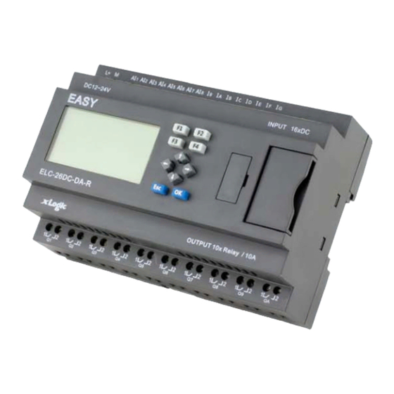
- Page 1 LOST COST FACTOR U p d a t e d : D e c e m b e r 2 0 0 8 The xLogic SuperRelay is an Easy Electronic Co., Ltd manufactured R E P L A C E S M I N I product.
- Page 2 Content. Introduction Getting started Installation and wiring Functions Configuring Applications Software Technical data...
- Page 3 The xLogic SuperRelay is available in 120V/240V AC or 12V and 24V DC versions, making it the ideal solution for relay replacement, or simple...
- Page 4 User’s Manual xLogic SuperRelay Valid range for this manual The manual applies to devices of the series ELC-18, ELC-12 and ELC-E Safety Guideline This manual contains notices you have to observe in order to ensure your personal safety, as well as to prevent damage to property. The notices referring to your personal safety are highlighted in the manual by a safety alert symbol, notices referring to property damage only have no safety alert symbol.
- Page 5 Trademarks All names identified by xLogic are registered trademarks of the EASY. The remaining trademarks in this publication may be trademarks whose use by third parties for their own purposes could violate the rights of the owner.
-
Page 6: Table Of Contents
User’s Manual xLogic SuperRelay Contents 1. General Introduction to xLogic 2. Installation/remove xLogic 2.1 DIN rail mounting 2.2 Wiring the xLogic 2.2.1Connecting the power supply 2.2.2 Connecting xLogic inputs 2.2.3 Connecting xLogic outputs 3. Programming xLogic 3.1 General Input & Output functions 3.1.1 Inputs... - Page 7 SuperRelay Users Manual 3.4.14 Hours counter 3.4.15 Threshold trigger 3.4.16 Latching relay 3.4.17 Pulse relay 3.4.18 Message text 3.4.19 Softkey 3.4.20 Shift register 3.4.21 Analog comparator 3.4.22 Analog threshold trigger 3.4.23 Analog amplifier 3.4.24 Analog value monitoring 3.4.25 Analog differential trigger 3.4.26 Analog multiplexer...
-
Page 8: General Introduction To Xlogic
User’s Manual xLogic SuperRelay xLogic Software Connecting the xLogic to a PC Appendix Technical data A.1 General technical data A.2 Technical data: xLogic (ELC series) Relay switch life... - Page 9 1. General Introduction to xLogic Overview xLogic SuperRelay is a universal logic module made by Easy Electronic Co., Ltd and marketed by Inter Reps Ltd. to selected distributors around the globe. xLogic SuperRelay is a compact and expandable CPU replacing mini PLCs, multiple timers, relays and counters.
- Page 10 Low cost pricing Some of the things xLogic can do for you? The xLogic SuperRelay provides solutions for commercial, industrial, building and domestic applications such as lighting, pumping, ventilation, shutter operations or in switching cabinets. The application field is widespread and these are just a few to mention.
- Page 11 SuperRelay Users Manual xLogic devices: xLogic Basic is available in two voltage classes: *Classes 1: DC12-24V: i.e.: ELC-18DC Series and ELC-12DC Series. *Classes2:AC110-240V: i.e.: ELC-18AC Series and ELC-12AC Series In the versions: * With Display: ELC-18 Series (12 inputs and 6 outputs)
- Page 12 User’s Manual xLogic SuperRelay computer has no standard serial port. xLogic: Ethernet module(type:ELC-Ethernet) It is called Ethernet module, used to connect xLogic main modules in different places to enormous Ethernet to buildup a huge monitoring and control system. It contains DC and AC two types.
-
Page 13: Ethernet Network
Ethernet Module box to the Ethernet. The project down- and upload to and from the main modules and the communication between the main modules happens over the Ethernet network. Furthermore the visualization of the whole system is possible and easy to realize a personal computer. -
Page 14: Can Bus
User’s Manual xLogic SuperRelay CAN bus The communication between the main module and the expansion modules or the remote I/O happens over a CAN bus. CAN is a widely used bus system(only ELC-18 Series available, not applied to ELC-12 series)... - Page 15 SuperRelay Users Manual Series name Points of input and output Supply power AC or DC Digital/Analog D: digital DA: digital/analog L: with photoelectricity isolation Output format R: relay T: transistor TN = “NPN” transistor; TP= “PNP” transistor Model name (expansion module):...
- Page 16 User’s Manual xLogic SuperRelay ELC- DC24V 8 analog 4 relays (10A) no 12DC-DA-R /digital ELC-12DC-DA DC24V 8 analog 4 transistor 1 ch(Q4) /digital (0.3A) ELC- AC110~ 12 digital 6 relays (10A) 18AC-R AC240V ELC- AC110~ 6 relays (10A) 18AC-L-R AC240V...
- Page 17 User’s Manual xLogic SuperRelay 2. ELC-12 Series Main Module 3. ELC-E Series Expansion Module...
-
Page 18: Installation/Remove Xlogic
SuperRelay User’s Manual 2. Installing/removing xLogic Dimensions The xLogic installation dimensions are compliant with DIN 43880. xLogic can be snap-mounted to 35 mm DIN rails to EN 50022 or on the wall. xLogic width: ELC-12 Series Main Module has a width of 72mm. -
Page 19: Din Rail Mounting
User’s Manual xLogic SuperRelay The figure below shows you an example of the installation and removal of an ELC-12AC main module. The measures shown apply to all other ELC-12 Series versions and ELC-18 Series versions and expansion modules. W a r n i n g Always switch off power before you “remove”... -
Page 20: Wiring The Xlogic
SuperRelay User’s Manual 2.2 Wiring the xLogic Wire the xLogic using a screwdriver with a 3-mm blade. You do not need wire ferrules for the terminals. You can use conductors with cross-sections of up to the following thicknesses: 1 x 2.5 mm ... -
Page 21: Connecting Xlogic Inputs
User’s Manual xLogic SuperRelay .Connecting xLogic inputs 2.2.2 1. Requirements At the inputs you connect sensor elements such as: momentary switches, switches, light barriers, daylight control switches etc. ELC-18AC ELC-18DC ELC-12DC ELC-12AC ELC-E-16DC ELC-E-16AC Signal status 0 <3VDC <40VAC <1.5mA <0.24mA... - Page 22 SuperRelay User’s Manual Note: 1. For ELC-18DC Series and ELC-12DC Series versions. That can receive analog input. They can be set to analog input or switching input as either may be used in the program. They will be recognized as analog inputs when the input terminal is...
- Page 23 User’s Manual xLogic SuperRelay * ELC-Analog Inputs...
-
Page 24: Connecting Xlogic Outputs
SuperRelay User’s Manual 2.2.3 Connecting xLogic Outputs 1. Requirement for the relay output Various loads such as lamp, fluorescent tube, motor, contact, etc., can be connected to the outputs of xLogic. The maximum ON output current that can be supplied by xLogic , is 10A for the resistance load and 2A for the inductive load. - Page 25 User’s Manual xLogic SuperRelay Notes (PNP): * The load connecting voltage must be ≤80VDC and it must be DC. * The “+” terminal of the output wiring must be connected with the DC positive voltage, and it must be connected with the “L+” terminal of the xLogic power a load must be connected with the “-”...
-
Page 26: Programming Xlogic
SuperRelay User’s Manual 3 Programming xLogic ELC series adopts the programming methods by the use of function blocks. A total of 8 general function blocks, 29 special function blocks, and 6 input & output function blocks are configured. And each block can achieve a specific control function independently, e.g. -
Page 27: Cursor Keys
User’s Manual xLogic SuperRelay 3.1.2 Cursor keys Up to four cursor keys are available to you. Cursor keys are programmed for the circuit program in the same ways as other inputs. Cursor keys can save switches and inputs, and allow operator control of the circuit program. -
Page 28: Analog Inputs
SuperRelay User’s Manual 3.1.6 Analog inputs You can use up to 88 analog inputs. In your block configuration, you can assign a new input terminal to an input block, provided this terminal is not already used in the circuit program. -
Page 29: Basic Functions List - Gf
User’s Manual xLogic SuperRelay 3.2 Basic functions list – GF Basic functions represent simple logical elements of Boolean algebra. You can invert the inputs of individual basic functions , i.e. the circuit program inverts a logical “1” at a relevant input to a logical “0”; if “0” is set at the input, the program sets a logical “1”. - Page 30 SuperRelay User’s Manual...
-
Page 31: And With Edge Evaluation
User’s Manual xLogic SuperRelay 3.2.2 AND with edge evaluation The output of an AND with edge evaluation is only 1 if all inputs are 1 and at least one input was 0 during the last cycle. The output is set to 1 for the duration of one cycle and must be reset to 0 for the duration of the next cycle before it can be set to 1 again. -
Page 32: Nand With Edge Evaluation
SuperRelay User’s Manual Logic table of the NAND block: Input 1 Input 2 Input 3 Input 4 Output 3.2.4 NAND with edge evaluation The output of a NAND with edge evaluation is only 1 at least one input is 0 and all inputs were 1 during the last cycle. - Page 33 User’s Manual xLogic SuperRelay Timing diagram of a NAND with edge evaluation 3.2.5 OR The output of an OR is 1 if at least one input is 1 hat, i.e. when it is closed. A block input that is not used (x) is assigned: x = 0.
-
Page 34: Nor
SuperRelay User’s Manual 3.2.6 NOR The output of a NOR (NOT OR) is only 1 if all inputs are 0 hat, i.e. when they are open. When one of the inputs is switched on (logical 1 state), the output is switched off. -
Page 35: Xor
User’s Manual xLogic SuperRelay 3.2.7 XOR The XOR (exclusive OR) output is 1 if the signal status of the inputs is different. A block input that is not used (x) is assigned: x = 0. Logic table of the XOR function:... -
Page 36: Designation Of The Inputs
SuperRelay User’s Manual retentive functions and various parameter assignment options, which allow you to adapt the circuit program to suit your own requirements. This section provides you with a brief overview of input designations and with some particular background information on SFs. The SFs in particular are described in Chapter 4 3.3.1 Designation of the inputs... -
Page 37: Time Response
User’s Manual xLogic SuperRelay (times, on/off thresholds etc.). No (Cam): This input will not be connected. Here, you configure the time patterns. P (Priority): This is an open input. Here, you define priorities and specify whether a message is to be acknowledged in RUN. -
Page 38: Backup Of The Real-Time Clock
SuperRelay User’s Manual time-base and corrected. The resultant maximum timing in accuracy is ± 5 s/day. 3.3.3 Backup of the real-time clock Because the internal real-time clock of an xLogic is backed up, it continues operation after a power failure. The ambient temperature influences the backup time. -
Page 39: Parameter Protection
User’s Manual xLogic SuperRelay 3.3.5 Parameter protection In the parameter protection settings, you can determine whether the parameters can be displayed and edited in xLogic parameter modify mode or not. 3.3.6 Calculating the gain and offset of analog values A sensor is connected to the analog input and converts a process variable into an electrical signal. - Page 40 SuperRelay User’s Manual A pressure sensor converts a pressure of 1000 mbar into a voltage of 0 V, and a pressure of 5000 mbar into a voltage of 10 V. Actual value = (internal value . gain) + offset, thus 1000 = (0·A) + B, i.e.
-
Page 41: Special Functions List - Sf
User’s Manual xLogic SuperRelay 3.4 Special functions list – SF When you create your circuit program in xLogicsoft, you find the special function blocks in the SF list. You can invert the inputs of SFs individually, i.e. the circuit program converts a logical “1”... - Page 42 SuperRelay User’s Manual Parameter You select the required function via the block number. Time-base can be adjusted. The value of "T" can be set/modified in parameter mode. For information about how to modify,refer to chapter 4.2.2 please. For information on the validity and accuracy of the time base, refer to the xLogic...
-
Page 43: Off-Delay
User’s Manual xLogic SuperRelay The output is reset to 0 when input Trg is 0. 3.4.2 Off-delay Short description The output with off delay is not reset until a defined time has expired. Connection Description Input Trg Start the off delay time with a negative edge (1 to 0 transition) -
Page 44: On-/Off-Delay
SuperRelay User’s Manual Description of the function Output Q is set to 1 momentarily with a 0 to 1 transition at input Trg. At the 1 to 0 transition at input Trg, xLogic retriggers the current time T, and the output remains set. - Page 45 User’s Manual xLogic SuperRelay Output Q Q is switched on upon expiration of a configured time T if Trg is still set. It is switched off again upon expiration of the time T if Trg has not been set again.
-
Page 46: Retentive On-Delay
SuperRelay User’s Manual 3.4.4 Retentive on-delay Short description A one-shot at the input triggers a configurable time. The output is set upon expiration of this time. Connection Description Input Trg Trigger the on delay time via the Trg (Trigger) input. -
Page 47: Wiping Relay (Pulse Output)
User’s Manual xLogic SuperRelay Description of the function The current time Ta is triggered with a 0 to 1 signal transition at input Trg. Output Q is set to 1 when Ta reaches the time T. A further pulse at input Trg does not affect Ta. -
Page 48: Edge Triggered Wiping Relay
SuperRelay User’s Manual Description of the function With the input signal Trg = 1, output Q is set to 1. The signal also triggers the time Ta, while the output remains set. When Ta reaches the value defined at T (Ta=T), the output Q is reset to 0 state (pulse output). -
Page 49: Asynchronous Pulse Generator
User’s Manual xLogic SuperRelay Timing diagram = 0; N = 1 Description of the function With the change at input Trg to 1, the time T (time low) is triggered. After the time T has expired, output Q is set to 1 for the duration of the time T (time high). -
Page 50: Random Generator
SuperRelay User’s Manual Parameter The value of "T "can be set/modified in parameter mode. For information ", "T H L about how to modify ,refer to chapter 4.2.2 please. Timing diagram Description of the function You can set the pulse/pause ratio at the TH (Time High) and TL (Time Low) parameters. - Page 51 User’s Manual xLogic SuperRelay (Enable) triggers the on delay for the random generator. The negative edge (1 to 0 transition ) triggers the off delay for the random generator. Parameter The on delay is determined at random and lies between 0...
-
Page 52: Stairway Lighting Switch
SuperRelay User’s Manual 3.4.9 Stairway lighting switch Short description The edge of an input pulse triggers a configurable time. The output is reset when this time has expired. An off warning can be output prior to the expiration of this time. -
Page 53: Multiple Function Switch
User’s Manual xLogic SuperRelay You can change the prewarning time base and the period. Time base Prewarning time Prewarning period Seconds 750 ms 50 ms Minutes 15 s Hours 15 min 1 min * makes sense only for programs with a cycle time of < 25 ms Description of the function Output Q is set to 1 with a 0 to 1 signal transition at input Trg. - Page 54 SuperRelay User’s Manual Connection Description Input Trg With a signal at input Trg (Trigger) you set output Q (continuous light), or reset Q with off delay. Output Q can be reset with a signal at the Trg input. Input R You set the current time Ta, and reset the output to 0, with a signal at input R.
-
Page 55: Weekly Timer
User’s Manual xLogic SuperRelay Output Q is reset when the Ta = T. Before the off delay time (T - T ) has expired, you can output an off prewarning that resets Q for the duration of the off prewarning time T . - Page 56 SuperRelay User’s Manual No1: Daily: 06:30 h to 08:00 h No2: Tuesday: 03:10 h to 04:15 h No3: Saturday and Sunday: 16:30 h to 23:10 h Description of the function Each weekly timer is equipped with three cams. You can configure a time hysteresis for each individual cam.
-
Page 57: Yearly Timer
User’s Manual xLogic SuperRelay Backup of the real-time clock The internal real-time clock of xLogic is buffered against power failure. The buffering time is influenced by the ambient temperature, and is typically 10 hours(ELC-18) or 72 hours(ELC-12) at an ambient temperature of 25°C. - Page 58 The calendar icon offers you an easy way of setting the date. It opens a window where you can set the days and months by clicking the relevant buttons.
-
Page 59: Sample Configuration
User’s Manual xLogic SuperRelay Sample configuration The output of a xLogic is to be switched on annually, from 1st of March to 4th of April and from 7th of July to 19th of November. This requires two blocks for configuring the specific on times. -
Page 60: Up/Down Counter
SuperRelay User’s Manual Create a logical link of the blocks via a standard OR block. The OR output is 1 if at least one of the yearly timer switches is set. 3.4.13 Up/Down counter Short description An input pulse increments or decrements an internal value, depending on the parameter setting. - Page 61 User’s Manual xLogic SuperRelay Connection Description Input R You reset the output and the internal counter value to zero with a signal at input R (Reset) Input Cnt This function counts the 0 to 1 transitions at input Cnt. It does not count 1 to 0 transitions.
-
Page 62: Hours Counter
SuperRelay User’s Manual The function increments (Dir = 0) or decrements (Dir = 1) the internal counter by one count with every positive edge at input Cnt. You can reset the internal counter value to '000000', with a signal at the reset input R. As long as R=1, the output is 0 and the pulses at input Cnt are not counted. - Page 63 User’s Manual xLogic SuperRelay Connection Description Input R A positive edge (0 to 1 transition) at input R resets output Q and sets a configured value MI at the counter for the duration of the time-to-go (MN). Input En En is the monitoring input. xLogic scans the on-time of this input.
- Page 64 SuperRelay User’s Manual MI = Configured time interval MN = Time-to-go OT = Total time expired since the last 1 signal at the Ral input These values are principally held retentive! Parameter The value of "MI" can be set and modified in parameter mode. For information about how to modify, refer to chapter 4.2.2 please.
-
Page 65: Threshold Trigger
User’s Manual xLogic SuperRelay Limit value of OT The value of the operating hours in OT are retained when you reset the hours counter with a signal at input R. The hours counter OT continues the count as long as En = 1, irrespective of the status at the reset input R. - Page 66 SuperRelay User’s Manual Connection Description Input Fre The function count 0 to 1 transitions at input Fre. ! to 0 transitions are not counted. Inputs I8(ELC-12) or IB/IC(ELC-18) for fast counts max. 99 kHz. Any other input or circuit element for low frequencies...
-
Page 67: Latching Relay
User’s Manual xLogic SuperRelay Calculation rule If the threshold (On) > threshold (Off), then: Q = 1, if fa >= On Q = 0, if fa < Off. If the threshold (On) < threshold (Off), then Q = 1, if On <= fa <... -
Page 68: Pulse Relay
SuperRelay User’s Manual Description of the function The latching relay represents a simple binary memory logic. The output value depends on the input states and the previous status at the output. Logic table of the latching relay: Remark Status unchanged... -
Page 69: Message Text
User’s Manual xLogic SuperRelay No parameter of Latching relay can be set/modified in parameter mode . Timing diagram Description of the function The status of output Q changes with each 0 to 1 transition at input Trg and if both S and R = 0, i.e. - Page 70 SuperRelay User’s Manual Parameter or actual value of another, already configured function (see "Visible parameters or actual values") Time: Shows the continuously updated time-of-day Date: Shows the continuously updated date EnTime: Shows the time of the 0 to 1 transition...
- Page 71 User’s Manual xLogic SuperRelay "General" area Here you will find the following settings:· Priority of the message text Check box for message text acknowledgement "Blocks" area Shows a list of all the circuit program blocks and their parameters.
- Page 72 SuperRelay User’s Manual " "Block parameters" or "General parameters area into the message text. 6 "Messages" area You arrange the message text in this area. Information entered in this area corresponds with that on the xLogic display. 7 "Delete" button Button for deleting entries from the "Messages"...
-
Page 73: Softkey
User’s Manual xLogic SuperRelay 3.4.19 Softkey Short description This SFB provides the action of a mechanical pushbutton or switch. Connection Description Input En Output Q is set with a 0 to 1 signal transition at input En (Enable) and if, in addition, 'Status=On' has been confirmed in configuration mode. -
Page 74: Shift Register
SuperRelay User’s Manual Description of the function The output is set, when input En is set and the 'Status' parameter is set to 'On' and confirmed with OK. This action is performed irrespective of a configured switch or pushbutton function. - Page 75 User’s Manual xLogic SuperRelay input Trg (Trigger). A 1 to 0 transition is irrelevant. Input Dir You define the shift direction of the shift register bits S1...S8 at the Dir input: Dir = 0: shift up (S1 >> S8) Dir = 1: shift down (S8 >> S1)
-
Page 76: Analog Comparator
SuperRelay User’s Manual Q outputs the value of the configured shift register bits. If retentivity is not enabled, the shift function restarts at S1 or S8 after a power failure. Note The special function shift register can be used only once in the circuit program. - Page 77 User’s Manual xLogic SuperRelay Range of values: 0, 1, 2, 3 Output Q Q is set or reset depending on the set thresholds. Parameter p (number of decimals) Applies only to Ax, Ay, Delta, On and Off values displayed in a message text.
-
Page 78: Analog Threshold Trigger
SuperRelay User’s Manual Output Q is set or reset depending on the difference of the actual values Ax - Ay and the set thresholds. See the following calculation rule. Calculation rule If threshold On ≥Threshold Off, then: Q = 1, if (actual value Ax - actual value Ay) > On Q = 0, if (actual value Ax - actual value Ay) ≤Off. - Page 79 User’s Manual xLogic SuperRelay Connection Description Input Ax Input the analog signal to be evaluated at input Ax. Use the analog inputs AI1...AI8, the analog outputs AQ1 and AQ2. 0 - 10 V is proportional to 0 - 1000 (internal value).
- Page 80 SuperRelay User’s Manual Description of the function The function reads the value of the signal at the analog input Ax. This value is multiplied by the value of parameter A (gain). Parameter B (offset) is added to the product, hence (Ax ∙Gain) + Offset = Actual value Ax.
-
Page 81: Analog Amplifier
User’s Manual xLogic SuperRelay 3.4.23 Analog amplifier Short description This SFB amplifies an analog input value and returns it at the analog output. Connection Description Input Ax Input the analog signal to be amplified at input Ax. Use the analog inputs AI1...AI8, the analog outputs AQ1 and AQ2. -
Page 82: Analog Value Monitoring
SuperRelay User’s Manual This value is multiplied by the gain parameter A. Parameter B (offset) is added to the product, i.e. (Ax ∙gain) + offset = Actual value Ax. 3.4.24 Analog value monitoring Short description This special function saves the process variable of an analog input to memory, and sets the output when the output variable exceeds or drops below this stored value plus a configurable offset. - Page 83 User’s Manual xLogic SuperRelay Applies only to the display of Aen, Ax and Delta values in a message text. Timing diagram Description of the function A 0 to 1 transition at input En saves the value of the signal at the analog input Ax. This saved process variable is referred to as Aen".
-
Page 84: Analog Differential Trigger
SuperRelay User’s Manual 3.4.25 Analog differential trigger Short description The output is set and reset depending on a configurable threshold and a differential value. Connection Description Input Ax You apply the analog signal to be analyzed at input Ax. - Page 85 User’s Manual xLogic SuperRelay Timing diagram B: Function with positive difference Delta Description of the function The function fetches the analog signal at input Ax. Ax is multiplied by the value of the A (gain) parameter, and the value at parameter B (offset) is added to product, i.e.
-
Page 86: Analog Multiplexer
SuperRelay User’s Manual See the timing diagram A. When you set a positive differential value Delta, the On threshold < the Off threshold, and Q = 1, if: On ≤ the actual value Ax < Off. See the timing diagram B. - Page 87 User’s Manual xLogic SuperRelay Parameter P (number of decimal places) Applies only to the display of AQ, V1, V2, V3 and V4 values in a message text. Timing Diagram Description of Function If input En is set, then the function issues one of 4 possible analog values V1 to V4 at the output AQ, depending on the parameters S1 and S2.
-
Page 88: Hmi Block
SuperRelay User’s Manual 3.5 HMI (Human Machine Interface) Block 3.5.1System cover This block cannot directly be found in the block list ,however, it is set as default by system of xLogic, hence system cover can be available if you follow the below procedures : use your mouse to left-click “Tools”... -
Page 89: System Input/Output
User’s Manual xLogic SuperRelay 3. "Delete" button Button for deleting the “Messages” in the first and second line. 3.5.2 System input/output Short description Display the status of the input and output of the main and expansion modules. Particular characteristics to be noted when configuring... - Page 90 SuperRelay User’s Manual 1. "General" area Here you will find the following settings: Priority of the system input and output. 2. "Blocks" area Displaying all extendable and main modules can be inserted 3. "Insert" button Button for inserting the selected blocks to the “Message” area.
-
Page 91: Configuring Xlogic
The operation of the traditional LCD message screen is not easy to use for the end users. Regarding the above short comings of the traditional HMI module, we have adopted a new method to develop the xLogic, and offer to user a free, and easily LCD instruction. -
Page 92: Select Function Page
SuperRelay User’s Manual If there are several parameter pages, users may press key to go to the page you would like. The last page is the cursor mode: If xLogic has several alarm interfaces in the same period and it only displays the message with highest priority in the block, also you may go through all alarm messages by pressing key. - Page 93 User’s Manual xLogic SuperRelay After pressing ESC key, xLogic would be switched to function page and meanwhile open function menu as figure below shows. Brief introduction on four options of function page: Run/stop Select this menu to switch over xLogic status between RUN and Stop. Refer to chapter4.2.1 for details.
-
Page 94: Run/Stop
SuperRelay User’s Manual Clock To set and modify date and time .Refer to chapter 4.2.5 for details. 4.2.1 Run/Stop( Switch Over between Run & Stop Mode of the Main module) You should first select FUNCTION PAGE.(read 4.2) 1. Move the cursor to “Run/stop”: Press key. -
Page 95: Set Parameter
User’s Manual xLogic SuperRelay Summary: you can transform the state(RUN or STOP) of the program via the three steps mentioned above. 4.2.2 Set parameter If you want to select a parameter, you may follow the following procedures: Under the FUNCTION PAGE, select “Set parameter”... - Page 96 SuperRelay User’s Manual 3. Select parameter you intend to modify. 4. Select certain specific value of that parameter which you want to edit ,then press OK key. How to modify parameter? A. First select certain parameter which you need to edit by following the below procedures: 1.
- Page 97 User’s Manual xLogic SuperRelay Note: When xLogic is running, not only time value but also time unit(S,M,H) can be altered , but Besides alter time parameter at RUN time ,you can alter time base(s=second, m=minute ,h=hour). Current value of time T View time T in parameter mode: You are allowed to modify configuration time.
- Page 98 SuperRelay User’s Manual You can alter the time and date of switch on/off. Current value of counter In parameter mode, the parameter view of a counter: Current value of hour counter In parameter mode, the view of hour counter: You can edit configured time interval (MI).
-
Page 99: Set Password
A password contains less than or equal to 4 characters and each character is Arabian number from 0 to 9 .It is easy to specify, edit or remove the password directly on the xLogic in the “Password” menu of the function page: You should first select the FUNCTION PAGE. -
Page 100: Modify Password
SuperRelay User’s Manual 6. move the cursor to the next character: press key. 7.select”3”:press key three times. 8. move the cursor to the next character: press key. 9.select “4”:press key four times. Now display: 10. Confirm password: press OK key. - Page 101 User’s Manual xLogic SuperRelay Thus, you could select “New” to input new password such as “8888”: 3. select “8”:press key. 4. move the cursor to next character: press key. Repeat the step 3 and 4 to realize the third and fourth character.
-
Page 102: Set Address Of Expansion Module
SuperRelay User’s Manual Select “Old” and input primary password (in our instance is “1234”), the process is the same as the step 3 to step 10 mentioned above. LCD displays as follows: Input nothing under the “New”, and let it keep blank to clear password. -
Page 103: Modification Methods Of System Time
User’s Manual xLogic SuperRelay Note: Up to 31 expansion modules can be linked together. You shall first select the FUNCTION PAGE.(read 4.2) 1. Move the cursor to “Set adr”: Press key. 2. Confirm “Set adr” :Press OK key. 3. Move the cursor to the place of parameter to be modified: press key. - Page 104 SuperRelay User’s Manual Press OK key to set and modify date. Press key to realize the date which you want to set .After you finished your setting, press OK key to return to : If you want to set the time further, please move the cursor to” Set Time” menu, then press...
-
Page 105: Application
User’s Manual xLogic SuperRelay Here you can set week day (From Monday to Sunday)and the clock. The method is similar to above. After completion of your setup, press OK key: Press ESC key and return to FUNCTION PAGE. 5. Application In order to let users know the far going application field of xLogic, we present a set of application example. -
Page 106: Dual-Function Switch
SuperRelay User’s Manual Note: The application example of xLogic is available free of charge to our clients, but we can’t make any promise, it is only to explain the general rule of using xLogic. It is possible that these instances can be different from user’s specific application, so user should take all related responsibility of running those instance systems, and we sincerely suggest user shall refer to relevant nation standard and installation rules related to systems. - Page 107 User’s Manual xLogic SuperRelay xLogicSoft solution The xLogic system can replace the automatic stairway light switch or the pulse relay. xLogic also lets you create a simple automatic stairway light switch via the stairway light switch SFB. You can also implement both functions (off delay timer and pulse relay) in a single unit.
-
Page 108: The Scheme Of Xlogic
SuperRelay User’s Manual 5.1.2 The scheme of ELC18AC The wiring of a lighting system with xLogic is the same as standard corridor or stairway lighting systems. Only the automatic lighting timer/pulse relay is replaced. xLogic lets you quickly and easily combine all those functions in a single dual-function switch SFB, without additional wiring and expenditure. -
Page 109: Automatic Gate
User’s Manual xLogic SuperRelay If input “I1”has a pulse, the output Q1will be on and keep 6 minutes, then be off. Apply xLogic to realize multiple switch When the input “I1” has a pulse ,the output “Q1” will be on and not off until the period“TH”be over. -
Page 110: Standard Solution
SuperRelay User’s Manual If there is no person on the passageway, the gate must be off automatically in a minute. 5.2.1 Standard solution... -
Page 111: The Scheme Of Xlogic
User’s Manual xLogic SuperRelay As long as the detector B1 or B2 detects someone approach, the switch K3 will be on and open the door. If the two detectors don’t detect person in a short time, trigger K4 and close the door. - Page 112 SuperRelay User’s Manual Required components: open contactor close contactor S1(break contact) close limit switch S2(break contact) open limit switch B1(make contact) outdoor infrared action detector B2(make contact) infrared action detector inside xLogic function block circuit program:...
-
Page 113: Ventilation System
User’s Manual xLogic SuperRelay The output Q1 is switched on and triggers electromotor, when: Operate control switch I5(the door is open all the time) The detector indicates that somebody is approaching to the door. The door has not been opened entirely (I4 limit switch is not off.). -
Page 114: Standard Solution
SuperRelay User’s Manual A room contains an extractor fan and a fresh-air fan. Each fan is monitored by means of a flow sensor. The pressure in the room may rise above the atmospheric pressure. The fresh-air fan may only be switched on if the flow sensor signals the safe operational state of the extractor fan. -
Page 115: The Scheme Of Xlogic
User’s Manual xLogic SuperRelay The fans are monitored by means of flow sensors. If no air flow is registered after a short delay time has expired, the system is switched off and an error message is generated, which can be acknowledged by pressing the off button. - Page 116 SuperRelay User’s Manual Required components: Main contactor Main contactor S0(make contact) Off button S1(make contact) On button S2(break contact) Flow monitor S3(break contact) Flow monitor Flashing lamp Flashing lamp xLogicSoft solution The use of xLogic reduces the amount of switchgear.
-
Page 117: Factory Door
User’s Manual xLogic SuperRelay You can invert output Q3 to use output messages at Q4. Relay Q4 only drops out if main power is lost or if there is a fault in the system. The output can then be used for a remote message. -
Page 118: Standard Solution
SuperRelay User’s Manual The sliding gate is opened and closed by means of a pushbutton control in the gatehouse. The porter can monitor the gate operation. The roll gate is normally fully opened or it is closed. However, gate movements can always be interrupted. - Page 119 User’s Manual xLogic SuperRelay Required components: Main contactor Main contactor S0 (break contact) Off button S1 (make contact) Open button S2 (make contact) Shutdown button S3 (break contact) Open position sensor S4 (break contact) Shutdown position sensor ...
-
Page 120: Daylight Lamp System
It continues flashing until the gate has stopped. In contrast to standard solutions, xLogic offers an easy and economic means of modifying the control system. -
Page 121: Standard Solution
User’s Manual xLogic SuperRelay Requirements for lighting system: Different daylight lamp rows should be able to be switched on and off handily. If window at one side has enough light, the light will be switched off automatically via lightness sensitivity switch. -
Page 122: The Scheme Of Xlogic
SuperRelay User’s Manual may shorten pulse width of “off command”. Required component: Button S1—S4 Daylight control switch B1 Timer T1 Pulse relay K1 and K2 pulse switch K3—K6 able to be switched off collectively Disadvantages of traditional solution: ... - Page 123 User’s Manual xLogic SuperRelay B1(make contact) Daylight control switch Circuit diagram by xLogicsoft: Benefits: While power consumption of load does not exceed output of switch’s voltage range, lamp can be directly connected to xLogic main module, however, if power consumption of load exceeds output of switch’s voltage range, then power contactor...
-
Page 124: Rainwater Pump
SuperRelay User’s Manual row. 5.6 Rainwater pump Nowadays besides drinkable water in family, rainwater applications is gradually increasing. In this way much costs can be saved, also environment can be improved as well. The application of rain water as follows: ... -
Page 125: Standard Solution
User’s Manual xLogic SuperRelay It can provide service water all day, under the contingency instance, the control system must be able to be switched over to drinkable water system automatically. When switching to drinkable water system, it can’t interlard rain water. - Page 126 SuperRelay User’s Manual Components: main contactor Solenoid valve Pressure switch S2(make contact) Bobber switch(water level) S3—S4(break contact) Bobber switch(water level) Function block diagram:...
-
Page 127: Xlogic Software
Saving a backup of the circuit program on the hard drive or other media Comparing circuit programs Easy configuration of blocks Transferring the circuit program from the xLogic to the PC and – from the PC to xLogic –... - Page 128 SuperRelay User’s Manual xLogicSoft xLogicsoft runs under Windows 95/98, ® ® ® Windows NT 4.0, Windows Me , Windows 2000 , Windows XP xLogicsoft is capable of client/server operation and offers you a high degree of freedom for creating your circuit program.
- Page 129 User’s Manual xLogic SuperRelay Installing xLogicsoft(xLogic): 1. Place CD (xLogic) in CD-ROM drive. 2. Display the CD contents and click the “Browse CD”menu. 3. Double-click on Setup.exe or left-click the “INSTALL” menu directly. 4. Select the language you would like and click to confirm 5.If you consent to the license agreement, click...
- Page 130 SuperRelay User’s Manual 6. Where is the program to be installed? If you do want to accept the recommended file location: specify another C:\Program Files\EASY\xLogicsoft xLogic_V2.0, directory using Browse.
- Page 131 User’s Manual xLogic SuperRelay 7.If you want to accept the recommended file location, click Next confirm. 8. In this example, the program icon is to be placed on the desktop. Use to proceed. Next...
- Page 132 SuperRelay User’s Manual 9.Click Install button to install. Program is being installed..
- Page 133 User’s Manual xLogic SuperRelay 10. The installation is finished. You can start the xLogic program immediately or later by double-clicking the icon on the desktop.
- Page 134 SuperRelay User’s Manual...
- Page 135 User’s Manual xLogic SuperRelay Typical xLogic Applications Getting Started with xLogic Step 1: Inserting Connectors (Co) How many inputs and outputs are needed to solve this task?
- Page 136 SuperRelay User’s Manual 1. The tool must be selected if you want to place input blocks, output blocks, cursor keys, shift register bits, or constants (high, low) on the programming interface. 2. Then, the specific function blocks are selected using this Symbol bar: 3.
- Page 137 User’s Manual xLogic SuperRelay Step 2: Inserting Basic Functions (BF) Which basic functions are needed to solve this task? 1. Select the tool if you want to place simple basic logic elements of Boolean algebra on the programming interface. 2. A specific function block is selected using the symbol bar.
- Page 138 SuperRelay User’s Manual Step 3: Inserting Special Functions (SF) 1. Select the tool if you want to place additional functions on the programming area. 2. A specific function block is selected using the symbol bar. 3. The following symbol now appears in the work...
- Page 139 User’s Manual xLogic SuperRelay Step 4: Connecting tool must be selected if you want to connect the inputs and outputs of the function blocks to one another. Now point the mouse to a connection pin of a block and click using the left mouse button.
- Page 140 SuperRelay User’s Manual Step 5: Inserting Text Fields Inserting text fields makes the program easier to understand. xLogic gives you several options for inserting text in the program structure: 1. Use the context menu to inserting a comment for each block in the...
- Page 141 User’s Manual xLogic SuperRelay 2. Insert your own text field.
- Page 142 Some follow-up work is needed, however, to obtain a view of the created circuit that is visible at a glance and easy to understand. Objects placed in the work area such as function blocks, lines, and text fields can be moved:...
- Page 143 User’s Manual xLogic SuperRelay 1. Select the tool if you want to move function blocks, text fields, connection lines. Step 8: Assigning Parameters to Function Blocks In the case of special functions and basic functions, there is a tab for comments and one or more tabs for parameters. Here, you can specify values or settings that are to be adopted by the function block in its circuit.
- Page 144 SuperRelay User’s Manual 1. Select function and right click using the 3. Another address can be mouse button. Double-click assigned for each individual input the function and output block by means of using the left block parameter assignment. mouse button.
- Page 145 User’s Manual xLogic SuperRelay Various connection lines must be separated when the program is divided onto several pages.
- Page 146 SuperRelay User’s Manual The connection lines can be easily separated using the selected cut tool. The interfaces are uniquely labeled by the page number, block number, and input pin. By clicking on one of the interface wildcards again using the cut tool, the separation is undone...
- Page 147 User’s Manual xLogic SuperRelay Step 10: Program Testing Once the programming and documentation is completed, the program is tested. You know that your program can run in, but you still have to check whether it functions as intended. You may also want to modify some parameters .You can...
- Page 148 SuperRelay User’s Manual 1. Select the tool if you want to test your program. 2. Once the simulation is activated, a symbol bar for operator control and monitoring of inputs and outputs is called. A software switch is used to simulate a power failure in order to test the retentive features of the circuit behavior.
- Page 149 User’s Manual xLogic SuperRelay Step 11: Transferring Program to xLogic When programming in xLogicsoftware, you have the option of first implementing your circuit program and then determining the required unit using the Tools->Select Hardware menu command, or you can use the tool.
- Page 150 SuperRelay User’s Manual 1.Select the tool to open communication port and confirm with left-clicking “Connect to PLC” by mouse. COM parameter: Modbus Type:RTU PLC Address: 1 Bps:9600 COM Port:which you connect 2.Select the function to transfer a circuit program...
-
Page 151: Connecting The Xlogic To A Pc
User’s Manual xLogic SuperRelay 3.A message is displayed in the status bar indicating that whether the data transfer was successful or not. 6.1 Connecting the xLogic to a PC Connecting the PC cable To connect the xLogic to a PC, you need the xLogic PC cable(ELC-RS232). - Page 152 SuperRelay User’s Manual Connecting the PC cable to the USB port If your PC is only equipped with a USB interface (Universal Serial Bus), you will need a ELC-USB module to connect the xLogic cable to this port. For the ELC-USB module information, refer to Chapter 1.
-
Page 153: General Technical Data
User’s Manual xLogic SuperRelay Appendix A Technical data A.1 General technical data Criterion Tested in accordance Values with ELC-18 Series Main Module Dimensions (W x H x D) 95 x 90 x 55 mm Approx. 200 g Weight on a 35 mm profile rail or... - Page 154 SuperRelay User’s Manual Criterion Tested in accordance with Values Ambient mechanical conditions Protection mode IP20 Vibrations: IEC 60068-2-6 5 ... 9 Hz (constant amplitude 3.5 mm) 9 ... 150 Hz (constant acceleration 1 g) Shock IEC 60068-2-27 18 shocks...
- Page 155 User’s Manual xLogic SuperRelay A.2 Technical data: ELC-18 Series and ELC-12 Series TYPE ELC-E-16DC ELC-18DC Series ELC-12DC Series Parameter Power Power voltage 12-24VDC 12-24VDC 24VDC Permissible range 10 ….28V DC 10 ….28V DC 10….28VDC Reverse polarity protection Power consumption 10…25mA 10…25mA...
- Page 156 SuperRelay User’s Manual Electrical isolation Relay Relay Relay outputs: YES outputs:YES outputs:YES Transistor Transistor Transistor Control of a digital input Output voltage Transistor Transistor Transistor 0~24VDC 0~24VDC 0~24VDC Continuous current Transistor : Transistor : Transistor : max max 0.3A max 0.3A...
- Page 157 User’s Manual xLogic SuperRelay TYPE ELC-18AC Series ELC-12AC Series ELC-E-16AC Parameter Power Power voltage 110~240VAC 110~240VAC 110~240VAC Permissible 85…250VAC 85…250VAC 85…250VAC range Permissible 47…63 Hz 47…63 Hz 47…63 Hz mains frequency Power .10…30mA .10…30mA .10…30mA consumption (110VAC) (110VAC) (110VAC) .10…20mA .10…20mA...
- Page 158 SuperRelay User’s Manual Output type Relay outputs Relay outputs Relay outputs Electrical isolation Control digital input Continuous MAX. 10A per relay MAX. 10A per relay MAX. 3A (Q1-Q4) current MAX. 10A(Q5-Q8) Incandescent 1000W(240V) 1000W(240V) 1000W(240V) lamp load 500W(110V) 500W(110V)
- Page 159 User’s Manual xLogic SuperRelay A.3 Switching capacity and service life of the relay outputs Ohmic load Figure A Switching capacity and service life of the contacts with ohmic load (heating) Inductive load Figure B Switching capacity and service life of the contacts with high inductive load...
- Page 160 SuperRelay User’s Manual...
Need help?
Do you have a question about the xLogic SuperRelay and is the answer not in the manual?
Questions and answers