Table of Contents
Advertisement
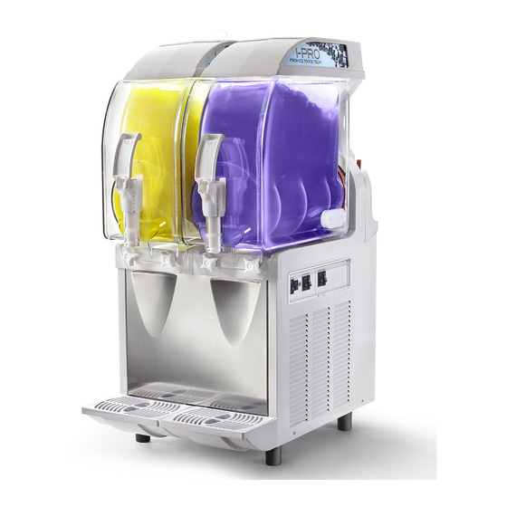
GRANITAMASCHINE
SLUSH MACHINE
APPAREIL À GRANITÉS
IPro
R290
Achtung: Brandgefahr - R290
Attention: risk of fire – R290
Attention: risque d'incendie - R290
GEBRAUCHS- UND WARTUNGSANLEITUNG
OPERATOR'S MANUAL
NOTICE D'UTILISATION ET D'ENTRETIEN
Ausgabedatum: October, 2018
DEUTSCH
ENGLISH
FRANÇAIS
Revision: 2
SEITE 2
PAGE 24
PAGE 47
Seite : 1/76
Advertisement
Table of Contents

Summary of Contents for SPM IPro R290
- Page 1 GRANITAMASCHINE SLUSH MACHINE APPAREIL À GRANITÉS IPro R290 Achtung: Brandgefahr - R290 Attention: risk of fire – R290 Attention: risque d'incendie - R290 DEUTSCH SEITE 2 ENGLISH PAGE 24 GEBRAUCHS- UND WARTUNGSANLEITUNG FRANÇAIS PAGE 47 OPERATOR’S MANUAL NOTICE D'UTILISATION ET D'ENTRETIEN Ausgabedatum: October, 2018 Revision: 2 Seite : 1/76...
-
Page 2: Table Of Contents
INDEX 1. IMPORTANT WARNINGS AND ADVICES ..............26 2. EQUIPMENT KIT ........26 3. TRANPORT TIPS ........26 4. LIFTING TIPS ..........26 5. TECHNICAL SPECIFICATIONS ....27 6. POSITIONING ..........28 7. CONNECTION TO THE POWER SUPPLY MAINS ............29 8. START-UP PROCEDURES .......30 9. ELECTRONIC CONTROL BOARD ..31 Manual mode .......... -
Page 3: Equipment Kit
1. IMPORTANT WARNINGS AND 2. EQUIPMENT KIT ADVICES In the packaging of this equipment you will find This installation and operation manual is also: an integral part of the equipment and must - operator’s manual, be kept for future consultation. - 1 tube of Vaseline grease lubricant to be used Unless otherwise stated, this manual is for machine maintenance;... -
Page 4: Technical Specifications
The machine must be stored in a dry place with Noise emissions temperatures from 0°C to 40 °C. No more than 2 machines should be stacked on top of each The continuous, equivalent, weighted level of other, taking care to maintain the vertical acoustic pressure is below 70 dB. -
Page 5: Positioning
6. POSITIONING FOR SERVICEMAN ONLY The installation and subsequent servicing operations must be carried out by skilled members who have been trained to use the device and in compliance with the regulations in force. a) Remove the packing (fig.1), preserve it in order to reuse for winter storage and make sure the machine is in perfect condition. - Page 6 7. CONNECTION POWER SUPPLY MAINS FOR SERVICEMAN ONLY Before fitting the plug in the power supply socket, your safety, already mentioned in the previous paragraph, please read the following precautions. machine’s electrical safety only guaranteed when it is connected to a suitable earth system, structured as provided by the national safety...
-
Page 7: Start-Up Procedures
8. START-UP PROCEDURES !IMPORTANT! BEFORE STARTING THE MACHINE, CARRY OUT THE CLEANING AND SANITISING PROCEDURES DESCRIBED IN CHAPTER 11. - Dilute and mix the product in a separate container according to the manufacturer’s instructions (see fig.4); never pour dry powder, crystals, or concentrate into a dry bowl. -
Page 8: Electronic Control Board
9. ELECTRONIC CONTROL BOARD Manual mode After connecting the unit plug with the electricity main, the unit is ready to be switched on. The control panel appears like the one in figure 8. Touching the ON/OFF symbol with a finger on the capacitive display, it will be completely Fig. -
Page 9: Automatic Mode
Automatic mode Setting mode Pushing the AUTO button the unit will start In order to activate the setting mode it is working in the automatic mode with the set necessary to put the finger on the ON/OFF parameters; this mean that the unit will button for 6/7 seconds;... - Page 10 Once entered the setting mode i twill be NOTE: once the week time table has been possible to set the following parameters: set, the unit will automatically maintain it. TIME, DAY AND TIME MODE NOTE: when the AUTO button is switched on, the automatic mode parameters are Once entered the setting mode the first active and the FREEZE and CHILL buttons...
- Page 11 “FILTER CLEANING” Alarm A filter cleaning alarm will activate when the unit is running hot due to insufficient internal air circulation. When this occurs the FILTER message will start blinking on the capacitive display as shown in picture 10. To determine the condition that caused the alarm, see list of conditions below: ...
-
Page 12: Mechanical Control Board
10. MECHANICAL CONTROL BOARD c) The (E) switch controls the covers’ LED lights. a) Activate the general switch (D); !CAUTION! IPRO is equipped with an insulated bowl b) Each bowl is controlled by two switches which that will preserve the product temperature are activated as follows: for many hours so once it will be necessary to operate in defrost/chill mode, we... -
Page 13: Operating Instructions
11. OPERATING INSTRUCTIONS a) To dispense the product, position the cup under the tap and pull the dispensing lever (see figure 12). Fig. 12 b) Adjusting the consistency: to alter the consistency of the product, turn the screws located on the back of the machine in the following way: clockwise to make the product less dense, counter clockwise to make the product denser (see figure 13). -
Page 14: Daily Cleaning And Sanitizing Procedures
12. DAILY CLEANING AND SANITIZING PROCEDURES In order to maintain the machine in like-new operating condition and to respect current regulations, it’s absolutely necessary to frequently and carefully perform the cleaning and sanitizing operations as described below. In case of prolonged shutdown (winter storage), the machine must be disassembled, washed and sanitized according to the instructions in this manual before start-up to ensure the best... - Page 15 - Empty the bowl of any remaining product. - After unlocking the main cover with its key, remove it. - Fill the bowl with lukewarm water to help melt off any sugar residuals and drain this water before proceeding with the next step. Caution To avoid electrical shock or contact with moving parts, before proceeding with the...
- Page 16 - Unscrew the securing bolt (S) in the direction of the arrow (threading on the left), pull off of the mixing unit (U), and remove the sealing washers (X) and (T) (see figure 18). Caution Avoid the use of abrasive cleaners which can damage the finish.
- Page 17 Once performed all these cleaning and sanitizing procedures, it’s possible to reassemble all the components. The correct assembly of the device is essential to prevent leakage of product and damage of the machine. To assemble the machine you will need an approved lubricant (such as Vaseline). Make sure all parts have been washed and sanitized before assembling.
- Page 18 - Reassemble the parts of the dispensing tap, making sure that the gaskets (J) are lubricated with Vaseline grease so that the tap slides smoothly back into its fixed position, until it’s completely inserted (see figure 24). !Important! The not perfect sliding of the tap compromises its own seal.
- Page 19 SANITIZING Whenever the machine has remained unused for some days after been cleaned and sanitized as described in the chapter 11, the sanitizing procedures described below must be performed just prior to start-up the machine. - Remove the main cover and the secondary transparent one.
-
Page 20: Special Maintentance
13. SPECIAL MAINTENTANCE Caution Before proceeding with any maintenance operation, it is compulsory to switch off the machine and unplug it from the mains. Condenser cleaning In order to guarantee good cooling system performance, condenser must well cleaned every month. How to reach it: Fig. -
Page 21: Control And Replacement Of Seals
Control and replacement of seals 14. DISCLAIMER BOWL GASKET (LOCATED AT THE REAR OF The manufacturer declines all responsibility for BOWL) any damage that directly or indirectly might be Replace it every 12 months according to the brought on to people, things, animals, as a conditions of use and level of maintenance. -
Page 22: Troubleshooting Guide
15. TROUBLESHOOTING GUIDE NOTE: the following procedures must be performed by a qualified service technician. Problem Possible cause Solution The machine does not cool, space around machine Allow at least 20cm between the or cools only partially and inadequate for ventilation machine and anything next to it;... - Page 23 message appears cleaned instructions capacitive touch panel The unit is positioned too close to a wall Reposition unit to maximize or other object restricting air flow and ventilation space (see causing the machine to run at a higher installation figures) temperature ...
Need help?
Do you have a question about the IPro R290 and is the answer not in the manual?
Questions and answers