
Summary of Contents for Valloy Incorporation DUOBLADE F
- Page 1 DUOBLADE F Digital Die Cutting System User Guide v.2.1.1. Please read this manual carefully before using the device Valloy Incorporation 2018 June 1 Pag 1...
- Page 2 Copyright statement © 2018 VALLOY Inc., This document, attachments, and information contained herein are the confidential and proprietary property of VALLOY Inc. and their suppliers. As such, this document, attached files, and information contained herein are subject to all nondisclosure and proprietary information agreements currently in effect with your organization.
-
Page 3: Table Of Contents
Table of Contents Table of Contents Chapter 1. Safety Matters 1-1: Safety Issues to pay attention 1-2: Warning Label Description 1-3: Safety Instructions Chapter 2. Transportation and Installation Chapter 3. System Introduction 3-1: Packing List 3-2: System Parameters 3-3: Parts Description Chapter 4. -
Page 4: Chapter 1. Safety Matters
Chapter 1. Safety Issue 1-1 Safety Issues to pay attention 1. The basic guidelines for safe operation, the following four conditions must be observed by the operator: (1) The machine should be operated or maintained by trained technician only. (2) Read this user manual carefully and understand the contents thoroughly before operation. (3) For convenience, put this user manual at easy access, near by the machine. - Page 5 (2) Do not remove or change the position of the interlock mechanism. (3) Do not touch the switch with wet hands. (4) Do not place any part of the body on the moving part of the machine or beside it. (5) Keep your hair away from machine moving parts.
-
Page 6: 1-2: Warning Label Description
1-2 Warning Label Description Keep door closed. Rolling gears, chains, belts and pulleys inside which may cause personal injury. Be away from rolling parts like rollers or belts of running machine, which may cause personal injury Do not touch the machine by hands during machine is running. -
Page 7: 1-3: Safety Instructions
1-3 Safety Instructions Do not touch the knife tip with your finger. This can cause your finger to be injured. Do not damage or modify/change original power cable. Do not make the power cable excessively bent, pulled, bundled, or pressed under heavy objects. This will damage the power supply, resulting in electric shock or fire. -
Page 8: Chapter 2. Transportation And Installation
Chapter II Transportation and Installation 2-1 Crate handling When transporting wooden boxes, use a forklift with a carrying capacity of 500kg or more. 2-2 Packing and Unpacking Packing : When packing, fix the four wheels of the machine first, and then lower the pads to keep the balance and prevent movement or sliding. -
Page 9: Chapter 3. System Introduction
Power cable Keys Magnetic guide plates Software and Video Manual CD + USB Lock 3-2 System parameters Machine name DuoBlade F Digital die cutting machine (DB340F) Maximum paper width 340mm Maximum paper length 570mm Maximum label width 340mm Minimum label width... -
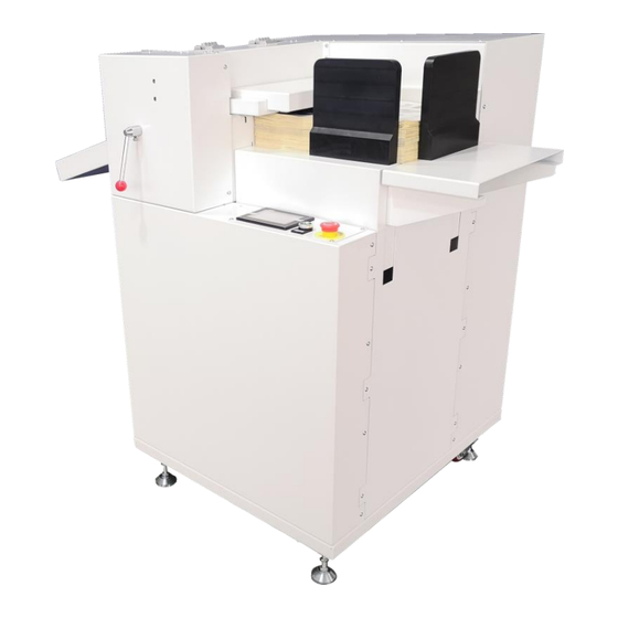
Page 10: 3-3: Parts Description
3-3 DuoBlade F (DB340F) Digital Die Cuter Parts Description (Structural components schematic) < PICTURE 3-1 > < PICTURE 3-2 > Pag 10... - Page 11 description description Emergency stop switch control panel Pressing lever Feed elevator Cardboard Suction suction module Double knife assembly, slider assembly Data transmission port Main power switch main power port Casters Paper bucket Marking sensor Pag 11...
-
Page 12: Chapter 4. Preparation
Chapter IV Preparation 4-1 Mark Sensor Setting Mark sensor < PICTURE 4-1 > When installing the label media, make sure that the sensor is properly installed and the sensitivity of the sensor is well-adjusted to recognize the mark correctly. Make sure that the green indicator light is on when the sensor is looking at the blank white space, and the yellow and green indicator lights are on when the sensor is looking at the black mark. -
Page 13: 4-2: Cutting Head Installation
If you are using dark colored media with light colored mark, set the D/L switch to "D" (dark) position. Move the sensor’s focus on the light-colored mark first. Rotate the adjusting knob to starting position of "+" (the right limit position). Turn the adjusting knob in the "-" direction until the yellow LED goes out. Keep this as position 1. - Page 14 2. Replace cutting blade See Figure 4-4~4-5 and carefully hold the blade to avoid cutting yourself < PICTURE 4-4 > < PICTURE 4-5 > Step 1 - Rotate the blade length adjustment knob to retract the blade back to the knife holder as shown in Figure 4-6.
- Page 15 < PICTURE 4-7> Step 2 - First align the tip of the cutting tip with the tip of the cutting tip, and then extend the blade from this position depending on the thickness of the media to be cut. Step 3 - Assuming the face paper thickness is "t" (as shown in Figs. 4-8), the blade length "l" should be equal to or slightly longer than "t".
-
Page 16: 4-3: Material Preparation
4-3 Material Preparation Sort out material sheets evenly and place on the lifting platform of the die-cutting machine. The black mark of the material needs to be on the left side. Fix the upper left corner of the material to be aligned with the upper left corner of the machine and use 2 magnetic plates to fix the other two sides. -
Page 17: Chapter 5. System Operation Instructions
Chapter 5. System Operation Instructions 5-1 Panel operation instructions 1. Power button: The machine power is on. 2. Emergency stop button: All motors stop working and only system work. After starting the system, tap the screen to enter the main program, the machine will automatically reset, and click on the numerical display area to change the value. - Page 18 Parameter Parameter Parameter Description On-screen display Name Setting Range X1 vert. Based on the origin, change the X direction -10000~10000 vertical angle (unit 0.1% degree) for single mark track mode -10000 10000 Y1 vert. Based on the origin, change the Y direction -10000~10000 10000 vertical angle (unit 0.1% degree) for single mark...
- Page 19 Parameter Parameter Parameter Description On-screen display Name Setting Range Cut Ad. Change the radius value of knife tip turning at corner. The 0~100 unit is 0.025mm. Note: when you use software settings instead, please use 0 or near 0 value. When you change from Default value, it adjusts gap between heads Cut P.
- Page 20 Parameter Description Parameter Parameter On-screen display Name Setting Range Blade P.1 The larger the setting, the greater the knife pressure, unit: gf/cm2 400~1000 The larger the setting, the greater the knife pressure, unit: gf/cm2 Blade P.2 400~1000 Speed of heads when moving manually (e.g. finding marks) HS / LS High speed/low speed...
- Page 21 Duo-Blade F provides fully adjustable and controllable parameters to utilize the functionality of the machine in maximum level. Duo-Blade F can meet the requirements of beginners and advanced users together. Some of parameters can be complicated to understand by short explanation in above table. Some more explanations and illustrations are provided in following for better understanding.
- Page 22 Position X Cut Ad and Y Cut Ad adjust position of image in X direction and Y direction separately. Refer to below picture for better understanding. Corner cutting control “Rotary Rad (Turn Radius)” parameter means corner moving radius. Knife has a cutting tip with a certain angle, a little apart from the center of cutting knife holder.
-
Page 23: 5-2: Software Installation
5-2 Software Installation DUO-BLADE software is proprietary operating software for Duo-Blade digital die-cutting machine only. It imports DXF, PLT file from design programs like Adobe Illustrator or Corel Draw and send the data to the machine with proper settings through USB or TCP/IP network. Learn more details about it in this chapter. Overall. -
Page 24: 5-3: File Design
File Design First of all, please do not prepare design files for printing and cutting separately. It can cause registration problem if you prepare them separately. Prepare single design for printing and add cutting contours for cutting. Make contours invisible during printing and delete printable designs during exporting of cutting file. Corel Draw In case of Corel Draw, it allows saving as HPGL1 PLT file. - Page 25 Adobe Illustrator We recommend to prepare the design to have black marks in left side (feeding direction is right to left) before saving as <Picture 5.1.>. < PICTURE 5.1. > Because of feeding direction and easy understanding. < PICTURE 5.2. > [How to put Black Marks?] It is required to put 2 black marks side by side with the design.
- Page 26 [Set X, Y position 0,0 for left top of ‘Artboard’ position] Please set X, Y position 0,0 for left top of ‘artboard’ position in illustrator. (Refer to <Picture 5.5.>) It is very important to set cutting area on the machine. If you set wrong position, cutting head will not be able to correct cutting position.
- Page 27 We recommend the color of BM is pure Black (K=100) and no ‘out-line’ <PICTURE 5.8.> [Black Mark order and assign Label cutting order] One black Mark. Even though you use one black Mark, please design 2 black marks in the design for future use. Caution.
- Page 28 <PICTURE 5.11.> Caution. Cutting software doesn’t accept the black mark in other position like <PICTURE 5.12> <PICTURE 5.12> [Set label cutting order on illustrator] After set black order Objects in design file needs to have proper order, just like the sequence of black marks.
- Page 29 < PICTURE 5.13> [Additional recommendation] The gap between label and end-margin. We recommend to have max. 10mm margin in the end of job – distance (3) in below <Picture 5.14>. If distance (3) is larger than 10mm, next mark cannot be sensed correctly. Gaps of (1) and (2) between labels have no limitation, but recommended gap is 3mm ~ 5mm.
- Page 30 < PICTURE 5.15 > Do not use any ‘Grouping’, ‘Compound Path’ or ‘Clipping Mask’ function in illustrator. These functions will cause unknown bugs on AI2PLT converting software. Use ‘Join’ to combine paths of different objects. < PICTURE 5.16 > Pag 30...
- Page 31 Keep one Layer per one cutting file. Please do not put more than 2 Layer in one cutting file. 1 cutting file only has 1 layer. < PICTURE 5.17 > [How to Save on illustrator] If you make or revise cutting file successfully in illustrator, then please save as *.ai file. without ‘Use Compression’...
-
Page 32: 5-4: Converting Cutting File Format 'Ai2Plt
5-4 Converting cutting file format by ‘AI2PLT’ tools If you make cutting file successfully in illustrator, now it’s time to convert the file from *.ai to *.plt format. (F.Y.I. Valloy cutting software can support *.plt or *.dxf format.) < PICTURE 5.19 > 1. -
Page 33: 5-5: How To Connect The Machine With Pc
5-5 How to connect the machine with your PC 1. Data Transfer Mode - NETWORK Set Transfer M. as ‘Network’, among ‘UART’, ‘Network’, and ‘USB’ < PICTURE 5.20 > 2. Set Network P. as ‘8088’. < PICTURE 5.21 > 3. Set Network ID and Target ID. (If you don’t know the IP address, please ask to network manager. ‘Network ID’... - Page 34 < PICTURE 5.23 > 2. Data Transfer Mode – USB. 1. Insert USB storage. < PICTURE 5.24 > 2. Set Transfer M. as ‘USB’, among ‘UART’, ‘Network’, and ‘USB’. < PICTURE 5.25 > 3. Click ‘Read USB Disk’. Then you can see cutting files in your USB. Please click and start. Caution 1.
-
Page 35: 5-6: Duo-Blade Software Operation
5-6 DUO-BLADE software operation Run DUO-BLADE software by double clicking the short cut icon or execution file. < PICTURE 5.26 > Summary of software menu Please refer to below table for overview of software menu. menu sub-menu function REMARK Icon access open Open *.plt, *.dxf file... - Page 36 File opening Open sample files provided together with the program as shown in <Picture 5.27>. Click “file“ menu and select “Open” or click OPEN icon to choose a specific PLT or DXF file to open. < PICTURE 5.27 > < PICTURE 5.28 > Color Settings and Object Assignment Setup colors for marks and cutting lines separately.
- Page 37 < PICTURE 5.29 > < PICTURE 5.30 > You need to assign marks as Draw and cutting lines as Ncut. Draw component means reference object without requiring cutting like black marks, where PEN color will be applied. Ncut component means actual cutting lines where Cutting color will be applied.
- Page 38 < PICTURE 5.31. > Parameter Settings Click menu > Settings > “Set para” or click [Set Para] icon in the main program GUI to access to parameter settings window as shown in <Picture 5.32> < PICTURE 5.32 > Parameter settings window has 3 tabs. Click “Target Device” tab and uncheck ‘variable’ and click EDIT button.
- Page 39 We setup all the parameters in Output Port tab already. Go to “Send Mode” tab and setup parameters. Default values are shown in <Picture 5.34> and you do not need to edit them in general cases. < PICTURE 5.34 > Output type : Use ‘Original File Type’...
- Page 40 < PICTURE 5.36 > Adjustment Starting Point You can select starting point of cutting in each object. Adjust of starting point is important for some cases, because the direction of knife tip on starting point of new object is depending on ending point of the previous object.
- Page 41 In starting point setup mode, display will be shown differently as below <Picture 5.39> by indicating current starting points and directions for each object. < PICTURE 5.39 > Click any point of objects to change the starting position and click OK button in right end of the GUI. If you select ‘Drop point knife set’...
- Page 42 FEEDING DIRECTION < PICTURE 5.41 > Language and About Select Language in the menu to choose your preferred language for main GUI menu like <Picture 5.42>. Select Help > About in the menu to find out copy right information and the current version information of DuoBlade Die-Cut software like <Picture 5.43>.
- Page 43 Job Data Sending When everything is ready, click “Print” icon or select file > Print menu as <Picture 5.45> Duo-Blade F’s LCD panel will display “Receiving data” message. After receiving, machine will be ready to cut as <Picture 5.46>. < PICTURE 5.45 > <...
- Page 44 Double Head Cutting Operation You do not need to make the file which only for using double blade separately. When you cut all labels by using single blade, you need to choose all labels to cut and the machine should be set only ‘Cutter 1’...
- Page 45 < PICTURE 5.49 > 1. Arc Com :If label has round corner, set the value in the Red frame as below. This is the same with Rotady Rad (Turn Radius) parameter in machine LCD. You can use the same feature in the software and apply selectively to round corner only.
- Page 46 3. Arc Com + Cor Com : If there are round corner and right corner together in the label, set the value in the Red frame as below. After selecting, click and then click < PICTURE 5.52 > 4. Up Com :If starting point and end point are not connected, please set Up Com value in the Red Frame, to cut longer till raising the head up.
- Page 47 5. Down Com If starting point and end point are not connected, you can also set Down Com value in the Red Frame, to cut longer by starting the cutting earlier. After selecting, click and then click < PICTURE 5.55 > Pag 47...
-
Page 48: Chapter 6. Equipment Maintenance
Chapter 6. Equipment Maintenance 6-1 Maintenance General mechanical inspections are done at least once a day. If there is dust or debris from the workpieces, use alcohol or gasoline to clean the residual glue on the knife seat and on the platform. General cleaning is a must, and the frequency of cleaning depends on the material being processed. -
Page 49: 6-2: Troubleshooting
6-2 Troubleshooting Panel Error Issue Solution Message Issue Message Self-checking fail Panel and motherboard Turn off the power and restart communication error If error continues, contact VALLOY support center. Resetting Reset sensor failure Reset sensor is installed in the end of head scanning line. -
Page 50: Chapter 7. Equipment Warranty
Chapter 7. Equipment Warranty VALLOY Incorporation (hereinafter referred to as "Valloy") will provide reasonable monitoring and preventive measures to ensure that users use materials of good quality. In any case, Valloy’s liability is limited to the contract price of the product and is not responsible for the excess.
Need help?
Do you have a question about the DUOBLADE F and is the answer not in the manual?
Questions and answers