Table of Contents
Advertisement
SOUTHERN AVIONICS COMPANY
MANUFACTURERS OF LOW FREQUENCY RADIOBEACONS AND ASSOCIATED PRODUCTS
Model SA100 Dual/IP66 Remote EC
Non-Directional Beacon Transmitter NDB
Manual #SD405082
Revision F
Printed
September 30, 2008
Box 5345 • Beaumont • Texas • 77726-5345 • USA • Phone (409) 842-1717 • Fax (409) 842-2987 • Email
sales@southernavionics.com
www.southernavionics.com
Advertisement
Table of Contents
Troubleshooting

Summary of Contents for SAC SA100
- Page 1 SOUTHERN AVIONICS COMPANY MANUFACTURERS OF LOW FREQUENCY RADIOBEACONS AND ASSOCIATED PRODUCTS Model SA100 Dual/IP66 Remote EC Non-Directional Beacon Transmitter NDB Manual #SD405082 Revision F Printed September 30, 2008 Box 5345 • Beaumont • Texas • 77726-5345 • USA • Phone (409) 842-1717 • Fax (409) 842-2987 • Email sales@southernavionics.com...
- Page 2 SOUTHERN AVIONICS COMPANY MANUFACTURERS OF LOW FREQUENCY RADIOBEACONS AND ASSOCIATED PRODUCTS This page intentionally left blank. Box 5345 • Beaumont • Texas • 77726-5345 • USA • Phone (409) 842-1717 • Fax (409) 842-2987 • Email sales@southernavionics.com www.southernavionics.com...
- Page 3 SAC in writing for use with SAC equipment. ALL IMPLIED WARRANTIES EXISTING UNDER THE LAW ARE HEREBY EXPRESSLY NEGATED;...
- Page 4 SOUTHERN AVIONICS COMPANY MANUFACTURERS OF LOW FREQUENCY RADIOBEACONS AND ASSOCIATED PRODUCTS CONSEQUENTIAL OR SPECIAL DAMAGES RESULTING FROM ANY DEFECT IN THE GOODS OR ANY FAILURE OF THE GOODS TO CONFORM WITH THIS WARRANTY OR ANY IMPLIED WARRANTY EXISTING AND APPLICABLE UNDER THE LAW (TO THE EXTENT THAT ANY SUCH IMPLIED WARRANTY BEEN...
- Page 5 Freight Costs: The Customer pays for freight costs to and from Southern Avionics Company. SAC will not be responsible for any loss or damage of any items in transit either to or from SAC. Expiration of Support: SAC supports all items manufactured by SAC for no less than ten (10) years from date of original purchase.
- Page 6 SOUTHERN AVIONICS COMPANY MANUFACTURERS OF LOW FREQUENCY RADIOBEACONS AND ASSOCIATED PRODUCTS This page intentionally left blank. Box 5345 • Beaumont • Texas • 77726-5345 • USA • Phone (409) 842-1717 • Fax (409) 842-2987 • Email sales@southernavionics.com www.southernavionics.com...
- Page 7 SOUTHERN AVIONICS COMPANY MANUFACTURERS OF LOW FREQUENCY RADIOBEACONS AND ASSOCIATED PRODUCTS ELECTROMAGNETIC COMPATIBILITY (EMC) This apparatus is intended for use in a professional environment by personnel fully conversant with it’s use and application. It should not be operated in close proximity to domestic electrical equipment.
- Page 8 SOUTHERN AVIONICS COMPANY MANUFACTURERS OF LOW FREQUENCY RADIOBEACONS AND ASSOCIATED PRODUCTS This page intentionally left blank. Box 5345 • Beaumont • Texas • 77726-5345 • USA • Phone (409) 842-1717 • Fax (409) 842-2987 • Email sales@southernavionics.com www.southernavionics.com...
- Page 9 SOUTHERN AVIONICS COMPANY MANUFACTURERS OF LOW FREQUENCY RADIOBEACONS AND ASSOCIATED PRODUCTS Box 5345 • Beaumont • Texas • 77726-5345 • USA • Phone (409) 842-1717 • Fax (409) 842-2987 • Email sales@southernavionics.com www.southernavionics.com...
- Page 10 SOUTHERN AVIONICS COMPANY MANUFACTURERS OF LOW FREQUENCY RADIOBEACONS AND ASSOCIATED PRODUCTS This page intentionally left blank. Box 5345 • Beaumont • Texas • 77726-5345 • USA • Phone (409) 842-1717 • Fax (409) 842-2987 • Email sales@southernavionics.com www.southernavionics.com...
- Page 11 SOUTHERN AVIONICS COMPANY MANUFACTURERS OF LOW FREQUENCY RADIOBEACONS AND ASSOCIATED PRODUCTS Become familiar with the safety symbols presented in Safety Symbols this section. These symbols will alert you to safety hazards and conditions that may result in personal injury, death, or property and equipment damage. WARNING : Electric shock hazard, high voltages capable of causing personal injury or death.
- Page 12 SOUTHERN AVIONICS COMPANY MANUFACTURERS OF LOW FREQUENCY RADIOBEACONS AND ASSOCIATED PRODUCTS This page intentionally left blank. Box 5345 • Beaumont • Texas • 77726-5345 • USA • Phone (409) 842-1717 • Fax (409) 842-2987 • Email sales@southernavionics.com www.southernavionics.com...
- Page 13 SOUTHERN AVIONICS COMPANY MANUFACTURERS OF LOW FREQUENCY RADIOBEACONS AND ASSOCIATED PRODUCTS Box 5345 • Beaumont • Texas • 77726-5345 • USA • Phone (409) 842-1717 • Fax (409) 842-2987 • Email sales@southernavionics.com www.southernavionics.com...
-
Page 14: Table Of Contents
2 Theory of Operation, Radiobeacon ............... 2-1 2.1 Functional Description: SA100 ................. 2-1 2.2 Functional Description: Autotransfer System SA Series........2-5 2.3 Detailed Circuit Analysis: SA100 ..............2-7 2.3.1 Synthesizer PWB (KWOSYN) ..............2-7 2.3.2 RF Driver ....................2-10 2.3.3 Tone Key ....................2-11 2.3.4 Audio PWB (Optional) ................ - Page 15 5 Maintenance ......................5-1 5.1 Alignment and Adjustment................5-1 5.1.1 Power Supply Check ................5-1 5.1.2 Synthesizer Adjustment................5-1 5.1.3 Tone Key PWB..................5-2 5.1.4 Keyer ......................5-2 5.1.5 Filters......................5-2 5.1.6 RF Section Check ..................5-2 viii Contents Model SA100 Dual...
- Page 16 5.1.10 DC Board....................5-5 5.1.11 DC Auto Disconnect PWB..............5-5 5.1.12 Maintenance and Troubleshooting Radiobeacon Control ...... 5-6 6 Parts List........................6-1 7 Modifications ......................7-1 7.1 EMI Filter Module....................7-1 7.2 Universal Serial Interface Adaptor ..............7-5 Model SA100 Dual Contents...
- Page 17 SOUTHERN AVIONICS COMPANY Figures Figure 1-1. Transmitter Enclosure Dimensions............. 1-4 Figure 1-2. Transmitter Portrait..................1-5 Figure 2-1. SA Dual Series Block Diagram..............2-3 Figure 2-2. Block Diagram .................... 2-6 Figure 2-3. KWOYSN Schematic ................2-8 Figure 2-4. KWOSYN PWB Diagram................2-9 Figure 2-5.
- Page 18 SOUTHERN AVIONICS COMPANY Figure 2-33. DC Power Supply PWB Diagram (Single Units)........2-48 Figure 2-34. DC Power Supply PWB Schematic (Dual Units) ........2-49 Figure 2-35. DC Power Supply PWB Diagram (Dual Units) ........2-50 Figure 2-36. DC Choke Schematic ................2-51 Figure 2-37.
- Page 19 SOUTHERN AVIONICS COMPANY matic ..........................4-9 Figure 4-2. Load Center/Battery Charger 220V Two Phase (R/M) Overall Schematic4-10 Figure 4-3. Load Center/Battery Charger 110V or 220V (R/M) Diagram....4-11 Figure 4-4. Load Center/Battery Charger 220V Two Phase (R/M) Diagram ....4-12 Figure 4-1.
- Page 20 SOUTHERN AVIONICS COMPANY Contents Model SA100 Dual...
-
Page 21: Introduction
The power portion of each transmitter consists of an output filter, a switching power amplifier, switching modulator/regulator and power supply. The SA100 Dual consists of two independent SA100 transmitters and an Automatic Transfer unit housed in a single cabinet. Model SA100 Dual... - Page 22 SOUTHERN AVIONICS COMPANY This page intentionally left blank. Introduction Model SA100 Dual...
-
Page 23: Specifications: Sa100
SOUTHERN AVIONICS COMPANY 1.2 Specifications: SA100 QUALIFICATIONS: Meets applicable requirements of ICAO, FCC, and FAA. FREQUENCY: 190-535 KHz, crystal controlled synthesizer, switch selectable in 500 Hz increments, stability better than .005% (-40 degrees C to +70 degrees C). POWER OUTPUT: Carrier power into 50 Ohms continuously adjustable 25 to 100 Watts, (100- 400 W PEP). -
Page 24: Figure 1-1. Transmitter Enclosure Dimensions
SOUTHERN AVIONICS COMPANY Figure 1-1. Transmitter Enclosure Dimensions Introduction Model SA100 Dual... -
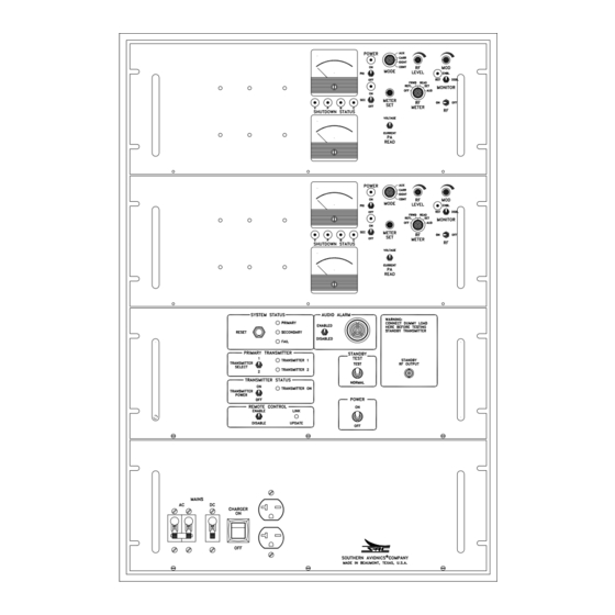
Page 25: Figure 1-2. Transmitter Portrait
SOUTHERN AVIONICS COMPANY Figure 1-2. Transmitter Portrait Model SA100 Dual Introduction... - Page 26 SOUTHERN AVIONICS COMPANY This page intentionally left blank. Introduction Model SA100 Dual...
-
Page 27: General Description: Sa Radiobeacon Control System
Control status in the Local Radiobeacon Control Panel is maintained by latching control circuits to insure operation during loss of the control data link and to insure automatic resumption of operation following power failures. Model SA100 Dual Introduction... - Page 28 SOUTHERN AVIONICS COMPANY This page intentionally left blank. Introduction Model SA100 Dual...
-
Page 29: Specifications: Automatic Transfer Unit Sa Series
INDICATORS: TRANSMITTER ON, AC POWER present (at transmitter site), PRIMARY TRANSMITTER (TRANSMITTER 1/TRANSMITTER 2) SYSTEM STATUS (PRIMARY, SECONDARY, FAIL), REMOTE CONTROL ENABLE, REMOTE CONTROL LINK UPDATE. VOICE indicates handset activated. DATA indicates handset switched off. POWER: 115/230 VAC ±20% 50/60 Hz 5VA. Model SA100 Dual Introduction... -
Page 30: Control Link Specifications
3 mA. NOTE: Measurement made with panel power OFF at end to be measured, to disable modem carrier. LINE IMPEDANCE: 600 ohm, balanced, (300 ohm minimum, 900 ohm maximum). Notice If modem is not used, serial data link wire will be 2 conductor 22 AWG shielded. 1-10 Introduction Model SA100 Dual... -
Page 31: Theory Of Operation, Radiobeacon
SOUTHERN AVIONICS COMPANY 2 Theory of Operation, Radiobeacon 2.1 Functional Description: SA100 Synthesizer: The RF signal is generated on the KWOSYN PWB by a voltage controlled LC oscillator operating at twice the RF frequency. This signal is divided to produce a 1 KHz signal that is fed to a phase locked loop (PLL) and compared with a 1 KHz signal produced by a divided 4.096 MHz crystal oscillator signal. - Page 32 AC and DC supplies, the optional batteries supply power without interruption whenever AC power is lost. Battery Charger (optional): The optional battery charger system automatically charges the batteries in two modes, fast charge and float mode depending on the battery condition. Theory of Operation, Radiobeacon Model SA100 Dual...
-
Page 33: Figure 2-1. Sa Dual Series Block Diagram
SOUTHERN AVIONICS COMPANY Figure 2-1. SA Dual Series Block Diagram Model SA100 Dual Theory of Operation, Radiobeacon... - Page 34 SOUTHERN AVIONICS COMPANY This page intentionally left blank. Theory of Operation, Radiobeacon Model SA100 Dual...
-
Page 35: Functional Description: Autotransfer System Sa Series
2.2 Functional Description: Autotransfer System SA Series The SAC Radiobeacon Control Systems is composed of a Local Radiobeacon Control Panel and one or more optional Remote Control Panels. Primary AC power and auxiliary battery power is attached to terminal blocks on the Local Radiobeacon Control Panel relay assembly. -
Page 36: Figure 2-2. Block Diagram
SOUTHERN AVIONICS COMPANY Figure 2-2. Block Diagram Theory of Operation, Radiobeacon Model SA100 Dual... -
Page 37: Detailed Circuit Analysis: Sa100
SOUTHERN AVIONICS COMPANY 2.3 Detailed Circuit Analysis: SA100 2.3.1 Synthesizer PWB (KWOSYN) Q1 and its associated circuitry form a voltage controlled Colpitts oscillator with frequency variable from two times 190 KHz to two times 535 KHz. With L2 in the circuit, the frequency can be tuned... -
Page 38: Figure 2-3. Kwoysn Schematic
SOUTHERN AVIONICS COMPANY Figure 2-3. KWOYSN Schematic Theory of Operation, Radiobeacon Model SA100 Dual... -
Page 39: Figure 2-4. Kwosyn Pwb Diagram
SOUTHERN AVIONICS COMPANY Figure 2-4. KWOSYN PWB Diagram Model SA100 Dual Theory of Operation, Radiobeacon... -
Page 40: Rf Driver
Amplifier (SPA) board(s) at pin 1. For a schematic of the RF Driver, see drawing "SA Series Transmitter Overall Schematic." For a Diagram of the RF Driver, see drawing "SA Series Exciter Control Motherboard Diagram." 2-10 Theory of Operation, Radiobeacon Model SA100 Dual... -
Page 41: Tone Key
18. To select 1020 Hz or 400 Hz tone, install the appropriate jumpers that correspond with the desired frequency. See figure "Tone Key PWB Schematic" and "Tone Key PWB Diagram." Provisions are available for operating the transmitter in the optional emission modes of CW, MCW, KMCW and PTT. Model SA100 Dual Theory of Operation, Radiobeacon 2-11... -
Page 42: Figure 2-5. Tone Key Schematic
SOUTHERN AVIONICS COMPANY Figure 2-5. Tone Key Schematic 2-12 Theory of Operation, Radiobeacon Model SA100 Dual... -
Page 43: Figure 2-6. Tone Key Pwb Diagram
SOUTHERN AVIONICS COMPANY Figure 2-6. Tone Key PWB Diagram Model SA100 Dual Theory of Operation, Radiobeacon 2-13... -
Page 44: Audio Pwb (Optional)
R34 according to the following table. Time | Value | Comments --------------------------------- 5 sec | 470K | Default 8 sec | 820K | 11 sec| 1.2M | 2-14 Theory of Operation, Radiobeacon Model SA100 Dual... -
Page 45: Figure 2-7. Audio Pwb Schematic
SOUTHERN AVIONICS COMPANY Figure 2-7. Audio PWB Schematic Model SA100 Dual Theory of Operation, Radiobeacon 2-15... -
Page 46: Figure 2-8. Audio Pwb Diagram
SOUTHERN AVIONICS COMPANY Figure 2-8. Audio PWB Diagram 2-16 Theory of Operation, Radiobeacon Model SA100 Dual... -
Page 47: Modulator Driver
RF Mother board(s) and connected to the pin 9 input of the Modulator (DMOD) board(s). For a schematic of the Modulator Driver see drawing "SA Series Overall Schematic." For a diagram of the Modulator Driver, see drawing "SA Series Exciter Control Motherboard Diagram." Model SA100 Dual Theory of Operation, Radiobeacon 2-17... -
Page 48: Figure 2-9. Actrl Schematic
SOUTHERN AVIONICS COMPANY Figure 2-9. ACTRL Schematic 2-18 Theory of Operation, Radiobeacon Model SA100 Dual... -
Page 49: Figure 2-10. Actrl Diagram
SOUTHERN AVIONICS COMPANY Figure 2-10. ACTRL Diagram Model SA100 Dual Theory of Operation, Radiobeacon 2-19... -
Page 50: Keyer
Extension (pin 22) of the first PWB, doubling the length of the serial connected shift register and doubling the number of possible bits in the code sequence. U20 and U21 are level shifters added to maintain 12V interboard logic levels. 2-20 Theory of Operation, Radiobeacon Model SA100 Dual... -
Page 51: Figure 2-11. Keyer Code Schematic
SOUTHERN AVIONICS COMPANY Figure 2-11. Keyer Code Schematic Model SA100 Dual Theory of Operation, Radiobeacon 2-21... -
Page 52: Figure 2-12. Keyer Code Pwb Diagram
SOUTHERN AVIONICS COMPANY Figure 2-12. Keyer Code PWB Diagram 2-22 Theory of Operation, Radiobeacon Model SA100 Dual... -
Page 53: Figure 2-13. Crs Sample Program
SOUTHERN AVIONICS COMPANY Figure 2-13. CRS Sample Program Model SA100 Dual Theory of Operation, Radiobeacon 2-23... -
Page 54: Figure 2-14. Coder Shift Register Schematic
SOUTHERN AVIONICS COMPANY Figure 2-14. Coder Shift Register Schematic 2-24 Theory of Operation, Radiobeacon Model SA100 Dual... -
Page 55: Figure 2-15. Coder Shift Register Pwb Diagram
SOUTHERN AVIONICS COMPANY Figure 2-15. Coder Shift Register PWB Diagram Model SA100 Dual Theory of Operation, Radiobeacon 2-25... -
Page 56: Modulator (Dmod)
DC carrier voltage for the ideal case of 100% modulation. Pin 11 of U3 and U4 is a shutdown input and is used to turn off the PA voltage when a shutdown signal is received from the MONITOR CONTROL PWB. 2-26 Theory of Operation, Radiobeacon Model SA100 Dual... -
Page 57: Figure 2-16. Dmod Schematic
SOUTHERN AVIONICS COMPANY Figure 2-16. DMOD Schematic Model SA100 Dual Theory of Operation, Radiobeacon 2-27... -
Page 58: Figure 2-17. Dmod Pwb Diagram
SOUTHERN AVIONICS COMPANY Figure 2-17. DMOD PWB Diagram 2-28 Theory of Operation, Radiobeacon Model SA100 Dual... -
Page 59: Power Amplifier
ON at the same time. The square wave output is applied to T3 where it is impedance matched to the 50 Ohm filter input. P.A. voltage and P.A. current samples from the Power Amplifier modules are routed to a front panel switch and meter. Model SA100 Dual Theory of Operation, Radiobeacon 2-29... -
Page 60: Figure 2-18. Power Amplifier Schematic
SOUTHERN AVIONICS COMPANY Figure 2-18. Power Amplifier Schematic 2-30 Theory of Operation, Radiobeacon Model SA100 Dual... -
Page 61: Figure 2-19. Power Amplifier Pwb Diagram
SOUTHERN AVIONICS COMPANY Figure 2-19. Power Amplifier PWB Diagram Model SA100 Dual Theory of Operation, Radiobeacon 2-31... -
Page 62: Figure 2-20. Filter Schematic
SOUTHERN AVIONICS COMPANY Figure 2-20. Filter Schematic Model SA100 Dual Theory of Operation, Radiobeacon 2-33... -
Page 63: Filter
650-800 KHz, 800-950 KHz, 950-1000 KHz and 1100-1250 KHz. SLP29730 is the “H” Band Filter. It’s jumpers are set for one frequency band of 1500-1800KHz. Jumper tables exist for each of the PCB’s schematics. 2-32 Theory of Operation, Radiobeacon Model SA100 Dual... -
Page 64: Figure 2-21. Filter Pwb Diagram
SOUTHERN AVIONICS COMPANY Figure 2-21. Filter PWB Diagram 2-34 Theory of Operation, Radiobeacon Model SA100 Dual... -
Page 65: Figure 2-22. Filter Pwb Jumper Detail
SOUTHERN AVIONICS COMPANY Figure 2-22. Filter PWB Jumper Detail Model SA100 Dual Theory of Operation, Radiobeacon 2-35... -
Page 66: Monitor
DMOD PWB shutdown line. This is the same as a shutdown signal and turns off the Power Amplifier high voltage. RF ON removes the 12V and connects the shutdown output from the MONITOR CTRL PWB to the DMOD PWB and DC PWB shutdown line. 2-36 Theory of Operation, Radiobeacon Model SA100 Dual... -
Page 67: Figure 2-23. Hwrf Pwb Schematic
1. THIS DRAWING NO. SEP30800, REV. F. 2. TITLE: HWRF PCB SCHEMATIC. 3. ASSEMBLY DWG. NO. SAP30800. 4. ALL RESISTORS IN OHMS, 1/4W, UNLESS NOTED. 5. ALL CAPACITORS IN uF, UNLESS NOTED. Figure 2-23. HWRF PWB Schematic Model SA100 Dual Theory of Operation, Radiobeacon 2-37... -
Page 68: Figure 2-24. Hwrf Pwb Diagram
SOUTHERN AVIONICS COMPANY Figure 2-24. HWRF PWB Diagram 2-38 Theory of Operation, Radiobeacon Model SA100 Dual... -
Page 69: Figure 2-25. Amtr1 Pwb Diagram
SOUTHERN AVIONICS COMPANY Figure 2-25. AMTR1 PWB Diagram Model SA100 Dual Theory of Operation, Radiobeacon 2-39... -
Page 70: Figure 2-26. Amtr Diagram
SOUTHERN AVIONICS COMPANY Figure 2-26. AMTR Diagram 2-40 Theory of Operation, Radiobeacon Model SA100 Dual... -
Page 71: Figure 2-27. Page 1 Monitor Schematic
SOUTHERN AVIONICS COMPANY Figure 2-27. Page 1 Monitor Schematic Model SA100 Dual Theory of Operation, Radiobeacon 2-41... -
Page 72: Figure 2-28. Page 2 Monitor Schematic
SOUTHERN AVIONICS COMPANY Figure 2-28. Page 2 Monitor Schematic 2-42 Theory of Operation, Radiobeacon Model SA100 Dual... -
Page 73: Figure 2-29. Monitor Pwb Diagram
SOUTHERN AVIONICS COMPANY Figure 2-29. Monitor PWB Diagram Model SA100 Dual Theory of Operation, Radiobeacon 2-43... -
Page 74: Figure 2-30. Sa Led Pwb Schematic
1. THIS DRAWING NO. SEP32000, REV. C. 2. TITLE: SA LED PCB SCHEMATIC. 3. ASSEMBLY DWG. NO. SAP32000. 4. ALL RESISTORS IN OHMS, 1/4W, UNLESS NOTED. Figure 2-30. SA LED PWB Schematic 2-44 Theory of Operation, Radiobeacon Model SA100 Dual... -
Page 75: Figure 2-31. Sa Led Pwb Diagram
SOUTHERN AVIONICS COMPANY Figure 2-31. SA LED PWB Diagram Model SA100 Dual Theory of Operation, Radiobeacon 2-45... -
Page 76: Dc Power Supply (Optional)
U5B goes high, and opens relay K1, which shuts down the transmitter. For Dual units or units with output power greater than 100 watts: Refer to the DC Auto Disconnect section for low battery voltage cut out. 2-46 Theory of Operation, Radiobeacon Model SA100 Dual... -
Page 77: Figure 2-32. Dc Power Supply Pwb Schematic (Single Units)
SOUTHERN AVIONICS COMPANY Figure 2-32. DC Power Supply PWB Schematic (Single Units) Model SA100 Dual Theory of Operation, Radiobeacon 2-47... -
Page 78: Figure 2-33. Dc Power Supply Pwb Diagram (Single Units)
SOUTHERN AVIONICS COMPANY Figure 2-33. DC Power Supply PWB Diagram (Single Units) 2-48 Theory of Operation, Radiobeacon Model SA100 Dual... -
Page 79: Figure 2-34. Dc Power Supply Pwb Schematic (Dual Units)
SOUTHERN AVIONICS COMPANY Figure 2-34. DC Power Supply PWB Schematic (Dual Units) Model SA100 Dual Theory of Operation, Radiobeacon 2-49... -
Page 80: Figure 2-35. Dc Power Supply Pwb Diagram (Dual Units)
SOUTHERN AVIONICS COMPANY Figure 2-35. DC Power Supply PWB Diagram (Dual Units) 2-50 Theory of Operation, Radiobeacon Model SA100 Dual... -
Page 81: Figure 2-36. Dc Choke Schematic
400V NOTES: 1. THIS DWG NO. SEP30700 REV. A. 2. TITLE: DC CHOKE PCB SCHEMATIC 3. ASSEMBLY DWG NO. SAP30700 4. ALL CAPACITORS IN uF, UNLESS NOTED. Figure 2-36. DC Choke Schematic Model SA100 Dual Theory of Operation, Radiobeacon 2-51... -
Page 82: Figure 2-37. Dchoke Pwb Diagram
SOUTHERN AVIONICS COMPANY Figure 2-37. DCHOKE PWB Diagram 2-52 Theory of Operation, Radiobeacon Model SA100 Dual... -
Page 83: Ac Power Supply (Optional)
DC high voltage supply are paralleled and connected to the Modulator High Voltage input for UPS operation. Similar connections are made with the 12V supplies so that if batteries are used, power is not interrupted upon loss of AC. Model SA100 Dual Theory of Operation, Radiobeacon 2-53... -
Page 84: Figure 2-38. Ac Power Supply Schematic
SOUTHERN AVIONICS COMPANY Figure 2-38. AC Power Supply Schematic 2-54 Theory of Operation, Radiobeacon Model SA100 Dual... -
Page 85: Figure 2-39. Ac Power Supply Diagram
SOUTHERN AVIONICS COMPANY Figure 2-39. AC Power Supply Diagram Model SA100 Dual Theory of Operation, Radiobeacon 2-55... -
Page 86: Figure 2-40. Sa Exciter Control Motherboard Schematic
SOUTHERN AVIONICS COMPANY Figure 2-40. SA Exciter Control Motherboard Schematic 2-56 Theory of Operation, Radiobeacon Model SA100 Dual... -
Page 87: Figure 2-41. Series Exciter Control Motherboard Diagram
SOUTHERN AVIONICS COMPANY Figure 2-41. Series Exciter Control Motherboard Diagram Model SA100 Dual Theory of Operation, Radiobeacon 2-57... -
Page 88: Figure 2-42. Sa Rf Motherboard Schematic
SOUTHERN AVIONICS COMPANY Figure 2-42. SA RF Motherboard Schematic 2-58 Theory of Operation, Radiobeacon Model SA100 Dual... -
Page 89: Figure 2-43. Sa Series Rf Motherboard Diagram
SOUTHERN AVIONICS COMPANY Figure 2-43. SA Series RF Motherboard Diagram Model SA100 Dual Theory of Operation, Radiobeacon 2-59... -
Page 90: Figure 2-44. Sa Series Transmitter Overall Schematic
SOUTHERN AVIONICS COMPANY Figure 2-44. SA Series Transmitter Overall Schematic 2-60 Theory of Operation, Radiobeacon Model SA100 Dual... -
Page 91: Figure 2-45. Transmitter Diagram Sa Series Rack Mount
SOUTHERN AVIONICS COMPANY Figure 2-45. Transmitter Diagram SA Series Rack Mount Model SA100 Dual Theory of Operation, Radiobeacon 2-61... -
Page 92: Detailed Circuit Analysis: Automatic Transfer System Sa Series
C SPDT relay contact set. The relay is activated in primary or secondary mode, and deactivated for fail mode or loss of operating power. The contacts are rated 1 amp at 115 VAC with a resistive load. 2-62 Theory of Operation, Radiobeacon Model SA100 Dual... - Page 93 K2 with relay contacts between pins 13 and 11 closed for transmitter OFF or contacts open for transmitter ON. Pressing the Reset pushbutton grounds reset input Pin 11 of the Autotransfer Logic Board and initiates a reset sequence. Model SA100 Dual Theory of Operation, Radiobeacon 2-63...
-
Page 94: Figure 2-46. Local Control System Overall Schematic
SOUTHERN AVIONICS COMPANY Figure 2-46. Local Control System Overall Schematic 2-64 Theory of Operation, Radiobeacon Model SA100 Dual... -
Page 95: Figure 2-47. Local Radiobeacon Control Diagram
SOUTHERN AVIONICS COMPANY Figure 2-47. Local Radiobeacon Control Diagram Model SA100 Dual Theory of Operation, Radiobeacon 2-65... -
Page 96: Figure 2-48. Sa Relay 24Vdc Pwb Schematic
SOUTHERN AVIONICS COMPANY Figure 2-48. SA Relay 24VDC PWB Schematic 2-66 Theory of Operation, Radiobeacon Model SA100 Dual... -
Page 97: Figure 2-49. Sa Relay 24Vdc Pwb Diagram
SOUTHERN AVIONICS COMPANY Figure 2-49. SA Relay 24VDC PWB Diagram Model SA100 Dual Theory of Operation, Radiobeacon 2-67... -
Page 98: Figure 2-50. Local Control Motherboard Diagram
SOUTHERN AVIONICS COMPANY Figure 2-50. Local Control Motherboard Diagram 2-68 Theory of Operation, Radiobeacon Model SA100 Dual... -
Page 99: Figure 2-51. Page 1 Autotransfer Logic Schematic
SOUTHERN AVIONICS COMPANY Figure 2-51. Page 1 Autotransfer Logic Schematic Model SA100 Dual Theory of Operation, Radiobeacon 2-69... -
Page 100: Figure 2-52. Page 2 Autotransfer Logic Schematic
SOUTHERN AVIONICS COMPANY Figure 2-52. Page 2 Autotransfer Logic Schematic 2-70 Theory of Operation, Radiobeacon Model SA100 Dual... -
Page 101: Figure 2-53. Autotransfer Logic Pwb Diagram
SOUTHERN AVIONICS COMPANY Figure 2-53. Autotransfer Logic PWB Diagram Model SA100 Dual Theory of Operation, Radiobeacon 2-71... -
Page 102: Figure 2-54. Local Transfer Indicator Pwb Diagram
SOUTHERN AVIONICS COMPANY Figure 2-54. Local Transfer Indicator PWB Diagram 2-72 Theory of Operation, Radiobeacon Model SA100 Dual... -
Page 103: Dc Auto Disconnect Pwb
SOUTHERN AVIONICS COMPANY 2.4.1.1 DC Auto Disconnect PWB The DC Auto Disconnect PWB (DCAD) is used in SAC SA Series Transmitters with power outputs greater than 100 watts and/or ALL Dual transmitter configurations when configured with DC option(s). The action of this PWB circumvents the low voltage cutout circuitry associated with the DC PWB (when required) located within each RF Group. -
Page 104: Figure 2-55. Dc Auto Disconnect
SOUTHERN AVIONICS COMPANY Figure 2-55. DC Auto Disconnect 2-74 Theory of Operation, Radiobeacon Model SA100 Dual... -
Page 105: Figure 2-56. Dc Auto Disconnect Diagram
SOUTHERN AVIONICS COMPANY Figure 2-56. DC Auto Disconnect Diagram Model SA100 Dual Theory of Operation, Radiobeacon 2-75... -
Page 106: Radiobeacon Remote Control
Transmission of the digital data stream between the Local Interface PWB and the Remote Interface PWB requires conversion of the binary bit pattern from the DC logic signals used by the transmitter and receiver integrated circuits to an audio frequency shift keyed signal suitable for 2-76 Theory of Operation, Radiobeacon Model SA100 Dual... - Page 107 A carrier detect LED is located on the Modem Board for diagnostic purposes. It will remain lit whenever a carrier of the proper frequency channel is received. Model SA100 Dual Theory of Operation, Radiobeacon 2-77...
-
Page 108: Figure 2-57. Serial Interface Pwb Schematic
SOUTHERN AVIONICS COMPANY Figure 2-57. Serial Interface PWB Schematic 2-78 Theory of Operation, Radiobeacon Model SA100 Dual... -
Page 109: Figure 2-58. Serial Interface Pwb Assembly
SOUTHERN AVIONICS COMPANY Figure 2-58. Serial Interface PWB Assembly Model SA100 Dual Theory of Operation, Radiobeacon 2-79... -
Page 110: Figure 2-59. Modem Pwb Schematic
SOUTHERN AVIONICS COMPANY Figure 2-59. Modem PWB Schematic 2-80 Theory of Operation, Radiobeacon Model SA100 Dual... -
Page 111: Figure 2-60. Modem Pwb Assembly
SOUTHERN AVIONICS COMPANY Figure 2-60. Modem PWB Assembly Model SA100 Dual Theory of Operation, Radiobeacon 2-81... -
Page 112: Figure 2-61. Remote Radiobeacon Control Panel Schematic
SOUTHERN AVIONICS COMPANY Figure 2-61. Remote Radiobeacon Control Panel Schematic 2-82 Theory of Operation, Radiobeacon Model SA100 Dual... -
Page 113: Figure 2-62. Remote Radiobeacon Control Panel Diagram
SOUTHERN AVIONICS COMPANY Figure 2-62. Remote Radiobeacon Control Panel Diagram Model SA100 Dual Theory of Operation, Radiobeacon 2-83... -
Page 114: Figure 2-63. Remote Transfer Indicator Assembly
SOUTHERN AVIONICS COMPANY Figure 2-63. Remote Transfer Indicator Assembly 2-84 Theory of Operation, Radiobeacon Model SA100 Dual... -
Page 115: Figure 2-64. Remote Control Motherboard Assembly
SOUTHERN AVIONICS COMPANY Figure 2-64. Remote Control Motherboard Assembly Model SA100 Dual Theory of Operation, Radiobeacon 2-85... - Page 116 SOUTHERN AVIONICS COMPANY This page intentionally left blank. 2-86 Theory of Operation, Radiobeacon Model SA100 Dual...
-
Page 117: Antennas
United States with one of the lower priced ADF's is from 50 to 70 miles for frequencies above 250 KHz except over low conductivity ground. SAC does not recommend this antenna for land installations at frequencies below 250 kHz. The "T"... -
Page 118: H" Antenna
"T" Antenna with a height of 80 to 85 feet has a range of 100 to 120 miles. If even more range is desired, SAC can supply "T" Antennas with heights up to 200 feet. The standard "T" is electrically very similar to a 1000 pF capacitor in series with a small resistor. -
Page 119: Figure 3-1 Antenna Reactance
SOUTHERN AVIONICS COMPANY Figure 3-1 Antenna Reactance Model SA100 Dual Antennas... - Page 120 SOUTHERN AVIONICS COMPANY This page intentionally left blank. Antennas Model SA100 Dual...
-
Page 121: Installation And Operation
Filter PWB(s) are correctly installed on the RF Motherboard(s). 4. If the optional Audio PWB is installed, connect the balanced audio line input. See figure "Transmitter Diagram SA Series." See figure "SA Relay 24VDC PWB Diagram" for dual units. Model SA100 Dual Installation and Operation... -
Page 122: Figure 4-1. Interconnecting Wire Diagram
SOUTHERN AVIONICS COMPANY Figure 4-1. Interconnecting Wire Diagram Installation and Operation Model SA100 Dual... -
Page 123: Figure 4-2. Input/Output Terminal Blocks
SOUTHERN AVIONICS COMPANY Figure 4-2. Input/Output Terminal Blocks Model SA100 Dual Installation and Operation... - Page 124 SOUTHERN AVIONICS COMPANY This page intentionally left blank. Installation and Operation Model SA100 Dual...
-
Page 125: Local Radiobeacon Control Unit
NOTE: DC current flowing in the Serial Data Link must not exceed 3 mA or saturation of the Modem coupling transformer will occur. If current exceeds 3 mA DC, install a DC blocking capacitor in the data link. Model SA100 Dual Installation and Operation... - Page 126 Primary Transmitter Select LED's on the Remote panel should change to the new transmitter. The switch can then be released. If no action occurs, refer to the maintenance and troubleshooting portion of this manual. Installation and Operation Model SA100 Dual...
-
Page 127: Load Center Battery Chargers (Optional)
Charge and Discharge Current sample resistor. This sample output is not used in all transmitter system applications. The power supply is rated at 11.1A and will foldback its output current if this limit is exceeded. Model SA100 Dual Installation and Operation... -
Page 128: Load Center/Battery Charger Installation
Ensure the AC (J3) plug is made to the three pin jack and the DC (J4) plug is connected to the two pin jack. 6. Connect AC and Batteries from source to (Enclosure TB-2). Installation and Operation Model SA100 Dual... -
Page 129: Figure 4-1. Load Center/Battery Charger 110V/220V Single Phase(R/M) Overall Sche
SOUTHERN AVIONICS COMPANY Figure 4-1. Load Center/Battery Charger 110V/220V Single Phase(R/M) Overall Schematic Model SA100 Dual Installation and Operation... - Page 130 SOUTHERN AVIONICS COMPANY Figure 4-2. Load Center/Battery Charger 220V Two Phase (R/M) Overall Schematic 4-10 Installation and Operation Model SA100 Dual...
-
Page 131: Figure 4-3. Load Center/Battery Charger 110V Or 220V (R/M) Diagram
SOUTHERN AVIONICS COMPANY Figure 4-3. Load Center/Battery Charger 110V or 220V (R/M) Diagram Model SA100 Dual Installation and Operation 4-11... -
Page 132: Figure 4-4. Load Center/Battery Charger 220V Two Phase (R/M) Diagram
SOUTHERN AVIONICS COMPANY Figure 4-4. Load Center/Battery Charger 220V Two Phase (R/M) Diagram 4-12 Installation and Operation Model SA100 Dual... -
Page 133: Alignment Procedure Rack Mount Version
14. Verify that +DC is present; a fully charged stack will yield 28.5Vcr1 or approximately 27.8 VDC. 15. Place all front panel switches and circuit breakers into the OFF position. 16. Disconnect all AC and DC input sources from the Load Center/Battery Charger. Model SA100 Dual Installation and Operation 4-13... -
Page 134: Parts List
FUSE, 15 AMP, 250V, ABC FAST ACTING TYPE 9F830030 FUSE, 3 AMP, 250V, FAST ACTING 3AG (AGC) TYPE 1R4A20A0 RES, .02 OHM, 50W, 1%, WW 9S900020 SWITCH, DPST, ROCKER, HIGH INRUSH, SNAP IN 4-14 Installation and Operation Model SA100 Dual... - Page 135 CKT BREAKER, 1 POLE, 227VAC/65V 9C350020 CKT BREAKER, 2 POLE, 227VAC/65V 9F830150 FUSE, 15 AMP, 250V, ABC FAST 9F830030 FUSE, 3 AMP, 250V 1R4A20A0 RES, .02 OHM, 50W, 1%, WW 9S900029 SWITCH, DPST, ROCKER, HIGH INRUSH Model SA100 Dual Installation and Operation 4-15...
- Page 136 9C350020 CKT BREAKER, 2 POLE, 227VAC/65 9F830150 FUSE, 15 AMP, 250V, ABC FAST 9F830030 FUSE, 3 AMP, 250V, FAST ACTING 3AG 1R4A20A0 RES, .02 OHM, 50W, 1%, WW 9S900029 SWITCH, DPST, ROCKER, HIGH 4-16 Installation and Operation Model SA100 Dual...
-
Page 137: Outdoors (Standalone) Load Center/Battery Charger Theory Of Operation4
DC bus. As the DC Main supply power to the transmitter is required to be applied and removed, CB2 is used to toggle the DC power On and Off. Model SA100 Dual Installation and Operation 4-17... - Page 138 93-132VAC for the 120V model and 187- 264VAC for the 230V single or two pole models. Changing the primary input AC supply must correspond with a change of the model of A1. 4-18 Installation and Operation Model SA100 Dual...
- Page 139 The form factor of J1 is supplied by local OEM norms, and may be substituted by the user with proper technical consideration. Model SA100 Dual Installation and Operation 4-19...
- Page 140 Some local authorities or codes require that the L2 (AC Return) circuit be uninterruptible. In this event, you are directed to ensure that F4 is jumpered out by a connection of the associated wiring from the input of F4 to J1.2. 4-20 Installation and Operation Model SA100 Dual...
-
Page 141: Figure 4-1. Load Center/Battery Charger 110Vac (Standalone) Overall Schematic
SOUTHERN AVIONICS COMPANY Figure 4-1. Load Center/Battery Charger 110VAC (Standalone) Overall Schematic Model SA100 Dual Installation and Operation 4-21... -
Page 142: Figure 4-2. Load Center/Battery Charger 110Vac Or 220Vac (Standalone) Dia
SOUTHERN AVIONICS COMPANY Figure 4-2. Load Center/Battery Charger 110VAC or 220VAC (Standalone) DIA 4-22 Installation and Operation Model SA100 Dual... -
Page 143: Alignment Procedure Standalone Version
(Adjust 22.5- 28.5) located on the Power Supply ( A1), until a voltage of 28.5 VDC is measured. 8. Place the battery charger switch (S1) to the OFF position. 9. Connect DMM, (+) to TB2.7, (-) to TB2.8 or across R1. Model SA100 Dual Installation and Operation 4-23... - Page 144 15. Remove primary AC / DC power sources. Disconnect all test equipment. 16. As necessary, disconnect all AC and DC input sources from the Load Center/Battery Charger. 17. Replace front panel. 18. Place all front panel switches and circuit breakers into the OFF position. 4-24 Installation and Operation Model SA100 Dual...
-
Page 145: Parts Lists
FUSE, 3 AMP, 250V, 3AG (AGC) FAST ACTING TYPE 9F830150 FUSE, 15 AMP, 250V, ABC FAST ACTING TYPE 1R4A20A0 RES, .02 OHM, 50W, 1%, WW 9S900029 SWITCH, DPST, ROCKER, HIGH INRUSH, SNAP IN Model SA100 Dual Installation and Operation 4-25... - Page 146 FUSE, 3 AMP, 250V, 3AG (AGC) FAST ACTING TYPE 9F830080 FUSE, 8 AMP, 250V, 3AG (AGC) FAST ACTING TYPE 1R4A20A0 RES, .02 OHM, 50W, 1%, WW 9S900029 SWITCH, DPST, ROCKER, HIGH INRUSH, SNAP IN 4-26 Installation and Operation Model SA100 Dual...
-
Page 147: Initial Transmitter Setup
9. Set RF METER switch to FRWD. 10. Set PA READ to VOLTAGE. 11. For multiple RF Groups, set PA SELECT to 1. 12. For a dual system, complete steps 1 through 11 for both transmitters. Model SA100 Dual Installation and Operation 4-27... -
Page 148: Transmitter Check
Refer to the appropriate user manual for the Coupler being installed for General descriptions, Coupler specifications, Theory of operation, Coupler setup, Antenna tune up, and Coupler parts lists. 4-28 Installation and Operation Model SA100 Dual... -
Page 149: Modulation Adjustment
Removal of the resistor silences the code tone. Install jumpers, change resistor value if desired, and complete the Code Tone Modulation Adjustment and the Voice Modulation Adjustment Sections. Model SA100 Dual Installation and Operation 4-29... -
Page 150: Code Tone Modulation Adjustment
10 percent 1.92 20 percent 2.62 Set the MODE switch to CONT, turn RF LEVEL fully CCW and turn RF OFF. Disconnect the RF cable to the Antenna Coupler. Re-apply power with RF switch. 4-30 Installation and Operation Model SA100 Dual... -
Page 151: Monitor Adjustment-Voice System
Adjust RF power from the transmitter to the desired shutdown level using RF LEVEL Control. Connect voltmeter to TP3 on Monitor PWB. Rotate R6 and R22 located on the Monitor PWB fully CCW. Model SA100 Dual Installation and Operation 4-31... -
Page 152: Automatice Shutdown Test
Connect the dummy load to the rear panel STANDBY OUTPUT connector and place the NORMAL/TEST switch in test. Transfer action is inhibited while in this mode. 4-32 Installation and Operation Model SA100 Dual... -
Page 153: Maintenance
7. For operation above 430 KHz, set the frequency to 400 KHz, S1 to the C2 position, and adjust L1 for 2V at TP2. 8. Select the assigned frequency, connect a frequency counter to TP1, and adjust C10 to the exact assigned frequency. Model SA100 Dual Maintenance... -
Page 154: Tone Key Pwb
10. Adjust RF LEVEL for rated power using the oscilloscope voltage on the dummy load. PA Voltage should not exceed 90V for all PA's. The PA voltages should be within ±10V of the Factory Acceptance Test average. Maintenance Model SA100 Dual... -
Page 155: Meter Adjustment
Input on the transmitter rear panel. Adjust R6 and/or S1 for a 70% reading on the AUDIO meter. Turn R20 and R44 fully CW. Turn RF ON. Place RF METER switch in READ. Adjust R20 CCW for 85% on the meter. Model SA100 Dual Maintenance... -
Page 156: Monitor Control Pwb
CONT. Transmitter should shut down after a time delay. Reset, place MODE switch in IDENT and reduce power to a level below the shutdown level. Transmitter should shutdown after a time delay. Reset and readjust power to desired level. Transmitter should not shutdown. Maintenance Model SA100 Dual... -
Page 157: Dc Board
Measure the battery voltage. Record this as VB. c. Calculate V13 = V12 X VB X .0526 d. Connect a voltmeter to pin 13 of U1 and adjust R4 for the voltage (V13) calculated above. Model SA100 Dual Maintenance... -
Page 158: Maintenance And Troubleshooting Radiobeacon Control
Check the Link Data Update LED's on the local and remote panels. If one or more of the Update LED's are not flashing, or are not flashing consistently, use the troubleshooting flow chart, figure "Troubleshooting Flow Chart," to determine the probable cause. Maintenance Model SA100 Dual... -
Page 159: Figure 5-1. Troubleshooting Flow Chart
SOUTHERN AVIONICS COMPANY Figure 5-1. Troubleshooting Flow Chart Model SA100 Dual Maintenance... - Page 160 SOUTHERN AVIONICS COMPANY This page intentionally left blank. Maintenance Model SA100 Dual...
-
Page 161: Parts List
Parts are listed by assembly. It is important that the entire reference designator and the part description be used when ordering parts. The serial number of the unit should also be included in any parts order. Model SA100 Dual Parts List... - Page 162 SOUTHERN AVIONICS COMPANY This page intentionally left blank. Parts List Model SA100 Dual...
- Page 163 Failure to follow these procedures may result in customer being billed for repairs on items that would normally be covered under warranty. All items returned to SAC for repair must be packaged and shipped in ESD protective bags or containers to avoid unexpected repair charges.
- Page 164 SOUTHERN AVIONICS COMPANY This page intentionally left blank. Parts List Model SA100 Dual...
- Page 165 Failure to follow these procedures may result in customer being billed for repairs on items that would normally be covered under warranty. All items returned to SAC for repair must be packaged and shipped in ESD protective bags or containers to avoid unexpected repair charges.
- Page 166 SOUTHERN AVIONICS COMPANY Parts List – SA100 REF.DES. DESCRIPTION PART NO. ANTENNA COUPLER PC-1000C ANTENNA TRANSMITTER 2 SA100 (OPTIONAL) TRANSFER SA25-100 REMOTE 19" SLE64850 5A1A1 LOCAL CONTROL MOTHERBOARD SLP24540 5A1A1A1 AUTOTRANSFER LOGIC SLP09906 5A1A1A3 SERIAL INTERFACE SLP24300 5A1A1A4 MODEM (OPTIONAL)
- Page 167 CONN RBN CBL 14PIN 10" 9C012001 CONN RBN CBL 16PIN 6" 52000002 CONN .156CNTR W/GDE PCMT 52000002 CONN .156CNTR W/GDE PCMT 52000002 CONN .156CNTR W/GDE PCMT 52000002 CONN .156CNTR W/GDE PCMT Continued (1 of 2) Model SA100 Dual Parts List...
- Page 168 SOUTHERN AVIONICS COMPANY EXMB UK SA25-100 SLP40600 Assembly REF.DES. PART NUMBER DESCRIPTION 52000002 CONN .156CNTR W/GDE PCMT 52000002 CONN .156CNTR W/GDE PCMT 52000004 CONN 44 PIN DBL ROW W/GDE PCMT Continued (2 of 2) Parts List Model SA100 Dual...
- Page 169 RES 4.7K .25W 10% CC 1R631520 RES 1.5K .25W 10 % CC 1R631020 RES 1K .25W 10% CC 1R651520 RES 150K .25W 10 % CC 1R633920 RES 3.9K .25W 10% CC Continued (1 of 2) Model SA100 Dual Parts List...
- Page 170 1U405900 IC COUNTER PROG DIVIDE-BY-N 1RS52250 RES 220K NETWORK 1RS52250 RES 220K NETWORK 305A0000 WIRE 20 SOL TND COP XDS1 9I550003 INS MOUNT LED 1Y409600 1YX00000 30PF LOAD CAP 4.096MH Continued (2 of 2) 6-10 Parts List Model SA100 Dual...
- Page 171 RES 10K .25W 10% CC 1R641020 RES 10K .25W 10% CC 1R671020 RES 10 MEG .25W 10% CC 1R646820 RES 68K .25W 10% CC 1R636820 RES 6.8K .25W 10% CC Continued (1 of 2) Model SA100 Dual Parts List 6-11...
- Page 172 RES 100K .25W 10% CC 9T200002 TESTPOINT BLACK 9T200006 TESTPOINT BROWN 9T200001 TESTPOINT RED 9T200004 TESTPOINT ORANGE 1U324000 IC QUAD OP AMP 1U140660 IC QUAD BILATERAL SWITCH NOT USED NOT USED Continued (2 of 2) 6-12 Parts List Model SA100 Dual...
- Page 173 RES 22K .25W 10% CC 1R651020 RES 100K .25W 10% CC 1U404900 IC HEX INVERTER 1U741640 IC 8BIT SHIFT REGISTER 1U408200 IC DUAL 4-INPUT AND 1U742210 IC DUAL MONOSTAB MV 1U450400 IC CMOS HEX VOLTAGE LEVEL Model SA100 Dual Parts List 6-13...
- Page 174 SOUTHERN AVIONICS COMPANY Keyer Code SA Series SLP09602 Assembly REF.DES. PART NUMBER DESCRIPTION 1U450400 IC CMOS HEX VOLTAGE LEVEL 1U780500 IC +5VR 1.5A 35V 6-14 Parts List Model SA100 Dual...
- Page 175 9T200001 TESTPOINT RED 9T200004 TESTPOINT ORANGE 9T200005 TESTPOINT YELLOW 9T200003 TESTPOINT GREEN 9S902001 SWITCH 8 POS DIP SEALED 9S902001 SWITCH 8 POS DIP SEALED 9S902001 SWITCH 8 POS DIP SEALED Continued (1 of 2) Model SA100 Dual Parts List 6-15...
- Page 176 IC 8BIT PRL-LOAD SHFT REGISTER 1U741651 IC 8BIT PRL-LOAD SHFT REGISTER 1U780500 IC +5VR 1.5A 35V TO220 1U450400 IC CMOS HEX VOLTAGE LEVEL SHIFTER 1U450400 IC CMOS HEX VOLTAGE LEVEL SHIFTER Continued (2 of 2) 6-16 Parts List Model SA100 Dual...
- Page 177 1R636820 RES 6.8K .25W 10% CC 1R651020 RES 100K .25W 10% CC 1R652220 RES 220K .25W 10% CC 1R624720 RES 470 OHM .25W 10% CC 1RV41040 POT 10K .75W CERMET Continued (1 of 3) Model SA100 Dual Parts List 6-17...
- Page 178 1R651020 RES 100K .25W 10% CC 1R642720 RES 27K .25W 10% CC 1R646820 RES 68K .25W 10% CC 1R651020 RES 100K .25W 10% CC 1R643320 RES 33K .25W 10% CC Continued (2 of 3) 6-18 Parts List Model SA100 Dual...
- Page 179 SWITCH 2 POS MINI-DIP SEALED 1X000009 TRANSFORMER TRIAD 9T200006 TESTPOINT BROWN 1U324000 IC QUAD OP AMP 1U324000 IC QUAD OP AMP 1U140660 IC QUAD BILATERAL SWITCH 9S310000 SHIELD TRANSFORMER TRIADSP31 Continued (3 of 3) Model SA100 Dual Parts List 6-19...
- Page 180 9L040010 LED ASSEMBLY W/HOUSING RED 304A0000 WIRE 22 SOL TND COP 1T602700 XSTR PUT 1T222200 XSTR NPN 40V .8A 1T222200 XSTR NPN 40V .8A 1T700000 XSTR N-CHANNEL 60V 5 OHM Continued (1 of 4) 6-20 Parts List Model SA100 Dual...
- Page 181 1R651220 RES 120K .25W 10% CC 1R641020 RES 10K .25W 10% CC 1R641020 RES 10K .25W 10% CC 1R641020 RES 10K .25W 10% CC 1R641020 RES 10K .25W 10% CC Continued (2 of 4) Model SA100 Dual Parts List 6-21...
- Page 182 1R628220 RES 820 OHM .25W 10% CC 1R641020 RES 10K .25W 10% CC 1R644720 RES 47K .25W 10% CC NOT USED 9T200002 TESTPOINT BLACK 9T200006 TESTPOINT BROWN 9T200001 TESTPOINT RED Continued (3 of 4) 6-22 Parts List Model SA100 Dual...
- Page 183 1U404300 IC QUAD NOR 1U407000 IC QUAD EXCL-OR 1U404300 IC QUAD NOR 1U339000 IC LOW POWER OFFSET VOLTAGE QUAD 1U324000 IC QUAD OP AMP 1U404300 IC QUAD NOR R-S LATCH Continued (4 of 4) Model SA100 Dual Parts List 6-23...
- Page 184 FACTORY SELECTED 1R635620 RES 5.6K .25W 10% CC 1R651050 RES 100K 1W 10% CF 9S901002 SW 2P NS 12POS KEYABLE PC MT 9S901001 SW TOGGLE SPDT 3POS MOMENTARY PC MT 9S901003 SWITCH TOGGLE DPDT 20V 6-24 Parts List Model SA100 Dual...
- Page 185 RES, POTENTIOMETER, PNL MT, 10K FACTORY SELECTED 1R641020 RES 10K .25W 10% CC 1R641020 RES 10K .25W 10% CC 9S901002 SW 2P NS 12POS KEYABLE PC MT 9S901004 SW SPDT PC FACTORY SELECTED 1U324000 IC QUAD OP AMP Model SA100 Dual Parts List 6-25...
- Page 186 SOUTHERN AVIONICS COMPANY RFMB SLP30000 Assembly REF.DES. PART NUMBER DESCRIPTION 1C231010 CAP .001M 50V FLM W1-9 305A0000 WIRE 20 SOL TND COP XA1-4 52000002 CONN .156CNTR W/GDE PCMT XA1A NOT USED XA2A 9C090000 CONN CARD GUIDE 6-26 Parts List Model SA100 Dual...
- Page 187 CAP 2000pF 1KV DSM 1C126870 CAP 680pF 500V DSM 1C133370 CAP 3300pF 500V DSM SLE45710 ASY COIL SPA FILTER SLE45690 ASY COIL SPA FILTER SLE45700 ASY COIL SPA FILTER SLE45680 ASY COIL SPA FILTER Model SA100 Dual Parts List 6-27...
- Page 188 XSTR NCHAN 200V 20A NOT USED 1R624730 RES 470 OHM .5W 10% CC 1R624730 RES 470 OHM .5W 10% CC 1R604730 RES 4.7 OHM .5W 10% 1R326830 RES 680 OHM .5W 10% CC Continued (1 of 2) 6-28 Parts List Model SA100 Dual...
- Page 189 9T200004 TESTPOINT ORANGE 9T200005 TESTPOINT YELLOW 1U780500 IC +5VR 1.5A 35V T0221A 1U740600 IC HEX INVERTOR 9F831000 FUSECLIP PC MT 9H180003 HTSK LOW PROFILE 9H180003 XUA1 9I550000 PAD THERMASIL 9I550000 Continued (2 of 2) Model SA100 Dual Parts List 6-29...
- Page 190 CHOKE 470H 4A POWER LINE 1T330R00 XSTR FET N CHNL 400V 4A 1T330R00 XSTR FET N CHNL 400V 4A 1R631020 RES 1K .25W 10% CC 1R626820 RES 680 OHM .25W 10% CF Continued (1 of 3) 6-30 Parts List Model SA100 Dual...
- Page 191 TESTPOINT BROWN 9T200001 TESTPOINT RED 9T200004 TESTPOINT ORANGE 9T200005 TESTPOINT YELLOW 9T200003 TESTPOINT GREEN 1U324000 IC QUAD OP AMP 1U352400 IC REGULATING PULSE-WIDTH MODULATOR 1U211000 IC HIGH VOLTAGE FET BRIDGE DRIVER Continued (2 of 3) Model SA100 Dual Parts List 6-31...
- Page 192 PART NUMBER DESCRIPTION 1U211000 IC HIGH VOLTAGE FET BRIDGE DRIVER 9F833000 COVER FUSE BLUE XFA1 9F831000 FUSECLIP PC MT 9S580000 SOCKET XSTR MOUNT PORCELAIN XQA1 9I550001 INS SIL PAD T03 GREY Continued (3 of 3) 6-32 Parts List Model SA100 Dual...
- Page 193 FUSE 3 AMP 250V 9F830020 FUSE 2 AMP 250V 9F830010 FUSE 1 AMP 250V 9R190004 RELAY, SPDT 12V 1L000006 CHOKE 470MF .287 OHMS 1.2A POWER LI 1T250000 XSTR NCHAN 200V 30A TO204 Continued (1 of 3) Model SA100 Dual Parts List 6-33...
- Page 194 1R641020 RES 10K .25W 10% CF 1R641020 RES 10K .25W 10% CF 1R641020 RES 10K .25W 10% CF 1R641020 RES 10K .25W 10% CF 1R641020 RES 10K .25W 10% CF Continued (2 of 3) 6-34 Parts List Model SA100 Dual...
- Page 195 RES 390 OHM .25W 10% CF 1U352400 IC REGULATING PULSE-WIDTH MODULATOR 1U211000 IC HIGH VOLTAGE FET BRIDGE DRIVER 1U211000 IC HIGH VOLTAGE FET BRIDGE DRIVER 1U352400 IC REGULATING PULSE-WIDTH MODULATOR 1U324000 IC QUAD OP AMP Continued (3 of 3) Model SA100 Dual Parts List 6-35...
- Page 196 FUSE 3 AMP 250V 9F830020 FUSE 2 AMP 250V, 3AG (AGC) FAST ACTING 9F830010 FUSE 1 AMP 250V, 3AG (AGC) FAST ACTING NOT USED 1L000006 CHOKE 470MF .287 OHMS 1.2A POWER LI Continued (1 of 3) 6-36 Parts List Model SA100 Dual...
- Page 197 NOT USED NOT USED NOT USED 1R641020 RES 10K .25W 10% CF 1R641020 RES 10K .25W 10% CF 1R641020 RES 10K .25W 10% CF 1R641020 RES 10K .25W 10% CF Continued (2 of 3) Model SA100 Dual Parts List 6-37...
- Page 198 RES 390 OHM .25W 10% CF 1U352400 IC REGULATING PULSE-WIDTH MODULATOR 1U211000 IC HIGH VOLTAGE FET BRIDGE DRIVER 1U211000 IC HIGH VOLTAGE FET BRIDGE DRIVER 1U352400 IC REGULATING PULSE-WIDTH MODULATOR NOT USED Continued (3 of 3) 6-38 Parts List Model SA100 Dual...
- Page 199 RES 1.5K .25W 10% CC 1R642730 RES 27K .5W 10% CC 1R642730 RES 27K .5W 10% CC 1R632730 RES 2.7K .5W 10% CC SLE12750 ASY T1&T2 KILO METER .B SLE12750 ASY T1&T2 KILO METER .B Model SA100 Dual Parts List 6-39...
- Page 200 BLOCK 3POS DC MT TERM 50000005 BLOCK 2POS PC MT TERM 1U78T120 C 12V FIXED OUTPUT REGULATOR XU1A 9H180001 HTSK 9H180001 XU1B 9H180009 HTSK 9H180009 9F831000 FUSECLIP PC MT XFA1 9F833000 COVER FUSE BLUE 9I550000 PAD THERMASIL 9I550000 6-40 Parts List Model SA100 Dual...
- Page 201 PART NUMBER DESCRIPTION 1C263070 CAP 3F 400V FLM 9F830121 FUSE 12 AMP 250V 3AG SLO BLO 1L000003 CHOK 470 MH .061 OHMS 13.5A POWER LINE 9F831000 FUSECLIP PC MT XFA1 9F833000 COVER FUSE BLUE Model SA100 Dual Parts List 6-41...
- Page 202 LED RED 2.0 MA HI EFF 1DL17000 LED RED 2.0 MA HI EFF 1R635620 RES 5.6K .25W 10% CC 1R635620 RES 5.6K .25W 10% CC 1R635620 RES 5.6K .25W 10% CC R635620 RES 5.6K .25W 10% CC 6-42 Parts List Model SA100 Dual...
- Page 203 1R641220 RES 12K .25W 10% CC 1R642220 RES 22K .25W 10% CC 1R642220 RES 22K .25W 10% CC 1R643320 RES 33K .25W 10% CC 1R641020 RES 10K .25W 10% CC Continued (1 of 2) Model SA100 Dual Parts List 6-43...
- Page 204 52000000 CONN 22PIN PCMT 52000000 CONN 22PIN PCMT 9I550002 INS XSTR T05 NYL 9I550002 INS XSTR T05 NYL 9I550002 INS XSTR T05 NYL NOT USED 9H180003 HTSK LOW PROFILE 9H180003 Continued (2 of 2) 6-44 Parts List Model SA100 Dual...
- Page 205 1R631220 RES 1.2K .25W 10% CC 1R611020 RES 10 OHM .25W 10% CC 1X000009 XFMR TRIAD 1U094300 IC 300 BAUD MODEM 304A0000 WIRE 22 SOL TND COP 230000001 XTAL 3.579545 MHZ HC-18 SERIES LOAD Model SA100 Dual Parts List 6-45...
- Page 206 RES 10K .25W 10% CC 1R641020 RES 10K .25W 10% CC NOT USED 1R651820 RES 180K .25W 10% CC 1R651820 RES 180K .25W 10% CC 1R641020 RES 10K .25W 10% CC Continued (1 of 2) 6-46 Parts List Model SA100 Dual...
- Page 207 C REMOTE CONTROL RECEIVER 1U145027 IC REMOTE CONTROL RECEIVER 1U406000 IC 14 STAGE BINARY COUNTER 1U402300 C TRIPLE 3-INPUT NAND 1U282300 C 8-BIT DRIVER 18 NOT USED 9I550002 NS XSTR T05 NYL Continued (2 of 2) Model SA100 Dual Parts List 6-47...
- Page 208 1T344000 XSTR NPN 250V 15MHZ TO205AD 1T344000 XSTR NPN 250V 15MHZ TO205AD 1T344000 XSTR NPN 250V 15MHZ TO205AD 1T344000 XSTR NPN 250V 15MHZ TO205AD 1T344000 XSTR NPN 250V 15MHZ TO205AD Continued (1 of 3) 6-48 Parts List Model SA100 Dual...
- Page 209 RES 10K .25W 10% CF NOT USED 1R633920 RES 3.9K .25W 10% CF 1R641020 RES 10K .25W 10% CF 1R651520 RES 150K .25W 10 % CF 1R631550 RES 1.5K 1W 10% CF Continued (2 of 3) Model SA100 Dual Parts List 6-49...
- Page 210 9I550002 INS XSTR T05 NYL 9I550002 INS XSTR T05 NYL 9I550002 INS XSTR T05 NYL 9I550002 INS XSTR T05 NYL 9I550002 INS XSTR T05 NYL 9I550002 INS XSTR T05 NYL Continued (3 of 3) 6-50 Parts List Model SA100 Dual...
- Page 211 1R632230 RES 2.2K .5W 10% CC 1R632230 RES 2.2K .5W 10% CC 9S901007 SWITCH TOGGLE SPDT 20V 9S901007 SWITCH TOGGLE SPDT 20V 9S901008 SWITCH PUSHBUTTON PC 9S901004 SWITCH SPDT PC 9S901004 SWITCH SPDT PC Model SA100 Dual Parts List 6-51...
- Page 212 RES 82.5K .25W 1% MF R633920 RES 3.9K .25W 10% CC 1R642750 RES 27K 1W 10 PCT CC USED FOR 220V 1R642750 RES 27K 1W 10 PCT CC USED FOR 220V 1U324000 C QUAD OP AMP 6-52 Parts List Model SA100 Dual...
- Page 213 FUSE, 1 AMP, 250V, 3AG (MDL) SLO-BLO NOT USED 9R190059 RELAY, POWER, 24VDC 4PDT, 240V 10A 9R190005 RLY PWR 24VDC DPDT 240V 10A 9R190059 RELAY, POWER, 24VDC 4PDT, 240V 10A 9R190008 RLY PWR 24VDC 3PDT 240V 10A Model SA100 Dual Parts List 6-53...
- Page 214 1R635620 RES 5.6K .25W 10% CC 1R636820 RES 6.8K .25W 10% CC 1R633920 RES 3.9K .25W 10% CC 1R635620 RES 5.6K .25W 10% CC 1R636820 RES 6.8K .25W 10% CC Continued (1 of 2) 6-54 Parts List Model SA100 Dual...
- Page 215 9I550002 NS XSTR T05 NYL 9I550002 NS XSTR T05 NYL 9I550002 NS XSTR T05 NYL 9I550002 NS XSTR T05 NYL 9H180003 HTSK LOW PROFILE 9H180003 XUA1 9I550000 PAD THERMASIL 9I550000 Continued (2 of 2) Model SA100 Dual Parts List 6-55...
- Page 216 XDS1 23304016 SPCR 8X1/2 INS NYLON XDS2 23304016 SPCR 8X1/2 INS NYLON XDS3 23304016 SPCR 8X1/2 INS NYLON XDS4 23304016 SPCR 8X1/2 INS NYLON XDS5 23304016 SPCR 8X1/2 INS NYLON Continued (1 of 2) 6-56 Parts List Model SA100 Dual...
- Page 217 SPCR 8X1/2 INS NYLON XDS8 23304016 SPCR 8X1/2 INS NYLON XDS9 23304016 SPCR 8X1/2 INS NYLON 9S582001 CONN SKT 16PIN .3CTR SIL PLD IC NOT USED NOT USED 210XX000 HDWR FOR 9S901008 SWITCH Continued (2 of 2) Model SA100 Dual Parts List 6-57...
- Page 218 SOUTHERN AVIONICS COMPANY This page intentionally left blank. 6-58 Parts List Model SA100 Dual...
-
Page 219: Modifications
Connect AC line and Battery (if used) to 7TB1. See figures “EMI Filter Module Schematic,” and “EMI Filter Module Diagram.” b. Connect the RF cable and coupler control cable to TB2. See figures “EMI Filter Module Schematic,” and “EMI Filter Module Diagram.” Model SA100 Dual Modifications... -
Page 220: Figure 7-1. Emi Filter Module Schematic
SOUTHERN AVIONICS COMPANY Figure 7-1. EMI Filter Module Schematic Modifications Model SA100 Dual... -
Page 221: Figure 7-2. Emi Filter Module Diagram
SOUTHERN AVIONICS COMPANY Figure 7-2. EMI Filter Module Diagram Model SA100 Dual Modifications... - Page 222 FLTR LINE 2STG 3A FASTON 9J830000 JUMPER, BRASS, FOR TERMINAL BLOCK 9J830000 JUMPER, BRASS, FOR TERMINAL BLOCK 56000004 CONN, COAX, PANEL MOUNT, RECPT 50000012 CONN, BARRIER TERM BLOCK, 8 POS 50000002 CONN, BARRIER TERM BLOCK, 5 POS Modifications Model SA100 Dual...
-
Page 223: Universal Serial Interface Adaptor
SOUTHERN AVIONICS COMPANY 7.2 Universal Serial Interface Adaptor Long range remote control and monitoring of SAC’s SA series transmitters is made possible by use of SAC’s Universal Serial Interface Adaptor. This serial interface adaptor consists of two identical plug-in PCB’s with one installed in the modem slot of the SA Transmitter and the other installed in the modem slot of the Remote Control Panel. - Page 224 SOUTHERN AVIONICS COMPANY This page intentionally left blank. Modifications Model SA100 Dual...
Need help?
Do you have a question about the SA100 and is the answer not in the manual?
Questions and answers