
Related Manuals for MCL MT4000 TWTA

Summary of Contents for MCL MT4000 TWTA
- Page 1 TN4000-3 Technical Note Operation of MT4000 TWTA October 24, 2003 Mark Schmeichel 10/24/03 Engineering Date...
-
Page 2: Table Of Contents
TECHNICAL NOTE – OPERATION OF MT4000 TWTA 10/24/03 TABLE OF CONTENTS SAFETY SUMMARY....................... 4 1.1 Definitions of Warnings, Cautions, and Notes............4 1.2 General Safety Precautions..................5 1.3 List Of Hazards ......................6 SCOPE..........................8 CONTROLS & INDICATORS ..................8 3.1 Discrete Controls &... - Page 3 TECHNICAL NOTE – OPERATION OF MT4000 TWTA 10/24/03 LIST OF APPENDICES Appendix A- - 40A1546 CSP Protocol Specification Appendix B - 40A1715 SA Bus Compatible Protocol Specification Appendix C - 46A0204 CSP Command Set Appendix D - 46A0203 SA Bus Command Set TN4000-3 MCL, INC.
-
Page 4: Safety Summary
TECHNICAL NOTE – OPERATION OF MT4000 TWTA 10/24/03 1.0 SAFETY SUMMARY 1.1 Definitions of Warnings, Cautions, and Notes WARNING AND CAUTION statements have been strategically placed in the text to emphasize certain steps or procedures for the protection of personnel (WARNING) or equipment (CAUTION). -
Page 5: General Safety Precautions
TECHNICAL NOTE – OPERATION OF MT4000 TWTA 10/24/03 1.2 General Safety Precautions The following are general safety precautions and instructions that personnel must understand and apply during many phases of operation and maintenance to ensure personnel safety and health and the protection of property. Portions of this information may be repeated in certain chapters of this publication for emphasis. -
Page 6: List Of Hazards
TECHNICAL NOTE – OPERATION OF MT4000 TWTA 10/24/03 List Of Hazards The operation of this amplifier may involve some of the following hazards; any of them could result in serious harm to personnel if proper safety precautions are not taken. - Page 7 TECHNICAL NOTE – OPERATION OF MT4000 TWTA 10/24/03 WARNING IMPLOSION HAZARD Ceramic windows from microwave tubes can shatter on impact or crack in use resulting in injury from Beryllium Oxide dust or fumes. WARNING X-RAY RADIATION High voltage tubes can produce dangerous, possibly fatal X-Rays.
-
Page 8: Scope
MT4000 TWTA. This manual assumes a familiarity and working experience with high power microwave RF amplifiers. The MCL MT4000 is designed for long and reliable life under a variety of environmental conditions. All components utilized in this system are conservatively rated and selected for high reliability and maximum use of existing designs. -
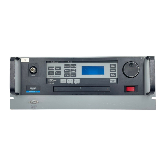
Page 9: Discrete Controls & Indicators
TECHNICAL NOTE – OPERATION OF MT4000 TWTA 10/24/03 Discrete Controls & Indicators The indicators & controls described in this section are provided on the HPA front panel. Further description of these functions follows in later sections of this document. 3.1.1 Filament Off Button/LED When this button is activated, from any state except Transmit, the Filament Power Supply will be turned off. - Page 10 TECHNICAL NOTE – OPERATION OF MT4000 TWTA 10/24/03 3.1.8 RF Off Button/LED When this button is activated the HPA will disable the SSA RF switch. When the Yellow LED inside the button is illuminated, the SSA RF switch is disabled.
- Page 11 TECHNICAL NOTE – OPERATION OF MT4000 TWTA 10/24/03 3.1.17 Remote Button/LED When this button is activated the HPA will allow the device (remote panel) on the remote interface to control the HPA operating configuration. When the Yellow LED inside the button is illuminated, the amplifier is controlled via the remote serial port.
- Page 12 TECHNICAL NOTE – OPERATION OF MT4000 TWTA 10/24/03 3.1.25 Accept Button This button will be used to select adjustable parameter on any screen. 3.1.26 Menu Select Button This button is used to move between different menus on the display. TN4000-3 MCL, INC.
-
Page 13: Front Panel Display & Screen Content
TECHNICAL NOTE – OPERATION OF MT4000 TWTA 10/24/03 Front Panel Display & Screen Content This figure shows an overview of the TWTA screens and the flow between these screens. The following paragraphs describe each screen and how the operator will move between them. - Page 14 TECHNICAL NOTE – OPERATION OF MT4000 TWTA 10/24/03 3.2.1 Title Screen The title screen will be displayed when the TWTA first powers on and will remain on while startup testing and a lamp test is performed. This will not exceed 5 seconds.
- Page 15 TECHNICAL NOTE – OPERATION OF MT4000 TWTA 10/24/03 3.2.4 Main Menu Screen This screen is accessed from the normal screen. When the menu screen shown below is displayed the operator can select from the functions listed on this menu. Though there are six menu selections, the screen can only display four at a time.
- Page 16 TECHNICAL NOTE – OPERATION OF MT4000 TWTA 10/24/03 3.2.6 Adjustment Menu Screen This screen is accessed from the menu screen. When the screen shown below is displayed the operator can select which parameter to modify from those listed on this menu. Notice there are seventeen menu selections, but the screen can only display four at a time.
- Page 17 TECHNICAL NOTE – OPERATION OF MT4000 TWTA 10/24/03 3.2.8 Event Log Screen This screen is accessed from the menu screen. When the screen shown below is displayed the most recent event in the log will be presented. The event log is stored in Non-Volatile memory on the HPA and will contain operational state changes, alarms, and faults, which have occurred in the HPA.
- Page 18 TECHNICAL NOTE – OPERATION OF MT4000 TWTA 10/24/03 FAULTS Tube Temp Switch Chassis Interlock RF Reflected Tube Overdrive Helix Surge User Interlock W.G. Arc HV Over Volt Filament Under Current Tube Temp Analog HV Primary Current P.S. Temperature Helix Run W.G.
- Page 19 TECHNICAL NOTE – OPERATION OF MT4000 TWTA 10/24/03 3.2.10 Coupling Factor Screen On this screen the operator can edit or view the frequency and coupling factor for up to eight frequencies for the TWTA output sample port. These coupling factors are a convenience for the operator and are not used in any calculations within the TWTA logic.
- Page 20 TECHNICAL NOTE – OPERATION OF MT4000 TWTA 10/24/03 3.2.12 Coupling Factor Parameter Edit Screen This screen is accessed from the coupling factor edit line screen. The screen shown at bottom of the figure above is a typical EDIT screen for coupling factor parameters. While one of these screens are displayed the operator can use the adjustment knob to change the parameter shown on the fourth line.
-
Page 21: Hpa Operation
TECHNICAL NOTE – OPERATION OF MT4000 TWTA 10/24/03 3.2.15 Fault & Alarm Display The fault & alarm display screen automatically becomes active whenever a fault or alarm occurs or when the TWTA is put into Local Override. This screen will capture the four most recent faults and alarms that occur at the same time. - Page 22 HPA (see TN4000-2 Technical Note, Installation Guide for MT4000 TWTA). Status LEDs on the HPA front panel are connected to the transmitted and received data lines of this interface to provide communications status.
- Page 23 TECHNICAL NOTE – OPERATION OF MT4000 TWTA 10/24/03 PARAMETER DEFAULT ADJUSTMENT RANGE COMP PROTOCOL CSP (46A0204 & 40A1546) or SABUS (46A0203 & 40A1715) COMP ADDRESS 01 through 7F (CSP) (Hexadecimal) 31 through 7E (SA7670) 9600 1200, 2400, 3600, 4800, 9600, 14400,...
-
Page 24: Hpa Operating Modes
TECHNICAL NOTE – OPERATION OF MT4000 TWTA 10/24/03 HPA Operating Modes The following paragraphs describe the operating states of the HPA. The reported status for these states is shown in the table below. STATUS STATE DELAY STBY SELD FAULT DC POWER ON, NO FILAMENT... -
Page 25: Rf On/Off Control
TECHNICAL NOTE – OPERATION OF MT4000 TWTA 10/24/03 4.2.2 Filament Delay This state occurs after a Standby command (Local, Remote, or Computer) has been issued. During this state all TWTA circuitry will be activated except the high voltage power supply. At the end of this delay the TWTA will be in the Standby mode. -
Page 26: Faults & Alarms
TECHNICAL NOTE – OPERATION OF MT4000 TWTA 10/24/03 Local panel button Remote interface Computer interface Switchover interface User interface Tube Overdrive Fault 4.3.2 RF On State While the HPA is in the RF On mode the SSA module RF switch will be in the RF On state. All of the above control sources must be in the RF On state to allow the HPA to enter RF On. - Page 27 TECHNICAL NOTE – OPERATION OF MT4000 TWTA 10/24/03 4.4.2 Summary Fault All faults that are listed in the table below will cause a Summary Fault; notice the Second HPA Switchover fault is not included in this list. While a Summary Fault condition is present, the following will be true until a fault reset occurs: The fault LED on the Reset button will remain illuminated.
- Page 28 TECHNICAL NOTE – OPERATION OF MT4000 TWTA 10/24/03 4.4.5 Fault & Alarm Trip Levels Set on the Front Panel Some fault & alarm trip levels associated with an analog display are adjustable by the operator at the HPA front panel (see the Adjustment Menu Screen paragraph of this document), and through the Remote or Computer interfaces.
-
Page 29: Hpa Gain Control
TECHNICAL NOTE – OPERATION OF MT4000 TWTA 10/24/03 The number of faults counted and the window of time during which they are counted are both adjustable by the operator (see the Adjustment Menu Screen paragraph of this document). The window size must be greater than five times the number of faults counted in seconds. - Page 30 TECHNICAL NOTE – OPERATION OF MT4000 TWTA 10/24/03 4.5.2.2 Conditions That Will Prevent Auto Power From Turning On The HPA will refuse to perform an Auto Power command if any of the following conditions are present. If the TWTA is not in Transmit.
-
Page 31: Diagnostic Interface
TECHNICAL NOTE – OPERATION OF MT4000 TWTA 10/24/03 Diagnostic Interface A RS232 diagnostic interface (J8) is provided on the front panel of the MT4000. This interface is designed to connect to a PC through a standard RS232 9-pin cable. Through this interface the... - Page 32 TECHNICAL NOTE – OPERATION OF MT4000 TWTA 10/24/03 From this screen you cannot change any settings or operating states of the HPA. 4.6.2 Downloading Settings On the Diagnostic Interface program click on the “Settings” tab (see the figure below). Click on the “Download All Settings” button to refresh the settings display.
- Page 33 TECHNICAL NOTE – OPERATION OF MT4000 TWTA 10/24/03 On this screen some parameters are displayed only, others can be modified individually. The “Control Mode” set button is nonfunctional on the MT4000. 4.6.3 Uploading Setting to the HPA The HPA must be in a maintenance mode (the HPA is not transmitting on the antenna). It must be in Local and not carrying traffic or an interruption in service may occur.
- Page 34 TECHNICAL NOTE – OPERATION OF MT4000 TWTA 10/24/03 4.6.4 Downloading the Event Log On the Diagnostic Interface program click on the “Event Log” tab (see the figure below). Click on the “Download” button to refresh the status. To save the data to disc, once the status is done downloading, click on the “File”...
- Page 35 TECHNICAL NOTE – OPERATION OF MT4000 TWTA 10/24/03 4.6.5 Down Loading Calibration Tables from the HPA On the Diagnostic Interface program click on the “Cal Tables” tab (see the figure below). Click on the “Download Tables” button. Once the tables are done downloading, click on the “File” menu, select “Save” on that menu, then on the Save menu select “Calibration.”...
- Page 36 TECHNICAL NOTE – OPERATION OF MT4000 TWTA 10/24/03 4.6.7 Graphing Tab Data stored in the database can be viewed in graphical form on this TAB. If data is automatically updating and saved to the database the graph will also automatically update.
- Page 37 TECHNICAL NOTE – OPERATION OF MT4000 TWTA 10/24/03 TN4000-3 MCL, INC. 37 of 46...
-
Page 38: Optional Local Interface Override
TECHNICAL NOTE – OPERATION OF MT4000 TWTA 10/24/03 4.7 Optional Local Interface Override The Local Interface Override is an optional CCA which when activated will temporarily provide rudimentary emergency control of the amplifier in the event of a failure of the VFD display, membrane panel, or the controller. -
Page 39: Optional Linearizer
TECHNICAL NOTE – OPERATION OF MT4000 TWTA 10/24/03 4.7.4 Filament Delay During Local Override There is not a "Filament Off" or "Transmit Selected" state while in Local Override mode. There is no Proportional delay while in the Local Override mode. The Filament Under fault will be disabled while the HPA is in the Local Override mode. -
Page 40: User Interface J6
4.9.2 Other Redundant Systems All other redundant systems whether they are MCL systems (such as MT4012, MT40PC, ..) use only a small portion of the signals on J7. Depending on the system type the Switchover Fault... - Page 41 TECHNICAL NOTE – OPERATION OF MT4000 TWTA 10/24/03 4.11.2 Procedure to Limit RF Input to the HPA 1. Rated Power No Attenuation With the HPA attenuation at minimum, measure the amount of power required to drive the MT4000 system to rated power (this is also shown on the data sheet sent with the equipments.
-
Page 42: Initial Turn On Of The Hpa
TWTA. 3. MT4000 Trip Levels The Tube Overdrive Fault and the Tube Overdrive Alarm levels were set by MCL to protect the TWT. If the Tube Overdrive Alarm occurs this is an indication to the operator that the tube drive level is approaching the Tube Overdrive Fault. -
Page 43: Operating Caution List
TECHNICAL NOTE – OPERATION OF MT4000 TWTA 10/24/03 Ground strap (earth) attached to safety ground stud on rear panel of MT4000. Appropriate AC input voltage and frequency has been connected to the MT4000. Check AC system voltages by measuring the voltage on the mate for J1 (AC input connector). -
Page 44: Power-Up Procedure
TECHNICAL NOTE – OPERATION OF MT4000 TWTA 10/24/03 CAUTION Failure to avoid above conditions will void warranties!! Any of these conditions indicate that a critical system parameter is either out of adjustment or the fault conditions are no longer recognizable. If these conditions should exist, no further attempt should be made to use the amplifier system until the defective circuitry or adjustment is corrected. - Page 45 TECHNICAL NOTE – OPERATION OF MT4000 TWTA 10/24/03 CAUTION Never activate transmit unless an RF load is connected to the RF output. Avoid operating the system in standby for more than 60 minutes; use the Filament Off control for long periods of Standby. See 46A0009 Extending Tube Life Information this document is include as an appendix to TN4000-5 Preventative Maintenance for MT4000.
-
Page 46: Shut Down Procedure
This completes the procedure necessary to bring the MT4000 TWT amplifier system into full and complete system operation. The MT4000 TWTA transmitter system is now fully operational and will stay functional until either operator shutdown or a fault condition is detected. - Page 47 TECHNICAL NOTE – OPERATION OF MT4000 TWTA 10/24/03 APPENDIX A 40A1546 CSP Protocol Specification APPENDIX B 40A1715 SA Bus Compatible Protocol Specification APPENDIX C 46A0204 CSP Command Set APPENDIX D 46A0203 SA Bus Command Set TN4000-3 MCL, INC.
Need help?
Do you have a question about the MT4000 TWTA and is the answer not in the manual?
Questions and answers