Table of Contents
Advertisement
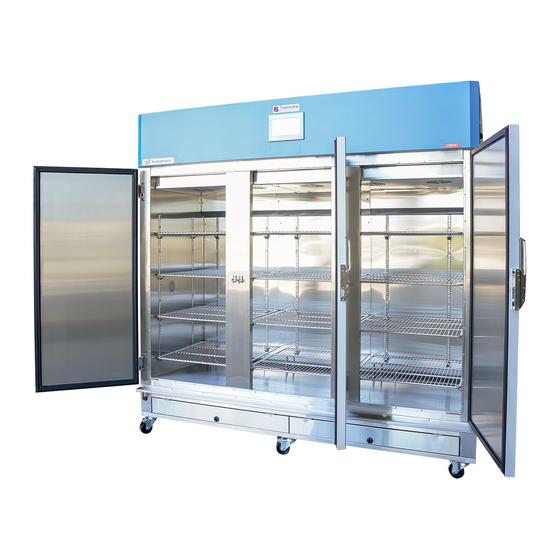
TEMPERATURE AND HUMIDITY CHAMBERS
P.O. Box 6862, Wetherill Park Delivery Centre, N.S.W. 1851. Australia.
HUMIDITHERM
MODELS INCLUDE:
TRH-1250
TRH-2000
WITH STAR-700 CONTROL
Thermoline Scientific Equipment Pty. Ltd.
T/A
Thermoline Scientific
10-12 Ross Place. Wetherill Park. N.S.W. 2164. Australia.
Phone: (02) 9604 3911. International: 61 2 9604 3911.
Fax (02) 9725 1706. International: 61 2 9725 1706.
Email:
sales@thermoline.com.au
ABN 80 000 859 129
Web:
www.thermoline.com.au
Advertisement
Table of Contents

Summary of Contents for Thermoline TRH-1250
- Page 1 TEMPERATURE AND HUMIDITY CHAMBERS MODELS INCLUDE: TRH-1250 TRH-2000 WITH STAR-700 CONTROL Thermoline Scientific Equipment Pty. Ltd. Thermoline Scientific ABN 80 000 859 129 10-12 Ross Place. Wetherill Park. N.S.W. 2164. Australia. P.O. Box 6862, Wetherill Park Delivery Centre, N.S.W. 1851. Australia.
-
Page 2: Table Of Contents
IMPORTANT INFORMATION This manual contains operating and safety information. The operator must read and understand the contents of this manual prior to using this equipment. Incorrect operation may cause harm or damage the severity is classified by the following Alert Boxes. Ensure that this manual is saved for future reference: Warning alerts apply when there is a Possibility of personal injury. -
Page 3: Product Warranty
Notwithstanding the preceding clause and to the extent permissible by law, the liability of Thermoline is limited, in relation to the warranted product and at the option of Thermoline to: ... -
Page 4: Introduction
Extra shelves. 1 x 4 pin plug for BMS Connection. Retain the packaging materials until the equipment has been thoroughly tested. Notify the detail of any damage without delay to your supplier, or Thermoline Scientific. P a g e... -
Page 5: Location & Services Required
Total Residual Deposits to a minimum can result in premature failure of the Humidifier Tank. An alternative method to Mains water is to use a water supply from a gravity fed tank. Thermoline supply an optional 25 litre water tank complete with flexible hose and connection fittings. This should be elevated by at least 1 metre and filled with water, the 25 litres would last at least 2 ½... -
Page 6: Assembly & Installation
DRAIN: Because we are controlling humidity levels inside the cabinet, there will always be water condensing and coming out of the drain inside the cabinet. There is also a drain valve on the humidifier tank for maintenance, and an overflow pipe in case of a malfunction. Therefore it is essential that the location for the cabinet has a floor drain for the water to flow into. - Page 7 INSTALLATION: Locate the cabinet in a well ventilated area on a firm level surface as described earlier. Make sure that the 2 x wall spacing rods are screwed into the frame at the rear of the cabinet (See figure 1). This will ensure that the air flow through the refrigeration condenser is not impeded.
-
Page 8: Function
FUNCTION: This equipment is used to provide an economical and accurate temperature and humidity controlled environment for laboratory evaluation and long term storage of products, within the range shown below in the TRH control envelope. WARNING: Do not use flammable solvents or combustible materials as fire or explosion may occur. - Page 9 TEMPERATURE: The air is heated by means of an element below the false floor, and cooled by means of the bare pipe evaporator. The refrigeration unit is located in the area below the cabinet. The STAR-700 controller cycles the heating and cooling to maintain stable temperature. HUMIDITY: The air is humidified by steam from the steam generator located in the area below the main cabinet.
-
Page 10: Explanation Of Controls
EXPLANATION OF CONTROLS Access: The STAR-700 Controller is located in the front door. On initial power up the STAR-700 displays the screensaver. See STAR-700 Operating Guidelines on how to exit screensaver mode. Figure 3: Control Panel. Temperature/Humidity Control: The STAR-700 microprocessor controller allows accurate control of the Temperature and Humidity with in the cabinet. -
Page 11: Other Controls
Figure 4: Humidifier Components. OTHER CONTROLS: Element Safety Thermostat: This is a factory set thermostat that will only trip in the event that the cabinet exceeds its maximum temperature of 60.0degC. Water Pressure Regulator: Located behind the hinged access panel in the base of the cabinet. Needle Valve: Located behind the water pressure regulator. -
Page 12: Operating The Cabinet
OPERATING THE CABINET 1) Ensure that the cabinet is located as previously described, refer to the index, LOCATION, Page 4. 2) Loading/Unloading the Cabinet Load Distribution There is a direct relationship between the temperature/humidity uniformity throughout the workspace and the air distribution. If the air cannot freely circulate, then the controlled conditions cannot be maintained. -
Page 13: Star-700 Operating Guidelines
‘STAR-700’ TOUCHSCREEN OPERATING GUIDELINES. Safe Operating Value (SOV). On initial Power up the STAR-700 Touchscreen shows the Screen Saver page. See Below Image. On Initial power up cabinet controls the ‘Safe Operating Value’ only. The Touchscreen is fitted with a Security Screensaver to stop unauthorised access to the controlling parameters. This Security Screensaver becomes active if the Touchscreen has not been touched for more than 5minutes or if power is cycled. - Page 14 Security Screensaver with User Access Window. Main Menu Screen (SOV Mode) Main Menu Screen with Pop-Up Numeric Keypad. 14 | P a g e...
-
Page 15: Program Setup
Programs (10 Segments per program). The Program Set-Up is securely protected by means of a user name and password. By pressing the Thermoline Logo the Login Screen appears. The Username is 02 and the Password is 2222. Once the Password is entered the next touch of the screen needs to be the ‘Program Set-Up’... - Page 16 Each program can be set as an independent program or can be linked to create one large or multiple large programs. This is achieved by not using an End segment in a particular program. For example if your program requires the use of 15 segments we can use the 10 segments of Program 1 and the first 5 segments of Program 2 making Segment 15 (5 Segment of Program 2) an End Segment type.
- Page 17 Segment Type: The segment type can either be a Time, Jump To, or End type. Time: This determines that the segment is a period of time. The time is set in Hours, Minutes and Seconds. Jump To: This allows the program to repeat a predetermined set of segments.
- Page 18 G’Soak Humidity: This is the Guaranteed Soak Parameter and is only visible if the Guaranteed Soak is enabled. This parameter is generally not used on the Climatron range of Plant Growth Cabinets as it can extend the time of a Diurnal Program effectively making the Diurnal Cycle longer than 24hours.
- Page 19 Program 1 Lighting/Event Segment 6-10 Program Features. There are a few other features of the program that cannot be changed but are described below. Guaranteed Soak: This is a tolerance value, set at +/-2.0degC, and guarantees that the Program Set Values for Temperature only are reached. If during a program cycle the Actual Temperature deviates the Program Set Value (PSV) by more than +/-2.0degC the program will be put into a hold mode until the Actual Temperature is within the PSV.
-
Page 20: Starting Program
Starting the Diurnal/Program. The following screen shows the Diurnal/Program Set-Up screen. Once the desired program has been set up then the operator will need to enter the desired program number value into Start Program Number. Once the desire value has been entered the operator can then start the program by using the drop down menu. - Page 21 Main Screen (SOV) Showing Program/Diurnal Drop Down Menu. Main Screen (PSV Mode) 21 | P a g e...
-
Page 22: Trend Screen
Trend Menu The images below are the Trend and the Co2 Trend Screen. They show a live trend of the performance of the cabinet. The screen shows the last 12hr period. By pressing the left pointing arrows the screen scrolls back to view a graphical depiction of the previous period from power up. A total of approximately 800days of logging can be viewed. -
Page 23: Data Menu
Data Menu By pressing the “Data Menu” Button the image below is displayed. On this screen Data can be retrieved for archiving purposes. Insert a USB Memory Card into the USB port at the front of cabinet. Keep watching the screen for the following message “USB Disk/SDMMC Card Plugin” Once this message has been viewed the operator can press the “Download Data to USB”... -
Page 24: Security Screensaver
Security Screensaver. The Touchscreen is fitted with a Security Screensaver to stop unauthorised access to the controlling parameters. This Security Screensaver becomes active if the Touchscreen has not been touched for more than 5minutes or if power is cycled. If the Touchscreen has not been touched for more than 10minutes the Backlight switches off and the screen goes blank. - Page 25 Security Screensaver (PSV) with Pop-Up Login Message To exit out of the Security Screensaver simply press the close button. Then press the ‘Press to Log In & Exit Screensaver’ Button. The User Access window will appear. Security Screensaver (PSV) with User Access Window. To exit out of the Security Screensaver and enter into the Main Menu Screen use the following passcodes: User Number: 1...
- Page 26 Security Screensaver with Pop-Up Numeric Keypad. As soon as you have pressed enter simply touch the screen anywhere within the Black rectangle. The Touchscreen will then show the Main Screen as shown below. Main Menu Screen (PSV Mode) 26 | P a g e...
-
Page 27: Calibration Screen
Calibration Screen. The Thermoline Touchscreen has been fitted with a simple one point calibration adjustment. Access to the Calibration is password protected. To access simply touch the Thermoline Logo and the User Access window will appear. Main Menu Screen with User Access Window... -
Page 28: System Settings & Codes
System Screen Service Screen. This screen is for the sole purpose of our service technicians or service contractors. This is a password protected screen and is only accessible by authorised Thermoline Technicians or Authorised Thermoline Contract Technicians. 28 | P a g e... -
Page 29: Diagnostics
It also shows the percentage output of each control function. This is a good diagnostic tool if the cabinet is not operating correctly. Diagnostic Screen. Contact Screen The Image Below is the Thermoline Contact Page. Contact Screen. 29 | P a g e... -
Page 30: Maintenance
MAINTENANCE Apart from the normal levels of cleanliness, the cabinet should be regularly maintained to ensure trouble free operation. A “periodic inspection and maintenance” programme can be arrange in some Australian locations. Lubrication of moving parts is not necessary since all bearings are sealed, but there are one or two essential maintenance chores that should be performed regularly: CLEANING: The internal and external surfaces of the cabinet can be cleaned with a soft damp cloth. -
Page 31: Water-Flow Adjustment
WATER FLOW ADJUSTMENT: Water regulator: This valve is used to reduce water pressure and to stop float switch “bounce” when water is injected into the humidifier tank. Needle valve: This valve is designed to adjust the flow of water into the humidifier tank. If the water pressure regulator or needle valve need to be adjusted use the following procedure below: When mains water is connected to the cabinet:... - Page 32 61 2 9725 1706 Email: thermoline@thermoline.com.au Please note that information provided in this manual is confidential and the property of Thermoline Scientific. It may not be copied or distributed without permission. Information provided in this manual may be subject to change without notice.
Need help?
Do you have a question about the TRH-1250 and is the answer not in the manual?
Questions and answers