Table of Contents
Advertisement
Advertisement
Table of Contents

Summary of Contents for IBA ibaPADU-S-CM
- Page 1 Central unit for the iba modular system Manual Issue 1.9...
- Page 2 However, the information in this publication is updated regularly. Required corrections are contained in the following regulations or can be downloaded on the Internet. The current version is available for download on our web site www.iba-ag.com. Copyright notice ®...
-
Page 3: Table Of Contents
Safety instructions ..................9 Proper use ....................9 Special safety instructions ................9 System Requirements ................... 10 Hardware ....................10 Software ...................... 10 ibaPADU-S-CM ................... 10 Mounting, Connecting, Dismounting ............11 Mounting ......................11 Dismounting ....................11 Device description ..................12 Device views ....................12 Indicator elements .................. - Page 4 PADU-S – Diagnostics tab ................24 10.2.2 PADU-S – Analog tab .................. 25 10.2.3 PADU-S – Digital tab ................... 26 10.2.4 ibaPADU-S-CM – General tab ..............27 10.2.5 ibaPADU-S-CM – Digital tab ................ 27 10.2.6 10.2.7 Diagnostics signals ..................28 Technical Data ....................
-
Page 5: About This Manual
Manual About this manual In this manual, you learn a lot about the design of the ibaPADU-S-CM device and how to use and operate it. You can find a general description of the systems of the iba-mod- ular system and further information about the design of the modules and how to use and operate them in separate manuals. -
Page 6: Target Group
Manual ibaPADU-S-CM Target group This manual addresses in particular the qualified professionals who are familiar with han- dling electrical and electronic modules as well as communication and measurement tech- nology. A person is regarded to as professional if he/she is capable of assessing safety and recognizing possible consequences and risks on the basis of his/her specialist training, knowledge and experience and knowledge of the standard regulations. -
Page 7: Used Symbols
Manual Used symbols If safety instructions or other notes are used in this manual, they mean: The non-observance of this safety information may result in an imminent risk of death or severe injury: By an electric shock! ... -
Page 8: Introduction
The ibaPADU-S-CM CPU offers 8 digital inputs. When equipped with the right input/output modules and combined with the ibaPDA soft- ware, ibaPADU-S-CM can be used for fast applications in the fields of data capturing and recording. Examples of applications are as follows: ... -
Page 9: Safety Instructions
Never supply the device with a voltage other than 24 V DC +/- 10%! A higher voltage may destroy the device or be dangerous to life! Modules and CPU must NOT be attached or detached to/from the rack under voltage! Switch off ibaPADU-S-CM or disconnect power supply before attaching/detaching the modules. Important Note... -
Page 10: System Requirements
Manual ibaPADU-S-CM System Requirements Hardware For operation Power supply DC 24 V ± 10 %, 3 A (fully equipped) Backplane unit, e.g. ibaPADU-B4S (see chap. 12, „Accessories and related prod- ucts“) For parametrization of the device and for measuring: ... -
Page 11: Mounting, Connecting, Dismounting
Manual Mounting, Connecting, Dismounting Works on the device must NOT be done when it is under voltage! Mounting 1. Mount the backplane on an appropriate construction. 2. Connect the ground terminal . 3. Attach the device to the left slot. -
Page 12: Device Description
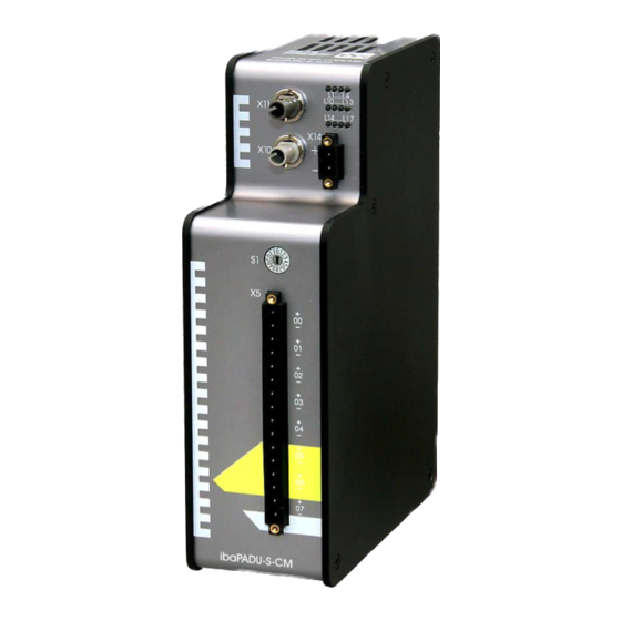
Manual ibaPADU-S-CM Device description Device views Operating status indicators L1 … L4 Status LED digital inputs L10 … L17 Connector for power supply 24 V X14 Rotary switch S1 Connection for digital inputs X5 Fixing screws Connection FO output (TX) X10... -
Page 13: Indicator Elements
Disturbance, applications internal to the device do not run. Device failure (during start up) Important Note When the LED L4 indicates a failure, please contact the iba Support. Please mention the number of times, the LED L4 is flashing. 7.2.2 Status of digital inputs L10 to L17 The green LEDs show whether a digital input is on or off. -
Page 14: Operating Elements
Manual ibaPADU-S-CM Operating elements 7.3.1 ON/OFF switch S11 Position Status Description Switched on, voltage applied Switched off, no voltage applied When switching off the device and then on again, the supply voltage is switched off/ connected and the device is rebooted. -
Page 15: Digital Inputs X5
For the digital inputs, there are four debounce filters for each. These can be chosen and configured for each signal independently with the I/O Manager of ibaPDA. You have got the following filters at your disposal: For further information see chapter 10.2.6 “ibaPADU-S-CM – Digital tab”. „Off“ (without filter) „Stretch rising edge“... - Page 16 Manual ibaPADU-S-CM The measured input signal is transferred without filtering. „Stretch rising edge“ With the first rising edge, the input signal (red) switches to logical 1 and keeps this value for the defined debounce time. Thereafter, the channel is transparent again and waits for the next rising edge.
-
Page 17: Voltage Supply X14
Manual „Delay both edges“ Beginning with the first edge, the output signal (purple) blocks the input and keeps the logical value of the edge for the duration of the defined debounce time. Thereafter, the channel is transparent again, directly assumes the logical level of the input signal and waits for the next edge –... -
Page 18: System Integration
System integration Application examples The figures below show examples of ibaPADU-S-CM combined with ibaPDA. The shown examples can be integrated in other iba systems or external systems, re- specting the technical requirements. 8.1.1 Measuring system with ibaPDA Figure 9: Measuring system with ibaPDA ... -
Page 19: Updates
Please do not switch off the device when an update is running. This might damage the device. Installing an update can take some minutes. When installing a firmware update, the entire iba modular system will be updated, i.e. the CPU and the I/O modules attached to the system. When the update is completed, the device reboots automatically. - Page 20 (i.e. it is more recent than the firmware version of the CPU), this module is ignored and is not displayed in ibaPDA. In this case, a new update file has to be installed for the “overall release version“. If you want to get the current update file, please contact the iba Support. Issue 1.9...
-
Page 21: Configuration With Ibapda
Start ibaPDA, open the I/O Manager and proceed as follows: 1. Look in the I/O Manager for the link of the FOB-D card, ibaPADU-S-CM is connected to. Click with the right mouse button on the link. The submenu is opened. Choose “Autodetect“:... - Page 22 5. Click on the “General” tab on “Read configuration from device“. The connected modules are detected automatically and shown in the signal tree. 6. Configure ibaPADU-S-CM and the modules (e.g. assign a name, debouncing, etc.) (see chapter 10.2 „Modules in ibaPDA“).
-
Page 23: Modules In Ibapda
Name You can enter a name for the module Timebase Specifies the time base for data capturing that is used for ibaPADU-S-CM and the connected modules. Use name as prefix Select „True“, if you want to prefix the signal names with the module name. -
Page 24: Padu-S - Diagnostics Tab
Write firmware Using this button you can install a firmware update. Select the update file „paduscm_v[xx.yy.zzz].iba “ in the browser and start the update with <OK>. Important note The update may take several minutes and must not be interrupted. After an update the device will be automatically rebooted. -
Page 25: Padu-S - Analog Tab
Manual PADU-S – Analog tab 10.2.3 Note The “Analog“ tab appears when signal capturing with the analog input modules has been started. In the list, you can see the configured analog signals and the current values. Figure 13: PADU-S module – „Analog“ tab... -
Page 26: Padu-S - Digital Tab
Manual ibaPADU-S-CM PADU-S – Digital tab 10.2.4 Note The “Digital“ tab appears when signal capturing with the digital input modules has been started. In the list, you can see the configured digital signals and the current values. Figure 14: PADU-S module – „Digital“ tab... -
Page 27: Ibapadu-S-Cm - General Tab
Manual ibaPADU-S-CM – General tab 10.2.5 Figure 15: ibaPADU-S-CM module – „General“ tab Basic settings Module Type, Locked, Enabled, Name, Timebase, Use name as prefix see chapter 10.2.1 „PADU-S – General tab“ Module No. Logical module number for clearly referencing the signals, e.g. in expressions and for the ibaAnalyzer. -
Page 28: Diagnostics Signals
Manual ibaPADU-S-CM Debounce filter In the dropdown menu, you can choose the operating mode for the debounce filter. You have got the following settings at your disposal: Off, stretch rising edge, stretch falling edge, stretch both edges, delay both edges. - Page 29 Manual 10.2.7.1 Diagnostics – General tab Figure 18: Diagnostics module – “General” tab Basic settings Module Type, Locked, Enabled, Name, Module No., Use name as prefix see chapter 10.2.1 “PADU-S – General tab“. Timebase The timebase is related to the general acquisition timebase of the ibaPDA system.
- Page 30 Manual ibaPADU-S-CM The diagnostics signals can be activated individually. The meaning of the signals: Signal Meaning Hardware state Indicates whether the IO module is ready for op- eration. Hardware available Indicates whether the IO module has been de- tected and initialized properly during startup.
-
Page 31: Technical Data
Manual Technical Data 11.1 Main data Short description Name ibaPADU-S-CM Description CPU for data acquisition system Order number 10.124030 Supply, operating and indicator elements Voltage supply 24 V DC ± 10 %, not stabilized, 200 mA (without I/O modules), 3 A (with I/O modules) -
Page 32: Digital Inputs
Manual ibaPADU-S-CM 11.3 Digital inputs Digital inputs Number Design Galvanically isolated, protected against reverse polarity, sin- gle ended Input signal 24 V DC Max. input voltage ±60 V permanent Signal level log. 0 > -6 V; < +6 V Signal level log. 1 <... -
Page 33: Dimensions
Manual 11.4 Dimensions ibaPADU-S-CM (Dimensions in mm) Figure 20: Dimensions ibaPADU-S-CM (Dimensions in mm) Figure 21: Dimensions ibaPADU-S-CM with cables Issue 1.9... - Page 34 Manual ibaPADU-S-CM Distance between 2 iba modular systems (Dimensions in mm) Figure 22: Min. distance between 2 iba modular systems Issue 1.9...
- Page 35 Manual ibaPADU-S-CM and backplane (Dimensions in mm) Figure 23: Dimensions ibaPADU-S-CM with backplane Issue 1.9...
- Page 36 Manual ibaPADU-S-CM Mounting plate 19“ (Dimensions in mm) Figure 24: Dimensions of mounting plate Issue 1.9...
- Page 37 Manual Backplane ibaPADU-S-B4S (Dimensions in mm) Figure 25: Dimensions ibaPADU-S-B4S Backplane ibaPADU-S-B4S with mounting angles (Dimensions in mm) Figure 26: Dimensions ibaPADU-S-B4S with mounting angles Issue 1.9...
- Page 38 Manual ibaPADU-S-CM Backplane ibaPADU-S-B1S for one central unit and one module (Dimensions in mm) Figure 27: Dimensions ibaPADU-S-B1S (Dimensions in mm) Figure 28: Dimensions ibaPADU-S-B1S with modules Issue 1.9...
- Page 39 Manual Backplane ibaPADU-S-B for one central unit (Dimensions in mm) Figure 29: Dimensions ibaPADU-S-B Issue 1.9...
-
Page 40: Connection Diagram
Manual ibaPADU-S-CM 11.5 Connection diagram 11.5.1 Pin assignment voltage supply 24 V (X14) Connection + 24 V DC, voltage supply 11.5.2 Pin assignment digital inputs (X5) Connection Digital input 00 + Digital input 00 - Digital input 01 + Digital input 01 -... -
Page 41: Accessories And Related Products
Manual Accessories and related products Backplane ibaPADU-S-B4S Order number 10.124000 Backplane panel (for carrying components) for 1 central unit and up to 4 I/O modules w x h x d: 9.02 in x 8.62 in x 0.83 in (229 mm x 219 mm x 21 mm) - Page 42 Manual ibaPADU-S-CM Mounting panel 19“ for PADU-S modular Order number 10.124005 Mounting panel (483 mm/19“) for up to two ibaPADU-S-B4S backplanes Mounting 1 ibaPADU-S-B4S centered or 2 ibaPADU-S-B4S left and right Mounting accessories included in delivery Module Carrier for ibaPADU-S modular system Order number 10.124007...
- Page 43 30.620480 For up to 2048 signals ibaAnalyzer 33.010400 Offline- and online analysis software with free license if used to analyze *.dat files generated by licensed iba software. For further accessories, please see our online catalog at /www.iba-ag.com. Issue 1.9...
-
Page 44: Appendix
To ensure that the IO modules used with ibaPADU-S-IT-05 can also be used with the new central unit ibaPADU-S-CM, an upgrade be has to be installed on the modules at iba. Therefore the modules need to be sent to iba. Please contact the iba support for this purpose. -
Page 45: Ftp Connection To The Device
\02_iba_Hardware\ibaPADU-S-CM\USB_Driver 3. After having installed successfully, an additional network connection is available with the device name „IBA AG USB Remote NDIS Network Device“. 4. A fixed IP address must be assigned to this interface. The address has to be from this range: 192.168.0.n with n = 2…254 and the subnetmask 255.255.255.0. -
Page 46: Configuration Of The Ibanet Protocol 32Mbit
Manual ibaPADU-S-CM 13.1.2 Configuration of the ibaNet protocol 32Mbit Copy the file “Config_StaticFO.xml” to your computer and open the file with an editor. The two green marked regions describe a template for the configuration and the default configuration “StaticFO-IO” configuration of the ibaNet protocol 32Mbit. - Page 47 - for 64 analog INT and 64 digital signals per slot Real16x32 - for 32 analog REAL and 32 digital signals per slot <Property Name="FO_Slot" Value="0" Unit=""/> Only relevant when configuring a chain: Specifies the corresponding slot of the ibaPADU-S-CM system. At least: 0 (default) 0 … 15 Allowed values: Issue 1.9...
- Page 48 Manual ibaPADU-S-CM <Property Name="FO_Period" Value="50" Unit="us"/> This value depends on the configured/required number of signals (FO_Signals): Int64A+64D Real32A+32D Int128A+128D Real64A+64D Int16x8 Int256A+256D Real128A+128D Int512A+512D Real256A+256D Int1024A+1024D Int16x64 1000 Real512A+512D Real16x32 The following four properties describe the offset of the signals in the FO configuration: ...
- Page 49 Manual <Property Name="Use_Output_StatusSignals" Value="false" /> The status signals of the output modules (output signal is available) are used in the FO configuration <Property Name="Use_Output_ControlSignals" Value="false" /> The error signals of the output modules are used in the FO configuration ...
- Page 50 Manual ibaPADU-S-CM 5. Wait approx. 10 seconds until the file “FoSignalList.txt” has been automatically up- dated. If necessary refresh the display by pressing <F5>. Finally, you may copy the file to your computer. Note If a new file “Err_Config_StaticFO.xml” appears after 10 seconds waiting time (refresh the display with <F5>), there may be an error in the FO configuration file.
-
Page 51: Features Of The Staticfo Function
Manual 13.1.3 Features of the StaticFO function 13.1.3.1 Limited number of signals Regardless of the fiber optic mode activated via the "FO_Signals" property, only a fixed number of analog and digital signals is available for transmission. In "Real64A+64D" mode, for example, a maximum of 64 analog and 64 digital signals are available. -
Page 52: Special Features Ibapadu-S-Cm Chain
13.1.4 Special features ibaPADU-S-CM chain Up to 16 ibaPADU-S-CM systems can be connected in a line topology (chain) with iba software or other iba components. Each fiber optic output of an ibaPADU-S-CM system is connected to the next fiber optic input until all devices of a line are connected to the ibaFOB card. - Page 53 Manual The region “Fiber optic settings” indicates that the ibaNet protocol 32Mbit is set here. The mapping of the IO signals and the FO configuration is shown in the signal list. The signals are grouped by signal type and signal direction.
-
Page 54: Analyzing An Invalid Configuration
Note If ibaPADU-S-CM is reset to factory defaults with ibaPDA and 32Mbit Flex, the 32Mbit configuration will be reset too (after power off/on). The configuration file, which might have been modified and enhanced with new entries, will be deleted and replaced by the default configuration file. -
Page 55: Index
Manual Index 32Mbit Flex 14, 18 I/O Manager IP address via FO Application examples Mounting Backplane 11, 13 Operating status Cascading Overall release version via FO Configuration with ibaPDA-V6 14, 21 Pin assignment Connecting digital inputs 15, 40 Connection diagram... -
Page 56: Support And Contact
Koenigswarterstr. 44 90762 Fuerth Germany Phone: +49 911 97282-0 Fax: +49 911 97282-33 Email: iba@iba-ag.com Contact: Mr. Harald Opel Regional and Worldwide For contact data of your regional iba office or representative please refer to our Website www.iba-ag.com. Issue 1.9...
Need help?
Do you have a question about the ibaPADU-S-CM and is the answer not in the manual?
Questions and answers