Advertisement
Quick Links
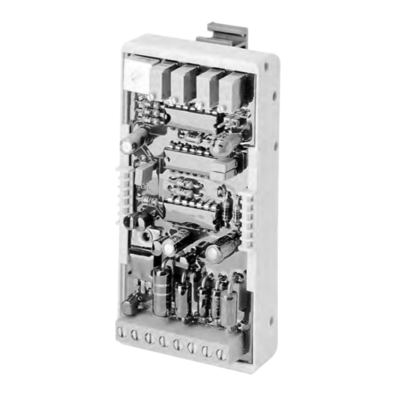
Electronic amplifier type EV1M2-12/24 and EV1M2-24/48
for controlling proportional valves
modular version to be connected via bolt-type terminals, SIL 2 acc. to ISO 61508-1
1.
General
1.1
Brief description and block diagram
The amplifier has a very high control accuracy and can be used to control a
proportional solenoid.
EV1M2-12/24 from 12V DC to 24V DC and EV1 M 2-24/48 from 24V DC to 48V DC.
Main components:
Permanent voltage regulator for generating 5V DC stabilized voltage
linear ramp generator (integrator) with separate adjustment of rise and fall times
dither oscillator
Current-controlled, chopped terminal stage
Main features:
i
and i
standard and maximum current may be precisely adjusted by multi-gear
min
max
potentiometer.
Dither amplitude adjustable, dither frequency either 60 or 120 Hz.
Power supply secured against incorrect pole connection
Output protected against short cut and ground
dither signal superimposed on current output
Enable/disable input (making the ramp ineffective)
Improved EMC (electromagnetic compatibiIity)
In conjunction with the card holder available as an accessory, this printed circuit
with its compact dimensions fits conveniently on to 35 mm or 32 mm support rails in
electric cabinets. Thanks to the modular design the connections on an 8-piece pin bar
are clearly arranged and easily accessible from the front.
The amplifier fulfill Performance level Pl d and Safety integrity level Sil 2
Block diagram
u
nom.
Enable/disable
B4, TP3-TP6 are only in use when a coarse adjustment of the ramp times „rise" and/or „fall" on
the multi-range-potentiometers is carried out by measuring the voltage (see sect. 4.2).
TP1, TP2 test points for measuring the coil (inductive) current 100 mV & 0.5 A (100 mV & 0.2A)
This amplifier may be used for all HAWE proportional valves, see selection table in D 7810 Ü (over-view). With electro-hydraulic
remote control of PSL(V) directional valves as specified in D 7700-..., always make sure due to the twin proportional solenoids used
for switch positions A and B that, depending on the direction of control and activation, there is an automatic, electric switchover
to the respective solenoid, for example by a directional switch (micro-switch) in the remote control hand lever potentiometer, see
typical circuit diagram in sect. 5.2.
For other languages of this document see:
Andere verfügbare Sprachen hier erhältlich:
Pour les autres langues de ce document, voir:
Il documento è disponibile in altre lingue qui:
© 1993 by HAWE Hydraulik
在此可获得其他可用语言版本:
Версии данного документа на других языках см.:
본 문서의 다른 언어 버전은 다음을 참조하십시오:
その他の言語は以下をご参照ください:
Jiné jazyky k dispozici zde:
HAWE HydrAulik SE
STREITFELDSTR. 25 • 81673 MÜNCHEN
up
down
http://www.hawe.de/en/products/by-category/electronics/
Technical support
Phone: + 49 (0) 89 / 37 91 00 - 1256
E-mail: tech-support@hawe.de
1
) Values in brackets valid for
EV1M2-24/48
D 7831/1
Electronic amplifier
November 2011-00
5
Advertisement

Related Manuals for HAWE Hydraulik EV1M2-12/24

Summary of Contents for HAWE Hydraulik EV1M2-12/24
- Page 1 The amplifier has a very high control accuracy and can be used to control a proportional solenoid. EV1M2-12/24 from 12V DC to 24V DC and EV1 M 2-24/48 from 24V DC to 48V DC. Main components: Permanent voltage regulator for generating 5V DC stabilized voltage...
-
Page 2: Specifications
EN 60529 or IEC 529 IP 00 Ambient temperature -20... + 50°C (up to 70°C at 75% of the max. power output I 2.3.2 Electrical data EV1M2-12/24 EV1M2-24/48 Supply voltage 9 ... 32V DC 18 ... 65V DC max. perm. ripple factor w... -
Page 3: Printed Circuit
TP5-6 test points to adjust ramp times (see sect. 4.2) max. 1.8 mm range for securing and moving printed circuit (see also sect. 6.1) ) 100 mV & 0.5 A for EV1M2-12/24 100 mV & 0.2 A for EV1M2-24/48 Plan of terminal connections: B1 - B4 bridges (jumpers) KI. -
Page 4: Instructions For Installation
= Fuse 2.5 A mT at EV1M2-12/24 ramp up time t Fuse 1.6 A mT at EV1M2-24/48... - Page 5 D 7831/1 page 5 Further instructions In the event of interference during the setting procedure or when commissioning, check mains supply. In the case of rectified bridge configuration, check whether anelectrolyte filter capacitor of at least 2200 mF/A coil voltage is switched parallel to the supply voltage.
-
Page 6: Typical Circuits
D 7831/1 page 6 Typical circuits Use of a proportional solenoid to control hydraulic valves Jumper position Target voltage range Example a: Operation with an external target value potentiometer F1 = medium-fast fuse; for nominal see sect. 4.1 . P1 = target value potentiometer 10 kΩ, min 0.1 W Jumber B1 and B2 closed, other bridges open Dither frequency Example b: Operation with a target value switch for the... - Page 7 D 7831/1 page 7 Controlling hydraulic valves using one twin or two individual proportional solenoids for alternating operation Jumper This mode of operation requires a remote-control potentiometer for central B1 + B2 alignment and side recognition of two positively connected direct. switches closed SB 1 and SB 2 for solenoid coils 1 and 2 Example f: Controlling a proportional directional valve type PSL ..