Table of Contents
Advertisement
Product Manual
Product Description
VIGIL AssureCare is a sophisticated emergency call-point system, which has been developed in accordance
with BS5839 part 9 and BS5588. The system is a fully monitored and battery-backed communication network,
and has capabilities to function as a Disabled Refuge System, Emergency Help Point System or a simple Call
Point System.
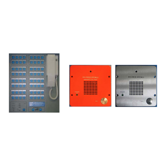
The system has two main components: the Main Control Panel and the Call Point Remote Units. The Main
Control Panel is available in eight options: 16, 32, 48, 64, 80, 96, 112 or 128 way. The panel is normally wall
mounted within a permanently manned main Control Room. There are two versions of Call Point Remote Units
available (red or in stainless steel), which are wall-mounted in areas of risk, such as stairwells, corridors and
'gathering' areas.
In an emergency situation, personnel can press the Call button on a Call Point Remote Unit to call and speak
with a Fire Officer or Building Manager. The Fire Officer or Building Manager uses a press to talk telephone
handset at their dedicated Control Panel(s) to control the half-duplex communication with Call Points on an
'all-call' or individual basis to relay instructions or to provide reassurance.
Slave Control Panels can be added to the system for control of local zones of Call Point Remote Units (e.g. in
a stairwell), and repeater units are available to extend the cabling distance between the Remote Units.
Manual Contents
For the System Maintainer:
For the System User:
Operator's Manual
Document ref.: IBVCP issue 1
IBVCP1
VIGIL AssureCare
1
1
2
2
2
3
10
13
17
20
21
supplied separately
Page 1 of 22
Advertisement
Table of Contents

Summary of Contents for Baldwin Boxall VIGIL AssureCare
-
Page 1: Table Of Contents
VIGIL AssureCare Product Description VIGIL AssureCare is a sophisticated emergency call-point system, which has been developed in accordance with BS5839 part 9 and BS5588. The system is a fully monitored and battery-backed communication network, and has capabilities to function as a Disabled Refuge System, Emergency Help Point System or a simple Call Point System. -
Page 2: Ce Declaration
CE Declaration This equipment is designed and manufactured to conform to the following EC standards: EN 55103-1, Environment E1, EN 55103-2 E5 Safety EN 60065 Failure to install or use the equipment in the manner described in the product literature will invalidate the conformity. -
Page 3: For The System Designer
VIGIL AssureCare utilises a 4-wire plus screen ring circuit to allow continued operation in the event of a cable break. There are typically 20-25 Call Point Remote Units on each circuit (section) of the ring. The maximum... - Page 4 Cabling Design and Installation Recommendations (cont.) Configuration Example 1: 16 Call Point Remote Units This diagram shows an example configuration of 16 Call Point Remote Units (typically 20-25) connected to a Control Panel using one ring circuit. The terminal blocks labelled ‘TB1’ are located in the top of the Control Panel enclosure, and the terminations for Call Point Remote Units 1 and 16 are also shown in detail.
- Page 5 Cabling Design and Installation Recommendations (cont.) Configuration Example 2: FIRST LAST BVCP BVCP BVCP BVCP BVCP BVCP BVCP BVCP BVCP BVCP BVCP BVCP BVCP BVCP Document ref.: IBVCP issue 1 Page 5 of 22...
- Page 6 Cabling Design and Installation Recommendations (cont.) Configuration Example 3: Typical Connection Diagram Up To 48 Units FIRST LAST BVCP BVCP BVCP BVCP BVCP BVCP BVCP BVCP BVCP BVCP BVCP BVCP BVCP BVCP BVCP BVCP BVCP BVCP BVCP BVCP BVCP BVCP Document ref.: IBVCP issue 1 Page 6 of 22...
- Page 7 Cabling Design and Installation Recommendations (cont.) Configuration Example 4: Typical Connection Diagram Up To 64 Units FIRST LAST BVCP BVCP BVCP BVCP BVCP BVCP BVCP BVCP BVCP BVCP BVCP BVCP BVCP BVCP BVCP BVCP BVCP BVCP BVCP BVCP BVCP BVCP BVCP BVCP BVCP...
- Page 8 Cabling Design and Installation Recommendations (cont.) Configuration Example 5: 1300m MAX This diagram shows configuration of a complex system. The configuration uses a Master Control Panel, two Slave Control panels (16Way and 64Way), and serves 89 Call Point Remote Units on a ring consisting of 2200m MAX 10 wiring circuits.
- Page 9 Cabling Design and Installation Recommendations (cont.) Recommended Cable Type The ring circuit must be cabled in a 4-core with screen fire rated cable. FP200, or equivalent, is recommended. MICC can be used, but identification of the individual conductors for correct phasing of conductor pairs (which is essential to prevent damage to the equipment) can be difficult with this type of cable.
-
Page 10: For The Equipment Installer
For the Equipment Installer This section assists the system installer to install the equipment, and terminate and test the cabling. It is assumed that all the cable runs have already been installed according to the system designer’s specification. To install this product you will need; Tools for fixing the control panel on, or flush with, a vertical surface A small flat-bladed screwdriver A large Philips screwdriver for removing/replacing internal screws... - Page 11 4-wire View of cable terminations to Ring OUT Control Unit Termination Panel. Note: In this example, the ring 4-wire consists of one circuit of Call Ring IN Point Remote Units. Note: All data cables must be routed only through the left-hand cut-outs of the cabinet. 52.5 552.0 Diagram Showing Hole Centres For Mounting 128 Zone Control Unit...
- Page 12 Check the cabling Before connecting the Control Panel or Remote Unit electronics to the cabling, check all cabling for correct phasing absence of shorts, etc. It is most important that power is not applied across the data pair or reversed, as this will cause damage to the equipment.
-
Page 13: For The System Commissioner
For the System Commissioner This section assists the system commissioner to check the installation, configure the system, and confirm it is functioning correctly. Commissioning must be carried out on a new system or if a Remote has been added or replaced. To commission this product you will need;... - Page 14 Commission the System (cont.) 2) Install the Call Point Remote Unit electronics sub-assemblies 1. At the rear of the Remote Unit remove the screw to release the bracket retaining the blue termination block. 2. Terminate all cables at the termination block according to the system designer’s specifications and the diagram on the Remote Unit rear panel.
- Page 15 Commission the System (cont.) Then press and release the Fault Accept button to silence the fault buzzer. This sequence will cause the master panel to send a special code around the ring. The green indicators should light as power and data reach each Call Point Remote Unit. If the total number of illuminated indicator’s is the same as the number of Call Point Remote Units on the ring then there are no wiring faults (except possibly between the last Call Point Remote Unit and the master panel).
- Page 16 Commission the System (cont.) Master and Slave(s) Control Panel System Commissioning must be carried out on a new system or if a remote has been added or replaced. If the Slave Control Panel(s) has Call Point Remote Unit ring circuits wired directly to it, then these circuits should be individually tested as described in the previous section.
-
Page 17: How To Use The Zone Insert Labels
Commission the System (cont.) 4) Configure the Control Panel Button Boards (if not already factory-configured) The master panel has one button for each Call Point Remote Unit on the system. Slave panel(s) only need buttons for the Call Point Remote Units that they operate. The panels can be fitted with up to 8 ‘button boards’. Each of these boards has 16 buttons and serves 16 Call Point Remote Units, making a maximum of 128 per Control Panel. - Page 18 Document ref.: IBVCP issue 1 Page 18 of 22...
- Page 19 How to Use the Zone Insert Labels (cont.) Slide the strips cut from the Zone Insert template under the membrane at the positions shown in the picture. They can be inserted from either side. ® Note: Zone Insert Template is also available to download as a Word file from www.baldwinboxall.co.uk Document ref.: IBVCP issue 1 Page 19 of 22...
-
Page 20: System Maintenance And Expansion
For the System Maintainer This section assists the system maintainer to perform preventive maintenance, identify faults, and expand the system. Preventive Maintenance At least once a week, perform a functional test at each Call Point Remote Unit and confirm it can make calls with the Master and Slave Control Panels. -
Page 21: Control Panel Indicators And Controls
Control Panel Indicators and Controls ‘System OK’ LED Illuminates when no faults are detected. Will flash and a beeper will sound when a Fault is detected until “Fault ‘Common Fault’ LED Accept” is pressed. After a fault is accepted the beeper is silenced and the LED remains illuminated until the fault is cleared. - Page 22 Web: www. www.baldwinboxall.co.uk In the interest of continual product development, Baldwin Boxall Communications Ltd. reserves the right to make changes to product specification without notice or liability. Information contained in this document is believed to be accurate, however no representation or warranty is given and Baldwin Boxall Communications Ltd.
- Page 23 VIGIL ASSURECARE Product Description VIGIL AssureCare is a sophisticated emergency call-point system, which has been developed in accordance with BS5839 part 9 and BS5588. The system is a fully monitored and battery-backed communication network, and has capabilities to function as a Disabled Refuge System, Emergency Help Point System or a simple Call Point System.
- Page 24 Operating Instructions for Master and Slave Control Panels If there is more than one control panel on the system the instructions below apply to both panels. It is recommended that only one panel be used at a time to prevent confusion. When a call has been made from a remote unit its status is ‘occupied’, and the Control Panel green indicator for that unit is illuminated.
- Page 25 Operating Instructions for Remote Refuge Units To initiate a call to a Control Panel, press the CALL button. The Remote Unit will ‘ring’ and so will the handset(s) at the Control Panel(s). When the person at the control panel answers, wait for them to finish speaking before trying to speak back –...
- Page 26 Web: www. www.baldwinboxall.co.uk In the interest of continual product development, Baldwin Boxall Communications Ltd. reserves the right to make changes to product specification without notice or liability. Information contained in this document is believed to be accurate, however no representation or warranty is given and Baldwin Boxall Communications Ltd.
- Page 27 ADDENDUM CommuniCare Advance & AssureCare Fire Panel Interface The CommuniCare Advance and AssureCare Control Panels require an Input from a Fire Panel before allowing conversations between the Remote Units and the Panel. The Connections should be made as follows: To ensure correct operation both JP1 and JP2 must be fitted. If the fire panel connections (or the Test connections to the Break Glass Unit) are not in place the System will Commission correctly but the Control Panel will not allow communication with Remote Units.
Need help?
Do you have a question about the VIGIL AssureCare and is the answer not in the manual?
Questions and answers