
Summary of Contents for Datasensor BWS-T2 Series
- Page 1 DATASENSOR BWS-T2 SERIES Multiray safety barrier, level 2, 1 … 2 pairs of photocells INSTRUCTION MANUAL...
- Page 2 Fax: +39 051 6759324 http://www.datasensor.com e-mail: info@datasensor.com Monte San Pietro, 02/01/2001 DATASENSOR S.p.A. reserves the right to make modifications and improvements without prior notification. Gianni Stradiotti DATASENSOR S.p.A. si riserva il diritto di apportare modifiche e/o miglioramenti senza preavviso. UNI EN ISO 14001 826190024 Rev.E...
-
Page 3: Table Of Contents
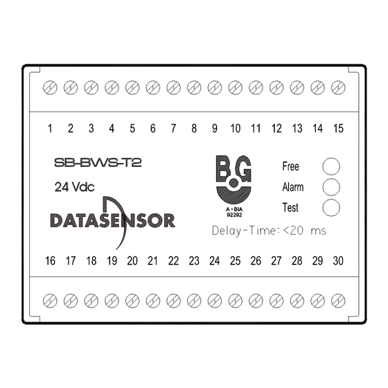
BWS-T2 Series Instructions manual INDEX INTRODUCTION ................2 1.1. OPERATING DESCRIPTION ................5 INSTALLATION................. 9 MOUNTING THE BWS-T2................9 START SWITCH....................9 SENSORS.......................10 SAFETY DISTANCE..................11 2.4.1. PROTECTION OF DANGER ZONES WITH BWS-T2 FOR PROTECTION OF FINGERS AND HANDS ........11 2.4.2. PROTECTION OF ACCESS WITH BWS-T2 - 1- OR MORE BEAMS FOR ARM AND BODY PROTECTION ....12... - Page 4 BWS-T2 Series Instructions manual GENERAL VIEW Figure A...
-
Page 5: Introduction
BWS-T2 Series Instructions manual 1. INTRODUCTION The BWS-T2 is an essential part of a photoelectric installation whose purpose is to maintain a safe environment in potentially dangerous areas where electrical machinery or equipment is in operation. It performs this task by not allowing such machinery to start up unless the dangerous area is clear of any persons or objects. - Page 6 BWS-T2 Series Instructions manual • Machinery for wood treatment prEN691 General requirements prEN859 Planing and straightening machinery with manual transport prEN860 Single sided machinery for planing prEN861 Machinery for combined planing and straightening prEN1807 Band- saws prEN848 Table milling machinery...
- Page 7 BWS-T2 Series Instructions manual EN 811: Oktober 1992 Safety of machinery - Safety distances to prevent danger zones being reached by the lower limbs EN 999: Januar 1995 Safety of machinery - The positioning of protective equipment in respect of approach of parts of the human body EN 954 Part 1: März 1997...
-
Page 8: Operating Description
BWS-T2 Series Instructions manual The BWS-T2 is rated as a type 2 ESPD (Electro Sensitive Protective Device) according to the EUROPEAN STANDARD. A type 2 ESPD is a device which relies on the correct response to external tests to maintain its safety integrity. The device may not detect failures in system integrity between tests. - Page 9 BWS-T2 Series Instructions manual The flow chart on the following page can be used to describe the operation of the BWS-T2: BWS-T2 OPERATION Q Q Q Q Power on Output-Contact Open Start Activated R R R R Initial Test U U U U...
- Page 10 BWS-T2 Series Instructions manual Upon application of power, the red ALARM LED lights up and the START INTERLOCK function will prevent the operation of the output contacts. The active operation mode can be initiated only with a N.O. (normally open) start switch. After closing the start switch, the INITIAL TEST function will be activated automatically.
- Page 11 BWS-T2 Series Instructions manual There are two ways to connect the Test 1 and Test 2 contacts: a) CYCLE TEST procedure using 2 N.C. contacts. TEST1 TEST2 Figure 2 When the Test 1 contact opens, the test procedure begins. When the Test 2 contact opens and closes again, the test procedure ends.
-
Page 12: Installation
BWS-T2 Series Instructions manual 2. INSTALLATION MOUNTING THE BWS-T2 The BWS-T2 must be mounted in an enclosure with at least an IP54 rating. The dimensions of the BWS-T2 are given in the following diagram for mounting purposes: Figure 4 START SWITCH... -
Page 13: Sensors
BWS-T2 Series Instructions manual SENSORS The photoelectric sensors must be mounted in front of the danger area (as per EN 999) so as to protect the entire danger area. The sensors must be installed in the vicinity of the operating equipment in such a way as to allow ENTRY or OPERATION of the machine ONLY THROUGH the safety barrier. -
Page 14: Protection Of Danger Zones With Bws-T2 For Protection Of Fingers And Hands
BWS-T2 Series Instructions manual Danger zone Figure 5 S = V * T+C C=8(d-14mm) Minimum distance - safety distance Approaching speed Delay time of the complete system Supposed length of a part of a body with ∅ < resolution of fotocell array, that exceeds the protecting area without a guaranteed detection. -
Page 15: Protection Of Access With Bws-T2 - 1- Or More Beams For Arm And Body Protection
BWS-T2 Series Instructions manual 2.4.2. Protection of access with BWS-T2 - 1- or more beams for arm and body protection Condition 40mm<d 70mm; C 0 S=1600*T+850mm Mounting hight of the emitter(s) and reiceiver(s): 1 Pair E/R: 750mm 2 Pairs E/R: 400mm, 900mm... - Page 16 BWS-T2 Series Instructions manual INCORRECT INSTALLATION Figure 6a CORRECT INSTALLATION Figure 6b reflecting surface reflecting surface S5 or S10 Figure 7a Figure 7b...
-
Page 17: Photoelectric Sensor Installation
BWS-T2 Series Instructions manual PHOTOELECTRIC SENSOR INSTALLATION When mounting the sensors (emitter(E)/receiver(R) pairs) to the BWS- T2, care must be taken to position these components in such a way as not to interfere with each other. (including with the help of a mirror, see figure 8b and 8c). -
Page 18: Alignment Of The Sensors
BWS-T2 Series Instructions manual Figures 9a-9b show the proper disposition of these elements. Figure 9a Figure 9b ALIGNMENT OF THE SENSOR(S) To align the sensor(s), you have to bridge the start switch from terminal 19 to terminal 20. Using the Receiver output LED of the photoelectric sensor(s) you can align the light barrier. -
Page 19: Electrical Connections
BWS-T2 Series Instructions manual 3. ELECTRICAL CONNECTIONS The BWS-T2 controller provides for the following connections: Signal Terminal Output 1 14; 29 Output 2 15; 30 Start 19; 20 Test 1 Test 2 Emitter 1 5;6;7;8 Receiver 1 21;22;23;24 Emitter 2 25;26;27;28... - Page 20 BWS-T2 Series Instructions manual max. 220 VAC EMITTER RECEIVER TEST1 TEST2 FUSE 10 11 SB-BW S-T2 17 18 19 20 21 23 24 25 START User tool User tool VOLTAGE SUPPLY 24 V + 10 % EL. CONTROL CABINET Figure 10 - One Emitter/Receiver pair...
- Page 21 BWS-T2 Series Instructions manual EMITTER RECEIVER max. 220 VAC TEST1 TEST2 FUSE 10 11 SB-BW S-T2 17 18 19 20 21 23 24 25 User tool User tool START EL. CONTROL CABINET VOLTAGE SUPPLY 24 V + 10 % Figure 11 - One Emitter/Receiver pair...
- Page 22 BWS-T2 Series Instructions manual EMITTER RECEIVER TEST1 TEST2 10 11 SB-BW S-T2 17 18 19 20 21 23 24 25 VOLTAGE SUPPLY 24 V + 10 % RECEIVER EMITTER Figure 12 - Two Emitter/Receiver pairs When operating with 2 E-R pairs, the wiring configuration shown in figure 12 must be respected.
- Page 23 BWS-T2 Series Instructions manual The maximum specified rating of the BWS-T2 output contacts must not be exceeded. With inductive loads, arc suppression or switching as described below should be utilized. For user tools that require load currents that exceed the BWS-T2 contact rating, auxiliary power operated switches must be used (see figure 13).
-
Page 24: Technical Data
BWS-T2 Series Instructions manual 4. TECHNICAL DATA Voltage: 24 Vdc ± 10%, reverse polarity protection Max Power Consumption: (1 Emitter-Receiver pair) 3.4 W (2 Emitter-Receiver pair) 3.8 W Weight: 510 g. (without sensors) Operating Temperature: 0…50 °C Output: (SDS safety relay) - Page 25 BWS-T2 Series Instructions manual Specifications related to the photoelectric sensors Type Emitter S5-5-G8-60-ST2 S10-5-G8-60-ST2 S30-5-G50-1-ST2 S5-5-G8-62-ST2 S10-5-G8-62-ST2 S30-5-G50-2-ST2 Receiver S5-5-F8-90-ST2 S10-5-F8-90-ST2 S30-5-F50-1-ST2 (Light pulse PNP S5-5-F8-92-ST2 S10-5-F8-92-ST2 S30-5-F50-2P-ST2 output) select light pulse! Max. sensing 50 m distance Min. object class ∅...
Need help?
Do you have a question about the BWS-T2 Series and is the answer not in the manual?
Questions and answers