Table of Contents
Advertisement
Advertisement
Table of Contents

Subscribe to Our Youtube Channel
Related Manuals for EGi Geodesic Photogrammetry System


Summary of Contents for EGi Geodesic Photogrammetry System
- Page 2 Please check EGI's regulatory clearances or contact EGI to get the current regulatory status of EGI products in your country. This manual is not an offer to sell a medical device in any country where its sale would be prohibited by national law.
- Page 3 Geodesic Photogrammetry System (GPS) Sensor Localization System version 3.1.2 User Manual GPS 3 User Manual | 8103002-56 • 2018-07-17...
- Page 4 Key changes in this revision: • Section 1.1: Revised Intended Use. • Section 3.2: Added System Requirement for “Silver Dot” GSNs. • Section 4.1.1: Added information on sensor label types. • Section 4.3: Updated Exposure control instructions. GPS 3 User Manual | 8103002-56 • 2018-07-17...
-
Page 5: Table Of Contents
Contents Preface 1. Safety and Use Conditions Intended Use Features Conditions for Use Safety Warnings 2. GPS Hardware Components 2.1.1 Dome 2.1.2 Gantry 2.1.3 Calibration Object 2.1.4 Computer and Monitor 2.1.5 Isolation Transformer Connections Raising and Lowering the Dome Moving the GPS 2.4.1 Dome Lowered and Attached 2.4.2... - Page 6 4. Image Acquisition Before Capturing Images 4.1.1 Imaging Guidelines 4.1.2 Positioning the Patient GPS Acquisition 4.2.1 Menu Bar 4.2.2 Capture Images Window Capturing Images 5. Sensor Modeling GPS Solver Menu Bar 5.1.1 File > Import or Export 5.1.2 File > Reset Solution 5.1.3 File >...
-
Page 7: Preface
NOT ALL SYSTEM OR SOFTWARE FEATURES ARE AVAILABLE FOR PURCHASE OR USE IN ALL COUNTRIES OR MARKETS. For all safety and use conditions for using your EGI system, refer to the manuals and instructions that shipped with your GES system configuration. -
Page 8: About This Manual
EEG systems. Note that the term patient is used to refer to subjects, participants, or patients. An EGI support or authorized engineer will install and configure your EGI system, including all connections required for its operation. At the time of initial installation, the EGI support or authorized engineer will also train relevant staff in its operation. - Page 9 Support, Repairs, and Documentation Electronic copies of EGI’s user manuals and instructions are provided under the Training and Technical Support tab of www.egi.com. If you have a question, please: • For urgent issues during acquisition, contact EGI immediately. • For nonurgent issues, do the following before contacting EGI: –...
- Page 10 GPS 3 User Manual | 8103002-56 • 2018-07-17...
-
Page 11: Safety And Use Conditions
1. Safety and Use Conditions For all safety and use conditions for using your EGI system, refer to the manuals and instructions that shipped with your system configuration. Do not operate your GES system, including the GPS, until you are fully trained and understand all warnings, cautions, and conditions for use provided in EGI’s manuals for the components of your system. -
Page 12: Features
Features • Simultaneous image capture and saving • Minimal patient time requirement • Flexible workflow for technicians • High accuracy—the 3D photographic technique of the GPS minimizes human error and environmental sensitivities inherent in stylus-based methods • Semi-automated identification of sensors using image analysis •... -
Page 13: Conditions For Use
Table 1-2. Site requirements for the location and use of the GPS Location For indoor use only; in or adjacent to the room containing the EGI EEG data acquisition system Area 102 x 150 cm (40 x 59 in.) Ceiling height 221 cm (87 in.) - Page 14 No contraindications for the use of GPSs are known to exist. 1.3.5 Certifications and Classifications For all current EGI regulatory certifications, including CE declarations, go to www.egi.com or contact EGI Technical Support (Table P-1). This medical equipment is certified to the following: •...
- Page 15 • IEC 60601-1-6:2006 Medical electrical equipment, Part 1-6: General requirements for basic safety and essential performance - Collateral standard: Usability • EN 60601-2-2007 Class A Medical electrical equipment - Part 1-2: General requirements for basic safety and essential performance – Collateral standard: Electromagnetic compatibility - Requirements and tests<=""...
- Page 16 • Connect the equipment to an outlet on a different circuit than the one used by the other devices. • Consult EGI Technical Support (Table P-1). 1.3.8 Symbols The following symbols are used on GPS components or in this manual.
-
Page 17: Safety Warnings
GPS components to the isolation transformer or to other GPS components. All system components must be installed and configured by an EGI support or authorized engineer. Deviating from the supported configurations or running the system with non-GPS components attached may result in unexpected hazards or performance due to additional loading or leakage. - Page 18 If liquids are spilled on any GPS electronic component, immediately disconnect it from its power source. Do not use a GPS that has suffered exposure to liquids until EGI or other GPS 3 User Manual | 8103002-56 • 2018-07-17...
- Page 19 • Do not use the system if it has been damaged, unless it has been verified that the system is working correctly. • Only EGI support or authorized engineers may service this equipment. Hazardous mains voltage inside. Refer all servicing to your EGI support or authorized engineer.
- Page 20 • Maintain patient isolation within patient environment. Never simultaneously touch the patient and any component outside of the patient area and never let patients touch any component, other than the Net that is being worn, inside or outside of the patient area. 1.4.3 Moving Warnings WARNING: The GPS weighs 100 kg (220 lb.).
- Page 21 • Use only approved power connections and never connect a non-GPS power cord or multiple socket outlet (i.e., power strip or extension cord) to the GPS. Use only the EGI-approved power cords, connectors, cables, adapters, and multiple socket outlet that came with the GPS.
- Page 22 • Do not open and attempt to fix the GPS. The interior of the GPS contains no user-serviceable parts. In the event that the GPS requires servicing, contact EGI Technical Support (Table P-1). • Do not touch the power supply. The control box houses the power supply.
- Page 23 • Clean the external surface (except the camera lenses) with a cloth that is lightly soaked with lukewarm water and a gentle detergent based on a neutral soap. • Dry with a clean, dry, lint-free cloth. GPS 3 User Manual | 8103002-56 • 2018-07-17...
- Page 24 GPS 3 User Manual | 8103002-56 • 2018-07-17...
-
Page 25: Gps Hardware
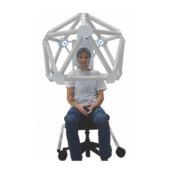
2. GPS Hardware The GPS hardware includes a geodesic dome attached to a counterbalanced gantry, which lifts and lowers the dome over a patient wearing a GSN. The dome is in the shape of an icosahedron (with the bottom removed) with a high-resolution, high-sensitivity camera mounted at each of the 11 remaining vertices. - Page 26 the 11 vertices holds a circuit board with a mounted camera, a USB interface, and a ring of high-intensity white LEDs. While the cameras are not numbered on the dome, the camera- numbering scheme is as follows. Also shown in figures 2-1 and 2-2. •...
-
Page 27: Gantry
2.1.1.1 Cameras The GPS uses 11 cameras to acquire images of sensor positions. The camera lenses have very low radial distortion, typically less than one pixel over the field of view. The cameras are defined by 11 radial parameters: • camera location (radius, theta, and phi) •... -
Page 28: Calibration Object
Figure 2-3. GPS dome and gantry’s components, dimensions, and weights 2.1.3 Calibration Object The GPS will be calibrated for you by EGI’s support engineers at the time of initial installation. Calibration is typically required only once, right after system installation. However, the system should be recalibrated (see Appendix B, “GPS Calibration) if you:... -
Page 29: Computer And Monitor
The calibration object and its stand are shipped unassembled. When needed, simply mount the object onto the stand. The calibration object has 36 total numbered targets of which 11 are camera targets that should point toward their respective cameras (cameras 1 through 11) when positioned in the dome. Figure 2-4. -
Page 30: Connections
is to provide isolation from ground for all GPS components, which must be plugged into it. As a result, if a person inadvertently comes into contact with these components and an electrical potential, the transformer will prevent current flowing from these components through the person’s body to ground. - Page 31 exits the control box (and passes down and out the same cable channel), then plugs into the isolation transformer. Remember that all power connections are routed through the isolation transformer. CAUTION: Do not plug the GPS USB cable into another USB hub, before plugging it into the GPS computer.
-
Page 32: Raising And Lowering The Dome
Raising and Lowering the Dome The upper gantry has two handle bars for safely and smoothly raising and lowering the dome during use. To seat and adjust the height of the dome for each patient, see Figure 2-6 and do the following: Hand loosen the upper gantry’s locking handle counterclockwise about two turns. -
Page 33: Moving The Gps
Moving the GPS Since the GPS is sized to fit through 88.9 cm (35 in.) doorways, there may never be a need to remove the dome from the gantry. In most cases, you will be able to move the GPS with the dome in its normal position or, in rare cases, rotated. -
Page 34: Dome Lowered And Attached
2.4.1 Dome Lowered and Attached Use this procedure when moving the GPS within the same building with doorways greater than 102 cm (40 in.). If you are moving the GPS to another building or if your doorways are unusually narrow, it is recommended that you rotate (section 2.4.2) or remove (section 2.4.3) the dome. -
Page 35: Dome Lowered And Rotated
From behind the gantry, hold both handle bars on the upper gantry and push the GPS forward. Have someone bring along the patient chair, or bring it separately. 2.4.1.3 Set Up the GPS When at the GPS’s new location, do the following: Lock all four casters. - Page 36 On the isolation transformer, turn off the mains power supply by flipping the mains disconnect switch to OFF ( O ). Unplug all GPS cables (data and power) and safely secure them. Hand loosen the upper gantry’s locking handle counterclockwise about two turns. From behind the gantry, hold both handle bars on the upper gantry and manually lower the upper gantry and dome to the bottom stop.
- Page 37 For added safety, have a second person hold the dome to ensure it remains in its rotated position. 2.4.2.3 Move the GPS Unlock all four casters. From behind the gantry, hold both handle bars on the upper gantry and push the GPS forward. Have someone bring along the patient chair, or bring it separately.
-
Page 38: Dome Lowered And Removed
2.4.3 Dome Lowered and Removed Use this procedure only if you Tools needed (not provided): are moving the GPS to another • 3/8-inch Hex socket nut driver building or if your doorways are • T15 Torx screwdriver narrower than 90 cm (35 in.). •... - Page 39 2.4.3.2 Disconnect Internal Wiring You will be working inside the control box. Figure 2-8. Inside the control box of the GPS Using the T15 Torx screwdriver, remove the cover of the control box. It is attached between the 4/5/9 camera triad. Carefully pry off the screw caps that cover the screws at the four...
- Page 40 Using the 3/8-inch Hex socket nut driver, release the two ground wires— the power cord and the upper frame ground wires: Remove each nut from the grounding post. Lift each ground wire off the grounding post. Unplug the two cables from the bottom of the USB hub—the USB-to-PC and power cables.
- Page 41 Unplug the input cord from the power supply. Using the 5/32-inch Hex L-wrench, remove the screw from the cable tie- down located near the cable pass- through hole. Notice that the cable tie-down is a cushioned cable clamp. GPS 3 User Manual | 8103002-56 • 2018-07-17...
- Page 42 Push the cables that are surrounded by the cushioned clamp (that is, the USB’s power and PC cables and the power supply’s power cable) through the hole and into the dome rotation bracket. 2.4.3.3 Remove the Dome and Move the GPS Using the 5/32-inch Hex L-wrench, loosen each set screw in each dome...
- Page 43 Carefully lift the dome up and off of the dome rotation bracket. Use two people, if needed. The dome weighs 15 kg (32 lb.). Safely load the dome onto a transport cart. 2.4.3.4 Move the GPS Unlock all four casters. From behind the gantry, hold both handle bars on the upper gantry and push the GPS forward.
- Page 44 GPS 3 User Manual | 8103002-56 • 2018-07-17...
-
Page 45: Gps Software
3. GPS Software GPS Acquisition and GPS Solver The GPS software consists of two applications: • GPS Acquisition (formerly, Net Local) image capturing software. Along with the GPS dome of 11 cameras, precisely photographs where sensors are located on the head. •... -
Page 46: System Requirements
The GPS Acquisition image capturing software and the GPS Solver sensor modeling software come installed on the EGI system computer. If you need to update the version or reinstall the software, contact EGI Technical Support (Table P-1) for a download link. -
Page 47: Image Acquisition
4. Image Acquisition It takes only minutes for the GPS to acquire the photographic images that provide all the information necessary to register sensor positions. The sensor positions are then modeled after the patient is released. Before Capturing Images 4.1.1 Imaging Guidelines To acquire usable photographic images, do the following:... -
Page 48: Positioning The Patient
• Ensure that the patient’s preauricular points—the indentations in front of the earflaps where the jaw meets the skull—are visible. • Ensure that the patient sits still and is centered within the GPS dome. Adjust the patient’s position and/or the dome’s height as needed. -
Page 49: Gps Acquisition
GPS Acquisition The GPS Acquisition software is used only for image capturing. All other sensor registration operations are performed within the GPS Solver sensor modeling software. 4.2.1 Menu Bar The standard controls of the GPS Acquisition menu bar operate as expected. If the GPS is not connected to the computer, no menus will appear. - Page 50 Figure 5-1. GPS Acquisition’s Capture Images window GPS 3 User Manual | 8103002-56 • 2018-07-17...
- Page 51 Table 5-1. Capture Images commands Callout Command Description Live When selected, the system streams real-time live video. The Capture Images window opens in this mode. This button is used to restart live streaming, after having captured still images with the Capture button, if you need to adjust the patient (or calibration object) for better images.
-
Page 52: Capturing Images
Capturing Images To capture images of a patient wearing a GSN, adhere to all of the guidelines of this chapter, see Figure 5-2, and do the following: WARNING: Moving parts are a pinch-and-crush hazard. When adjusting the GPS dome to accommodate a patient’s height and/or position, keep all clothing, hair, and body parts well away from moving parts. - Page 53 In the Net Local window, do the following: • Select the correct Net, which automatically updates the Number of Sensors, Pedestal Height, and GPS Number fields. • Add the patient’s information. Again, all patient fields are required and accept alphanumeric and special characters.
- Page 54 Click Capture. The streaming video will be stopped. Review the still images and: • If acceptable, click Save Images and proceed to step 9. • If unacceptable, click Live to restart the streaming of live video and readjust the patient’s position and/or dome’s height.
- Page 55 GPS 3 User Manual | 8103002-56 • 2018-07-17...
-
Page 56: Sensor Modeling
5. Sensor Modeling With continuous feedback, the GPS Solver sensor modeling software semi-automatically identifies the sensors and analyzes their locations in each photograph. Only a minimum of interaction is needed to adjust sensors for maximum accuracy. With experience, modeling the sensors in a 256-channel Net takes 15 to 20 minutes. -
Page 57: File > Reset Solution
EMSE .nsi if using Net Station 4.5.7 or later Note that a GeoScan .txt file cannot be taken directly into Net Station or GeoSource—it must be converted into EGI’s coordinates.xml format, first. GPS 3 User Manual | 8103002-56 • 2018-07-17... - Page 58 To use the GeoScan file batch converter: Drop a file or folder containing files into the file drop pane. For each file, select the desired export file format. For each file, select the correct Net Type. Select whether or not to save the exported files to the input directory(s) or other directory(s).
-
Page 59: Settings > Confirm Identification
5.1.4 Settings > Confirm Identification From the Settings menu, you can control whether or not the software prompts you with a confirmation dialog after each sensor you mark. 5.1.5 Calibration > Open Calibration The Calibration menu options are used during calibration, not acquisition or solving. -
Page 60: Identify Sensors
Verify the file’s information and confirm that the software shows the correct GSN type. If needed, select the correct GSN under Net Type. 5.2.2 Identify Sensors Before the GPS Solver can semi-automatically analyze and locate sensors, it will ask you to identify one sensor in each camera view, always starting with camera view 1. - Page 61 To identify sensors: In this example, GPS Solver is prompting you to click sensor 8 in camera view 1. a) Click the center black dot, which corresponds to the electrode below it. b) Click Yes or No to confirm the location you clicked in step 1a.
-
Page 62: Verify Sensor Placement
Wait for GPS Solver to finish updating the sensor corrections. Besides the changes occurring in the 3D model view, you will see a “Please wait a moment” message at the top of the screen and a “Detecting sensors” message next to the green progress bar at the bottom of the screen. - Page 63 To verify sensors: Click camera 1 in the camera grid. You will find it easier to track your progress if you work on the cameras in numerical order. In the right-hand, 2D image, look for all transparent blue labels that are misaligned from their corresponding sensors in the photo.
- Page 64 After aligning all blue labels and sensors in the 2D model view for a camera view, click Verify Sensor Placement. Continue aligning the blue labels and sensors in all 11 photos. As you continue aligning blue labels over sensors in the 2D model view, notice that the software continues verifying and reverifying their alignment with their neighbor sensors with each label you move.
-
Page 65: Adjust Sensors
If too many sensors are red, or if any have a questionably high Sensor Error, you can verify your system’s calibration. With only 36 targets, this process is quick. Here are the highlights but, for details, contact EGI Technical Support (Table P-1): o Solve the calibration object to verify the GPS’s calibration: 1. -
Page 66: Specify The Fiducials (Nasion, Lpa, And Rpa)
If unsure, contact EGI Technical Support (Table P-1). • The sensor should now turn green. If it doesn’t, contact EGI Technical Support (Table P-1). After all sensors have turned green, rotate through the 3D model view to make sure nothing was missed. -
Page 67: Save
Once placed, fiducials can be adjusted but cannot be removed. 5.2.6 Save After the Status pane shows all stages are checked as completed, save your file: • File > Save As • Close (red button) > Yes (Save changes? Dialog) Remember that it is not uncommon for a few sensors to not turn green. -
Page 68: Data Exporting
6. Data Exporting At any time after solving your file, you can export a solution file from GPS Solver that you can embed into your data file. The following export formats embed into the given data formats: GPS Solver export file formats Data formats .xml .sfp... -
Page 69: Embedding A .Xml Export Into An Mff Data File
Embedding a .xml Export into an MFF Data File Exporting your solved file with the MFF option gives you the coordinates of sensor positions in a format (i.e., .xml) that you can manually place into your MFF file’s package contents. Once a coordinates.xml file is placed into an EEG file’s package contents, there is no confirmation. - Page 70 Notice that the EEG file’s package contents already contains a coordinates.xml file. Drag and drop the new coordinates.xml file into the EEG file’s package contents and click Replace. GPS 3 User Manual | 8103002-56 • 2018-07-17...
- Page 71 GPS 3 User Manual | 8103002-56 • 2018-07-17...
-
Page 72: Appendix A: Gsn Sensor Layouts
Appendix A: GSN Sensor Layouts If needed, use these sensor layouts for reference. Figure A-1. 32-channel GSN sensor layout GPS 3 User Manual | 8103002-56 • 2018-07-17... - Page 73 Figure A-2. 64-channel GSN sensor layout GPS 3 User Manual | 8103002-56 • 2018-07-17...
- Page 74 Figure A-3. 128-channel GSN sensor layout GPS 3 User Manual | 8103002-56 • 2018-07-17...
- Page 75 Figure A-4. 256-channel GSN sensor layout GPS 3 User Manual | 8103002-56 • 2018-07-17...
-
Page 76: Appendix B: Gps Calibration
Along with all the hardware, software, operational connections, and training required for operation, the GPS will be calibrated for you by EGI’s support engineers at the time of initial installation. Calibration is typically required only once, right after system installation. However, the system should be recalibrated if you: •... - Page 77 Secure the GPS and Set Up the Calibration Object To acquire images for calibration, use the GPS Acquisition software and do the following. WARNING: Moving parts are a pinch-and-crush hazard. When adjusting the GPS dome, keep all clothing, hair, and body parts well away from moving parts to prevent injury.
- Page 78 Capture Images Start the GPS Acquisition image capturing software by clicking the GPS Acquisition icon. In the Technician Info window, add your information, then click OK. All fields are required and accept alphanumeric and special characters. In the GPS Acquisition window, do the following: a) Select the calibration object.
- Page 79 b) all targets are pointing toward their corresponding cameras (see Appendix C); c) all targets are visible in at least two views; and d) no targets are obstructed by glare or angle. Adjust the Exposure slider as needed to control any brightness and/or glare in the images.
- Page 80 Calibrating the System by Modeling the Calibration Targets Aligning the locations of calibration targets differs from that of sensors as follows: • Modeling the calibration targets actually calibrates the system rather than creating a file of sensor locations. • There is no initial guided identification of a target in each camera view.
- Page 81 blue Align the projected target labels with the object’s targets in all 11 camera images. Use the camera grid to cycle through the 11 camera images. After the Status pane shows all stages are checked as completed, select Calibration > Calibrate.
- Page 82 After calibration is complete, check the reprojection error in the status bar. This reprojection error of the calibration object is based on the new calibration parameters and should be below 2.0 mm. Calibration Succeeded. Camera calibration files saved. Reprojection Error: 0.3224379970098484 •...
- Page 83 Verify that the reprojection error is now below 2.0 mm. If you have any issues, contact EGI Technical Support (Table P-1). GPS 3 User Manual | 8103002-56 • 2018-07-17...
-
Page 84: Appendix C: Calibration Object Target Layouts
Appendix C: Calibration Object Target Layouts If needed, use these target layouts for reference. These layouts show which targets should be visible on the calibration object in each camera view. Figure C-1. Camera view 1 showing targets 1, 2, 3, 4, 5, 6, 12, 13, 14, 15, 16, 17, 18, 19, 20, and 21 GPS 3 User Manual | 8103002-56 •... - Page 85 Figure C-2. Camera view 2 showing targets 1, 2, 3, 6, 7, 11, 12, 13, 16, 17, 21, 22, 23, 30, 31, and 36 Figure C-3. Camera view 3 showing targets 1, 2, 3, 4, 7, 8, 12, 13, 14, 17, 18, 22, 23, 24, 25, and 32 GPS 3 User Manual | 8103002-56 •...
- Page 86 Figure C-4. Camera view 4 showing targets 1, 3, 4, 5, 8, 9, 13, 14, 15, 18, 19, 24, 25, 26, 27, and 33 Figure C-5. Camera view 5 showing targets 1, 4, 5, 6, 9, 10, 14, 15, 16, 19, 20, 26, 27, 28, 29, and 34 GPS 3 User Manual | 8103002-56 •...
- Page 87 Figure C-6. Camera view 6 showing targets 1, 2, 5, 6, 10, 11, 12, 15, 16, 20, 21, 28, 29, 30, 31, and 35 Figure C-7. Camera view 7 showing targets 2, 3, 7, 8, 11, 17, 22, 23, 24, 31, 32, and 36 GPS 3 User Manual | 8103002-56 •...
- Page 88 Figure C-8. Camera view 8 showing targets 3, 4, 7, 8, 9, 18, 23, 24, 25, 26, 32, and 33 Figure C-9. Camera view 9 showing targets 4, 5, 8, 9, 10, 19, 25, 26, 27, 28, 33, and 34 GPS 3 User Manual | 8103002-56 •...
- Page 89 Figure C-10. Camera view 10 showing targets 5, 6, 9, 10, 11, 20, 27, 28, 29, 30, 34, and 35 Figure C-11. Camera view 11 showing targets 2, 6, 7, 10, 11, 21, 22, 29, 30, 31, 35, and 36 GPS 3 User Manual | 8103002-56 •...
-
Page 90: Appendix D: Emc Declarations
Note that portable and mobile RF communications equipment can affect GPSs. WARNING: The use of accessories and cables other than those sold by EGI may result in increased emissions or decreased immunity of the GPS. WARNING: EGI equipment should not be used adjacent to or stacked with other equipment. -
Page 91: Electromagnetic Emissions
Electromagnetic Emissions Table D-1. Electromagnetic compatibility (EMC) emissions guidelines and declarations for GPSs GPSs are intended for use in the electromagnetic environment specified below. The customer or user of a GPS should ensure that it is used in such an environment. Electromagnetic Environment—... - Page 92 Electromagnetic Immunity Table D-2. Electromagnetic compatibility (EMC) immunity guidelines and declarations for GPSs GPSs are intended for use in the electromagnetic environment specified below. The customer or user of a GPS should ensure that it is used in such an environment. IEC 60601 Test Compliance Electromagnetic...
- Page 93 IEC 60601 Test Compliance Electromagnetic Immunity Test Level Level Environment—Guidance 3 A/m 3 A/m Power Power frequency magnetic frequency fields should be at levels (50/60 Hz) characteristic of a typical magnetic field location in a typical IEC 61000-4-8 commercial or hospital environment.
- Page 94 Electromagnetic Immunity for Non-life- supporting Equipment Table D-3. Electromagnetic compatibility (EMC) immunity guidelines and declarations for non- life-supporting equipment (such as GPS components) GPSs are intended for use in the electromagnetic environment specified below. The customer or user of a GPS should ensure that it is used in such an environment. Immunity IEC 60601 Compliance...
- Page 95 Immunity IEC 60601 Compliance Electromagnetic Test Test Level Level Environment—Guidance Note 1: At 80 MHz and 800 MHz, the higher frequency range applies. Note 2: These guidelines may not apply in all situations. Electromagnetic propagation is affected by absorption and reflection from structures, objects, and people.
-
Page 96: Recommended Separation Distances
Recommended Separation Distances Between Radio-frequency (RF) Communications Equipment Table D-4. Recommended separation distances between RF communications equipment (portable and mobile) and GPS components GPSs are intended for use in an electromagnetic environment in which radiated RF disturbances are controlled. The customer or user of a GPS can help prevent electromagnetic interference by maintaining a minimum distance between portable and mobile RF communications equipment (transmitters) and GPS components as recommended below, according to the maximum output power of the... - Page 97 GPS 3 User Manual | 8103002-56 • 2018-07-17...
- Page 98 GPS 3 User Manual | 8103002-56 • 2018-07-17...
Need help?
Do you have a question about the Geodesic Photogrammetry System and is the answer not in the manual?
Questions and answers