Table of Contents
Advertisement
Quick Links
Introduction ........................................................................................................................................................ 1
Display/Keyboard operation: Summary ............................................................................................................. 1
Programming Joule Alarm ................................................................................................................................. 2
Controlled outputs .......................................................................................................................................... 2
LED Display programmable settings architecture.......................................................................................... 2
Example 1. Programming a room using the keyboard settings ..................................................................... 2
Main Settings [AA1 Keypad menu] ................................................................................................................ 4
Advanced Settings [AA2 Keypad menu] ........................................................................................................ 4
Maintenance Settings [LOD Keypad menu]................................................................................................... 4
Browser Interface - Joule Alarm Standard Web pages ..................................................................................... 4
Example 2. Programming a Fruit Room......................................................................................................... 5
Main Page ...................................................................................................................................................... 5
Channel Options......................................................................................................................................... 6
Control Buttons........................................................................................................................................... 6
Logs............................................................................................................................................................ 6
Log Control Buttons.................................................................................................................................... 6
Graph.......................................................................................................................................................... 7
Graph Legend ............................................................................................................................................ 7
Settings Page................................................................................................................................................. 7
Normal Settings.............................................................................................................................................. 7
General Settings [ no keypad menus for these parameters] ......................................................................... 8
AA Settings .................................................................................................................................................... 8
Maintenance Page ......................................................................................................................................... 9
Setting File ..................................................................................................................................................... 9
Outputs........................................................................................................................................................... 9
Summary Table Joule Alarm programming items ............................................................................................. 4
Installation.......................................................................................................................................................... 9
Pressure Transducer Installation ................................................................................................................... 9
Humidity Sensor Installation ........................................................................................................................ 10
Temperature Sensor (M Probe) Installation................................................................................................. 10
Electrical Installation .................................................................................................................................... 10
JouleAlarm Ethernet connection options ......................................................................................................... 11
To connect directly to Joule Alarm with your notebook ............................................................................... 11
To access your Joule Alarm on a LAN......................................................................................................... 11
Access to your Joule Alarm on the Internet ................................................................................................. 11
C-Tick Compliance....................................................................................................................................... 11
Enclosure Installation /Cabling Routing ....................................................................................................... 12
Wiring Schematic ......................................................................................................................................... 12
Wiring Schematic ......................................................................................................................................... 13
Connector Positions and Ethernet Cabling ..................................................................................................... 14
Introduction
Thank you from Phasefale and congratulations of your purchase of Joule Alarm, a lot of research has help us
to develop a unique controller that is capable of alarm temperature, pressure and humidity in rooms and in
other atmospheres as well as controlling them.. This precision controller has unique communication, logging
and other capabilities. The keyboard and browser based access of all controller settings and interactions
make Joule Alarm a powerful control yet simple to use and reliable in operation. These characteristics make
the Joule Alarm an ergonomic system for monitoring and alarming temperature and other inputs.
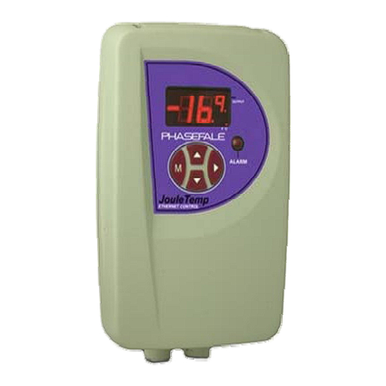
Display/Keyboard operation: Summary
Display shows temperature with 0.1°C or 0.1°F decimal precision
Display flashing temperature indicates a current or previous alarm
Large alarm LED flashes on/off during alarm or steady on during alarm acknowledge
Decimal point below small digit flashing indicates a network alarm
Lower right hand decimal point of small digit indicates control output (usually cooling) in ON
Alarm ack: Press > to acknowledge prior alarms and set temp display to steady
JouleAlarm Instruction
Page 1 of 14
Issue 1
Advertisement
Table of Contents

Summary of Contents for Phasefale JouleAlarm
-
Page 1: Table Of Contents
Connector Positions and Ethernet Cabling ..................... 14 Introduction Thank you from Phasefale and congratulations of your purchase of Joule Alarm, a lot of research has help us to develop a unique controller that is capable of alarm temperature, pressure and humidity in rooms and in other atmospheres as well as controlling them.. -
Page 2: Programming Joule Alarm
This will also occur if the > key is pressed during the programming operation. Remember to store each altered value using M otherwise the programmed setting will be lost JouleAlarm Instruction Page 2 of 14 Issue 1... - Page 3 JouleAlarm Instruction Page 3 of 14 Issue 1...
-
Page 4: Main Settings [Aa1 Keypad Menu]
Network IP number 192.168.160.100 Log Period Mins. HAH* Humidity High Alarm 0-99% HAL* Humidity Low Alarm 0-99% HAt* Humidty Alarm Delay Time mins 0-99 min Lod * Load memory –no, bus,ALL No/bus/ALL JouleAlarm Instruction Page 4 of 14 Issue 1... -
Page 5: Browser Interface - Joule Alarm Standard Web Pages
Email pwd Email account password 15 ch. Browser Interface - Joule Alarm Standard Web pages JouleAlarm has 3 programmable standard pages, each with the following functionality; Page address Main Use /index.html User access to Joule Alarm, optionally a graph can be displayed on this page. -
Page 6: Channel Options
Events: a table of event based items with date, time, event, temps status. Events include abnormal or exception events such as alarm, alarm restoral, programming changes, and are stored as they occur. JouleAlarm Instruction Page 6 of 14 Issue 1... -
Page 7: Graph
Function: Choose the type of alarm function channels 1-4 ( Not Used, Normally Open, Normally Closed, Temperature Monitor, Temperature Alarm) Channels 5-8 (Not Used, Normally Open, Normally Closed, Temperature Monitor, Temperature Alarm, Low Pressure, High Pressure, Low Pressure Monitor, High Pressure Monitor) JouleAlarm Instruction Page 7 of 14 Issue 1... -
Page 8: General Settings [ No Keypad Menus For These Parameters]
Humidity High alarm: set the maximum humidity level before an alarm Humidity Low alarm: set the lowest humidity before an alarm Humidity Alarm Delay: set the alarm delay Buzzer can be disabled JouleAlarm Instruction Page 8 of 14 Issue 1... -
Page 9: Maintenance Page
Installation Pressure Transducer Installation A pressure sensor converts pressure measurements into analog electrical signals. Working range 1- 6 V Low Pressure Range 0 – 100 psi High Pressure 0 - 500 psi JouleAlarm Instruction Page 9 of 14 Issue 1... -
Page 10: Humidity Sensor Installation
JouleAlarm). Cables in excess of 50 m need shielding. Electrical Installation A solid ground connection is required for JouleAlarm Refer also to the electrical wiring diagram for connection details. The Active supply to the unit should be fused with a maximum rating to suit total load. -
Page 11: Joulealarm Ethernet Connection Options
It is possible to display your Joule Alarm on the internet: consult your computer administrator as this is beyond the scope of the tech support provided by Phasefale. One method is as follows: if you have a fixed IP address at your premises ( e.g. a mail server on your local LAN such as mail.company.com.au and a router with ports forwarding capability, you can assign local IP numbers to a port address, e.g. -
Page 12: Enclosure Installation /Cabling Routing
Enclosure Installation /Cabling Routing JouleAlarm Instruction Page 12 of 14 Issue 1... -
Page 13: Wiring Schematic
Wiring Schematic JouleAlarm Instruction Page 13 of 14 Issue 1... -
Page 14: Connector Positions And Ethernet Cabling
Connector Positions and Ethernet Cabling Above: connecting your JouleAlarm to a laptop or PC via direct connection or via a switch/hub/router Left: Main board connector positions This document is available online at http://www.phasefale.com.au/TechSupport.htm go to document directory and select JouleAlarm directory.
Need help?
Do you have a question about the JouleAlarm and is the answer not in the manual?
Questions and answers