Table of Contents
Advertisement
Quick Links
Advertisement
Table of Contents

Related Manuals for PC Engines ALIX.2 Series


Summary of Contents for PC Engines ALIX.2 Series
- Page 1 PC Engines ALIX.2 / ALIX.3 series system boards...
- Page 2 ©2007 PC Engines GmbH. All rights reserved. PC Engines GmbH www.pcengines.ch tinyBIOS and PC Engines are trademarks of PC Engines GmbH. All other marks and brands are property of their respective owners. ALIX system board 1/15/2008...
-
Page 3: Table Of Contents
Table of contents Federal Communications Commission Statement CE Declaration of Conformity Compliance information Recycling / disposal Introduction / features OEM options ALIX.2 series ALIX.3 series Getting started… Setup options PXE boot Power over Ethernet Known issues Operating system compatibility FreeBSD FreeDOS, MS-DOS 5.0... -
Page 4: Federal Communications Commission Statement
A copy of the test report will be provided on request. CE Declaration of Conformity We, PC Engines GmbH, declare that ALIX.2 and ALIX.3 series boards, when installed in PC Engines metal enclosures. (case1c1 / case1c2 / box2c), are in conformance with:... -
Page 5: Compliance Information
Testing for CE mark must be done at the level of the complete product, possibly including the wireless cards. Please contact PC Engines for assistance and documentation. For satisfactory resistance to electrostatic discharge events (ESD), the ALIX board should be grounded (e.g. -
Page 6: Introduction / Features
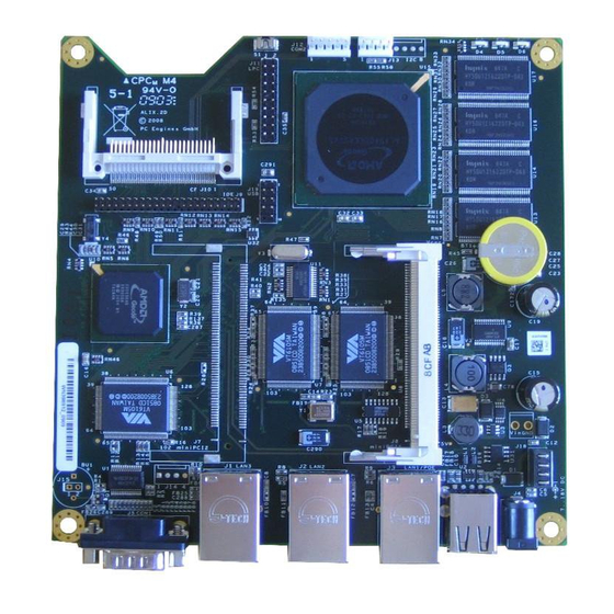
• 1 or 2 miniPCI sockets for 802.11 wireless cards and other expansion • 128 or 256 MB DDR SDRAM, 64 bit wide for high memory bandwidth • 512 KB flash for PC Engines tinyBIOS • CompactFlash + optional 44 pin IDE header for user’s operating system and application •... -
Page 7: Alix.2 Series
ALIX.2 series Configuration 2 LAN / 2 miniPCI, or 3 LAN / 1 miniPCI Power supply 7 to 20V DC, about 3 to 4W at Linux idle, peak about 6W without miniPCI cards and USB devices. Suggest a 18V / 15W supply. Center pin = positive, sleeve = ground, 2.1 mm diameter. -
Page 8: Alix.3 Series
ALIX.3 series Configuration 1 LAN / 2 miniPCI Power supply 7 to 20V DC, about 2.5 to 3.5W at Linux idle, peak about 5W without miniPCI cards and USB devices. Suggest a 18V / 15W supply. Center pin = positive, sleeve = ground, 2.1 mm diameter. Temperature range 0 to 50°C. -
Page 9: Getting Started
You should see tinyBIOS startup messages, memory size, CF disk geometry on the serial console. Setup options To enter setup, type S during the memory test. You should see something like the following: PC Engines ALIX.2 v0.98j 640 KB Base Memory 261120 KB Extended Memory... -
Page 10: Pxe Boot
PXE boot can be activated either through the E option in setup (always), or by pressing N during memory test (one time). PC Engines cannot provide technical support for the PXE module, too many possible failure points (Intel / Via PXE module, DHCP server, TFTP server, boot image etc). -
Page 11: Operating System Compatibility
Operating system compatibility Please keep in mind that ALIX.2 and ALIX.3 boards do not include a keyboard controller. Some boot loaders may hang and need to be modified. For best performance, include support for AMD Geode LX / CS5536, and use a current driver for the Via VT6105M LAN controller (supports TCP/IP checksumming, byte aligned transmit buffers). -
Page 12: Alix Block Diagram
ALIX block diagram Schematics will be made available to qualified customers. ALIX system board 1/15/2008... -
Page 13: Alix Connector Pinouts
ALIX connector pinouts References refer to ALIX.2 / ALIX.3. J5/J3 COM1 serial port The standard PC pinout is used. To connect to a PC, use a null modem or “Laplink” cable. Due to limitations of the AMD CS5536 companion chip, handshake signals are not available. data carrier detect (input) - not available on CS5536 RXD#... - Page 14 J6/J9 USB jack (build option) Dual USB 2.0 connections: switched +5V supply DATA4- negative data DATA4+ positive data ground switched +5V supply DATA3- negative data DATA3+ positive data ground J4/J2 DC power jack This is a generic DC jack connector with a 2.1mm center pin. Recommended input voltage is +18V. center VIN Positive input voltage sleeve GND...
- Page 15 HDACK# IDE DMA acknowledge ground HDIRQ IDE interrupt no connect HDA1 IDE address 1 HDPDIA# IDE diagnostic, 80 pin cable ID HDA0 IDE address 0 HDA2 IDE address 2 HDCS0# IDE chip select 0 HDCS1# IDE chip select 1 HDLED# IDE led output ground 5V power...
- Page 16 The LPC port is used in the factory to connect an alternate flash BIOS to start the board when the on-board flash is corrupted or blank. Use PC Engines adapter LPC.1A for this purpose if needed. The LCP port can also be used to connect a super I/O device. Unlike SC1100 based WRAP boards, this port cannot be reprogrammed as GPIO pins.
- Page 17 Specification: CR2032, horizontal mount, 20.4 mm lead spacing, for example: Renata CR2032FH1 Panasonic BR2032-1HE Buzzer (build option) Optional speaker. Driver circuit not populated, please contact PC Engines for instructions if you would like to add this. ALIX system board 1/15/2008...
-
Page 18: Status Leds
Status LEDs Status LEDs are all turned on by the BIOS on power up. The BIOS will turn off LEDs 2 and 3 before booting the operating system. Location GPIO read port write port LED1 (left) port 06100h bit 6 port 06100h bit 6 / 22 LED2 (middle) port 06180h bit 9... -
Page 19: Bios Post Codes
BIOS POST codes tinyBIOS writes POST / diagnostic codes to port 80h. To make these codes visible, use a miniPCI POST card such as PC Engines POST.5A. POST codes are: reset entry chipset initialization detect base memory size initialize shadow RAM...
Need help?
Do you have a question about the ALIX.2 Series and is the answer not in the manual?
Questions and answers