Table of Contents
Advertisement
Quick Links
Advertisement
Table of Contents

Related Manuals for Shini SG-14 Series

Summary of Contents for Shini SG-14 Series
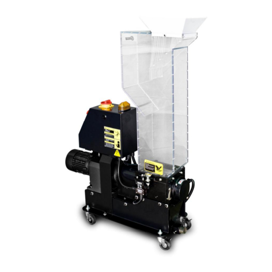
- Page 1 SG-14 Series Screenless Granulators Date: Dec, 2014 Version: Ver.B (English)
-
Page 3: Table Of Contents
Contents General Description .................. 9 1.1 Coding Principle ................. 10 1.2 Feature....................10 1.3 Technical Specifications..............12 1.3.1 Technical Specifications ............12 1.3.2 Dimensions................13 1.4 Safety Regulations ................14 1.4.1 Safety Signs and Labels ............14 1.4.2 Transportation and Storage of the Machine......16 1.4.3 Working Environment .............. - Page 4 2.3 Electrical Diagram ................30 2.3.1 Main Circuit (400V) ..............30 2.3.2 Control Circuit (400V) .............. 31 2.3.3 Components Layout (400V)............. 33 2.3.4 Electrical Components List (400V)........... 34 2.3.5 Main Electrical Circuit (230V) ..........35 2.3.6 Control Circuit (230V) .............. 36 2.3.7 Components Layout (230V).............
- Page 5 5.2 Stop Due to Other Reasons ............... 53 Maintenance and Repair ................. 55 6.1 Repair ....................55 6.1.1 Replace the Blades..............55 6.2 Maintenance ..................57 6.2.1 Daily Check ................57 6.2.2 Weekly Check................58 6.2.3 Monthly Check................. 58 6.2.4 Check and Maintenance of Gear Motor ........58 6.3 Cleaning.....................
- Page 6 Picture 1-1:Dimensions .................. 13 Picture 2-1:Working Principle ................. 18 Picture 2-2:Safety System................19 Picture 2-3:Emergency Stop Switch............... 20 Picture 2-4:Safety System................20 Picture 2-5:Assembly Drawing ............... 21 Picture 2-6:Cutting Chamber................24 Picture 2-7:Blade Rest ................... 25 Picture 2-8:Transmission Parts ..............26 Picture 2-9:Feed Box, Feed Port and Material Stopper........
- Page 7 Picture 4-2:Open the Storage Box ..............50 Picture 4-3:Main Power Switch ..............51 Picture 4-4:START, Emergency Button and STOP Button......51 Picture 4-5:Motor Reversed Protective Function..........52 Picture 6-1:Replace the Blades..............56 Picture 6-2:Star Screw ................... 58 Picture 6-3:Cleaning..................60 7(62)
- Page 8 8(62)
-
Page 9: General Description
Forbidden to process flammable or toxic material! SG-14 series granulators operate in super low speed to cut materials into well-proportioned granules. There are least dusts produced in the cutting process. Multiple security devices ensure high safety grade; automatic reverse running function ensures continuous operation. -
Page 10: Coding Principle
1) SG-14 series German-made gear motor features steady performance, long service life and high torque. 2) SG-14 series teeth cutters and cutting blades are integrally fitted in one cutting chamber. 3) New-type inclined teeth cutter reduces the possibility of stress concentration, enhance bearing capacity and converts force direction so that cutter lifespan can be prolonged. - Page 11 Chapter 6, which contains service instructions intended for service engineers. Other chapters contain instructions for the daily operator. Any modifications of the machine must be approved by SHINI in order to avoid personal injury and damage to machine. We shall not be liable for any damage caused by unauthorized change of the machine.
-
Page 12: Technical Specifications
1.3 Technical Specifications 1.3.1 Technical Specifications Table 1-1:Technical Specifications Model SG-1411 SG-1417 Motor Power (kW, 50/60Hz) 0.37 / 0.45 0.37 / 0.45 Rotating Speed (r.p.m, 50/60Hz) 26 / 32 26 / 32 Material of Teeth Cutters SKD-11 SKD-11 Number of Cutting Blades Number of Teeth Cutters Number of Large Teeth Cutlers Number of Small Teeth Cutlers... -
Page 13: Dimensions
1.3.2 Dimensions Picture 1-1:Dimensions 13(62) -
Page 14: Safety Regulations
Safety Regulations Follow the instructions in this manual to avoid personal injury and damage to machine components. The following safety measures shall be followed when operating the granulator. 1.4.1 Safety Signs and Labels Electrical installation must only be done by a competent electrician! Before the granulator is opened for servicing and maintenance, always disconnect the power with both the main switch and the control switch on the granulator. - Page 15 No need for regular inspection because all the electrical parts in the control unit are fixed tightly! When operate the granulator, please notice the following signs. Hazard High voltage! May lead to casualty or other serious danger. Please cut off the power before repairing. Circuit diagram should only be changed by professionals.
-
Page 16: Transportation And Storage Of The Machine
1.4.2 Transportation and Storage of the Machine Transportation 1) SG-14 series of granulators are packed in plywood cases with wooden pallet at the bottom, suitable for quick positioning by fork lift. 2) After unpacked, castors equipped on the machine can be used for ease of movement. -
Page 17: Rejected Parts Disposal
Shini (including employees and agents). Shini is exempted from liability for any costs, fees, claims and losses caused by reasons below: 1. Any careless or man-made installations, operation and maintenances upon machines without referring to the Manual prior to machine using. -
Page 18: Structural Features And Working Principle
2. Structural Features and Working Principle 2.1 General Description SG-14 series are belong to "by the press" granulator, which are designed for grinding different types of plastic waste. The granulator are controlled by main power switch, emergency stop button, start button, stop button and safety switches. -
Page 19: Safety System
In case the safety system of granulator is changed, our company will not perform our commitment. The replacement of all spare parts will be done by SHINI Company. Picture 2-2:Safety System 2.1.2.1 Emergency Stop Switch There is one red button on the control panel. -
Page 20: Picture 2-3:Emergency Stop Switch
Picture 2-3:Emergency Stop Switch 2.1.2.2 Safety System On the granulator is equipped the safety position switch for circuit breaker. In case the position of feed box is changed or the breaker is loosened, it will cut off the power supply. There are two safety switches on the granulator: one is located between the feed box and the cutting chamber while the other one is between the storage box and machine body. -
Page 21: Assembly Drawing
2.2 Assembly Drawing 2.2.1 Assembly Drawing Note: Please refer to 2.2.2 material list about the parts code. Picture 2-5:Assembly Drawing 21(62) -
Page 22: Parts List
2.2.2 Parts list Table 2-1:Parts List Part No. Name SG-1411 SG-1417 Gear motor YM10572100000 YM10572100000 Coupling cover Coupling YW11305500000 YW11305500000 Bearing cover on left side Left bearing block BW30001400010 BW30001400010 Left bearing sleeve BW30014000010 BW30014000010 Fixing plate for gear motor Movable castor YW03002500100 YW03002500100... - Page 23 Part No. Name SG-1411 SG-1417 Front case block at top BW30141100110 BW30141700110 Staggered blade * BW40141410010 BW40141410010 Fixed blade 2* BW40141630010 BW40141630010 Fixed blade 3* BW40314170010 Feed box base Flat gasket 10 YW66102500000 YW66102500000 Star knob YW09001000000 YW09001000000 Feed box BR90141100110 BR90141700010 Feed port...
-
Page 24: Cutting Chamber
2.2.3 Cutting Chamber Picture 2-6:Cutting Chamber 2.2.4 Cutting Chamber Parts List Table 2-2:Parts List Name Part No. Left bearing holder at top Layer Left bearing holder at bottom Front case block at bottom Right bearing holder at bottom Back case block at bottom Locating block Front case block at top Right bearing holder at top... -
Page 25: Blade Rest
2.2.5 Blade Rest Picture 2-7:Blade Rest 2.2.6 Blade Rest Parts List Table 2-3:Blade Rest Parts List Name Part No. Bearing Right bearing block Right bearing sleeve Teeth cutter Staggered blade Left bearing block Spring clip Left bearing block Main shaft 25(62) -
Page 26: Transmission Parts
2.2.7 Transmission Parts Picture 2-8:Transmission Parts 2.2.8 Transmission Parts List Table 2-4:Transmission Parts List Name Part No. Gear motor Coupling 26(62) -
Page 27: Feed Box, Feed Port And Material Stopper
2.2.9 Feed Box, Feed Port and Material Stopper Picture 2-9:Feed Box, Feed Port and Material Stopper 2.2.10 Feed Box, Feed Port and Material Stopper Parts List Table 2-5:Feed Box, Feed Port and Material Stopper Parts List Name Part No. Material stopper Feed box Feed port 27(62) -
Page 28: Storage Box
2.2.11 Storage Box Picture 2-10:Storage Box 2.2.12 Storage Box Parts List Table 2-6:Storage Box Parts List Name Part No. Storage box 28(62) -
Page 29: Main Body
2.2.13 Main Body Picture 2-11:Main Body 2.2.14 Main Body Parts List Table 2-7:Main Body Parts List Name Part No. Installation plate for control box Installation plate for gear motor Fixing plate for storage box 29(62) -
Page 30: Electrical Diagram
2.3 Electrical Diagram 2.3.1 Main Circuit (400V) Picture 2-12:Main Circuit (400V) 30(62) -
Page 31: Control Circuit (400V)
2.3.2 Control Circuit (400V) Picture 2-13:Control Circuit 1(400V) 31(62) -
Page 32: Picture 2-14:Control Circuit 2(400V)
Picture 2-14:Control Circuit 2(400V) 32(62) -
Page 33: Components Layout (400V)
2.3.3 Components Layout (400V) Picture 2-15:Components Layout (400V) 33(62) -
Page 34: Electrical Components List (400V)
2.3.4 Electrical Components List (400V) Table 2-8:Electrical Components List (SG-1411/1417) (400V) Symbol Name Specification Part NO. Main switch* 16A 690V 3P YE10200300000 Circuit breaker* 5A 400V 3P YE40603000000 Middle relay* 230V 50/60Hz YE03570700000 K2 K3 Contactor* 230V 50/60Hz YE00300100000 Auxiliary contact terminal Contactor* 230V 50/60Hz YE00301000000... -
Page 35: Main Electrical Circuit (230V)
2.3.5 Main Electrical Circuit (230V) Picture 2-16:Main Electrical Circuit (230V) 35(62) -
Page 36: Control Circuit (230V)
2.3.6 Control Circuit (230V) Picture 2-17:Control Circuit 1(230V) 36(62) -
Page 37: Picture 2-18:Control Circuit 2(230V)
Picture 2-18:Control Circuit 2(230V) 37(62) -
Page 38: Components Layout (230V)
2.3.7 Components Layout (230V) Picture 2-19:Components Layout (230V) 38(62) -
Page 39: Electrical Components List (230V)
2.3.8 Electrical Components List (230V) Table 2-9:Electrical Components List (SG-1411/1417) (230V) Symbol Name Specification Part No. Main switch* YE10200300000 Circuit breaker* Middle relay* 230V 50/60Hz YE03570700000 K2 K3 Contactor* 230V 50/60Hz YE00300100000 Auxiliary contact terminal Contactor* 230VAC 50/60Hz Safety relay 220VAC Overload relay* 1.6~2.5A... -
Page 40: Electrical Components Description
2.4 Electrical Components Description Picture 2-20:Electrical Components Description 1. Reversed PCB. 2. Transformer, provide suitable voltage for control circuit. 3. Fuse, perform the function of overload and short phase protection. 4. Circuit breaker, isolate or short circuit protection. 5. Electromagnetic switch, which can connect or disconnect the power from remote. -
Page 41: Installation And Debugging
3. Installation and Debugging Read through this chapter before installation. Must abide the following installation steps to avoid personnel injuries or damage of the machine! Take great care of handing the blades because they are very sharp and may cause cutting injuries! Power supply of the machine should be handled by qualified electricians! Be careful! Cutting blades must be put balanced, prevent it to rotate itself when do... -
Page 42: Installation Notice
3.1 Installation Notice: 1) Make sure voltage and frequency of the power source comply with those indicated on the manufacture's plate, which is attached to the machine. 2) Power cable and earth connections should conform with local regulations. 3) Use independent power cable and ON / OFF switch. The cable's dia. Should not smaller than those applied in the control box. -
Page 43: Installation Place
3.2 Installation Place Check and make sure the installation ground is level; there is enough intensity when it is running. Lockup the castors. Picture 3-2:Installation Place 3.3 Installation of Bearing and Blade Rest 1) Install the bearing 2. bearing washer 1. bearing sleeve 7 into the bearing base 3. -
Page 44: Installation Of Gear Motor And Coupling
Picture 3-4:Installation of Bearing and Blade Rest 2 4) Fix the bearing base on the cutting chamber. Picture 3-5:Installation of Bearing and Blade Rest 1 3 Notice! Daub the lubrication on the bearing and bearing base. Use proper twisting force to lock the screw tightly. 3.4 Installation of Gear Motor and Coupling 1) After complete the mounting of blade rest and cutting chamber to the base. -
Page 45: Installation Of Rotating Blade And Fixed Blade
Caution! To avoid cutters from self-rotating, use a thick wooden block to lock the cutters when install or uninstall the gear motor. Be careful! The cutting blade rest shall be put stably. Self turning of cutting tool shall be prevented prior to installation. At the time of operating, hand shall stay away from the cutting tool to avoid bodily injury. -
Page 46: Installation Of Feed Box, Feed Port And Storage Box
5) After installed the rotating blade rest to the housing, mount fixed blades that correspond with teeth cutters on pressing block and align their holes. Lockup the fixing screw (LOCTITE243 thread fixing glue is recommended). (Fixing screw for front fixed blade is M10x30, while for back fixed blade is M10x35). Picture 3-9:Installation of Rotating Blade and Fixed Blade 3 Caution! Because it is unable to adjust the space between rotating blade and fixed... -
Page 47: Picture 3-11:Installation Of Feed Box, Feed Port And Storage Box 2
Picture 3-11:Installation of Feed Box, Feed Port and Storage Box 2 3) Before fixing the feed port, place the plastic strips at the top of feed box and let feed port press against it. 4) Lay down the feed port and align its screw holes with the screw holes on the feed box, then lock the screws up (M8×20). -
Page 48: Operation Guide
Operation Guide Wear gloves during operating to avoid personal injury! Wear goggles during operating to avoid personal injury! 4.1 Startup Pretest Unpainted part of the machine has been covered with stainless oil. Before use, the stainless oil should be cleaned. 1) Clean with a towel. -
Page 49: Check The Running Direction Of The Motor
4.2.1 Check the Running Direction of the Motor 1) Open the door to check whether the feed box is closed. 2) Ensure the main power switch is in ON position. 3) Check the emergency stop. 4) Start the granulator via pressing the START button and stop the granulator via pressing the STOP button. -
Page 50: Shut The Feed Box And Storage Box
1) Shut off the power of granulator. 2) Remove the storage box. Picture 4-2:Open the Storage Box 4.4 Shut the Feed Box and Storage Box 4.4.1 Shut the Feed Box 1) Check to ensure there is no powder left in the interface or corners. 2) Close the feed box forwardly. -
Page 51: Picture 4-3:Main Power Switch
Picture 4-3:Main Power Switch START button and STOP button: These two buttons control the startup and stop of the machine. Emergency stop: When an accident happens, this button can do a favor. Picture 4-4:START, Emergency Button and STOP Button Caution! If there are ungrinded crew materials in the feed box or cutting chamber, the granulator shall NOT be stopped, otherwise the crew materials will blockade the rotor and the motor will be overloaded next time you start... -
Page 52: Motor Reversed Protective Function
4.6 Motor Reversed Protective Function When there are hard material appear in the feed box and cutting chamber or for other reason the cutting blades can not cut, this unit will enable blade shaft reverse rotating with alarm, It resumes normal operation automatically after 3 seconds later, so to keep granulating material. -
Page 53: Trouble-Shooting
Trouble-shooting 5.1 Granulator Can Not Work 1) Check if the emergency stop has not been reset. If not, rotate the Button anti-clockwise to reset it. 2) Check whether the door is closed. If not, the machine could not be started. 3) Check if the feed box is completely closed. - Page 54 Connection failure or looseness of safety switch or limit switch can also result in operation failure. Note! Do not disconnect to safety switch or control switch. 54(62)
-
Page 55: Maintenance And Repair
Maintenance and Repair 6.1 Repair All the repair must be done by professionals to avoid damage to machine and harm to human body. 6.1.1 Replace the Blades Caution! Warning: Self-rotation exists due to non-balanced forces or unstable bary center. Wear gloves to avoid being cut and be careful of the sharp blades! More details about replacing or maintaining the blades to see chapter 3.5. -
Page 56: Picture 6-1:Replace The Blades
Picture 6-1:Replace the Blades Caution! To decrease the possibility of harm to other people, the replacement action must be conducted by oneself. To avoid self- rotation, block the rotating blades with a thick wood block. Be careful with the sharp blades. Each time to replace the blade, the screw and insulation ring must be replaced also. -
Page 57: Maintenance
Clean carefully the fixed blades and rotating blades and then install them. Caution! Each time to replace the blade, the screw and insulation ring must be replaced also. Install the rotating blades, then the fixed blades, finally the front fixed blades. More details about replacing or maintaining the blades to see chapter 3.6. -
Page 58: Weekly Check
Picture 6-2:Star Screw 6.2.2 Weekly Check 1) Check the power wire to see whether there is any damage. If so, replace it immediately. 2) Check the safety switch. 6.2.3 Monthly Check Check the gear motor's working condition. 6.2.4 Check and Maintenance of Gear Motor Check lubricating oil for every six months or after 3000 hours in operation 1) Check oil level: 1. -
Page 59: Cleaning
cooled and there is no potential burning danger! 2) Lay an oil pan under the oil drainage plug. 3) Open the oil level plug、air valve and oil drainage plug. 4) Drain all the lubricating oil out. 5) Install oil drainage plug. 6) Fill in new lubricating oil in same brand. -
Page 60: Picture 6-3:Cleaning
Picture 6-3:Cleaning Do step 5 for every time of machine cleaning and also it at least has to be done for one time after 300 hours in operation. 60(62) -
Page 61: Maintenance Schedule
6.4 Maintenance Schedule 6.4.1 About the Machine Model Manufacture date Ф Voltage Frequency Power 6.4.2 Check After Installation Check if pipe connections are firmed locked by clips. Check the gap between fixed blade and rotating blade. Check the rotating balance of the belt wheel. Electrical Installation Voltage: Specs of the fuse: 1 Phase... -
Page 62: Check Half-Yearly Or Every 1000 Running Hours
Check the overload protection function of the motor. Check motor reversed running function. Check the tightness of the blades. 6.4.6 Check Half-yearly or Every 1000 Running Hours Check or replace lubrication for gear motor. Check lubrication of bearing. Check coupling. Evaluation of the machine condition.
Need help?
Do you have a question about the SG-14 Series and is the answer not in the manual?
Questions and answers