Table of Contents
Advertisement
Advertisement
Table of Contents

Summary of Contents for Tykma ELECTROX Minilase
-
Page 2: Table Of Contents
Minilase™ e System Guide Contents Getting Started............................3 Power up your Minilase™ ........................4 Installing the USB Drivers ........................7 Installing the USB Drivers and Software..................8 Installing the Minilase Pro SE Software..................10 Enabling the Laser and Operating the Touch Screen Interface .......... 14 Door, Focus and Operator Pendant Function ................ - Page 3 Microsoft Corporation. Citrix™ is a trademark of Citrix Systems Inc. They are only used in this document for editorial purposes. All information and content in this document is property of TYKMA™ Inc. and cannot be shown, distributed, modified and/or reproduced through electronic, mechanical or any other way, without written consent from TYKMA™...
-
Page 4: Getting Started
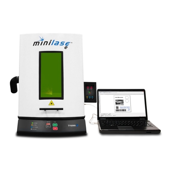
Minilase™ e System Guide Getting Started Thank you for purchasing the Minilase™ e laser marking system. Minilase™ e is shipped fully assembled and is completely operational within 15 minutes. Most laser marking systems require elaborate, time consuming setup, plus complex assembly and training sessions. -
Page 5: Power Up Your Minilase
Minilase™ e System Guide Power up your Minilase™ Step 1: Remove the Minilase™ system from the packing and place it on your desk or benchtop where you plan to use it. Your Minilase™ weighs approximately 130lbs and requires at least two individuals to move the system. - Page 6 Minilase™ e System Guide Step 3: Connect the supplied power cord to the input plug on the right side of the system; then plug the power cord into a power conditioner or power strip with surge protection. You can now power up your Minilase™...
- Page 7 Minilase™ e System Guide Step 5: If you have not already done so, please power up your desktop or laptop PC that you will use to run the Minilase™ Pro SE software. Step 6: Plug the supplied USB cable into the “USB to PC”...
-
Page 8: Installing The Usb Drivers
Minilase™ e System Guide Installing the USB Drivers Before installation of the USB drivers, please make sure you have followed steps 1-4. Before proceeding with the software installation, you must first install the drivers to support the USB connection from the PC to the laser. Step 1: Insert the provided USB drive into an open USB port on your computer. -
Page 9: Installing The Usb Drivers And Software
Minilase™ e System Guide Installing the USB Drivers and Software. Step 3: Choose “Browse my computer for driver software”. Step 4: Choose “Browse” and locate the USB drive provided with your system. Select the folder “Software” which contains the drivers. P a g e... - Page 10 Minilase™ e System Guide Step 5: Click “Next”. Step 6: The driver is successfully installed. You may now proceed to the software installation. P a g e...
-
Page 11: Installing The Minilase Pro Se Software
Minilase™ e System Guide Installing the Minilase Pro SE Software. Before installation of the software, please make sure you have followed steps 1-11. After the driver installation is complete, proceed with the install of the software. Step 1: Locate the folder titled “Software” on the included USB drive, then choose the folder titled “Minilase Pro SE”... - Page 12 Minilase™ e System Guide Step 2: The installer should automatically detect the configuration files located on the USB drive. If so, the message “Configuration File Found in Directory! Click Next!” will appear. You may now proceed by clicking next. If the message is not present, click “Load Configuration”...
- Page 13 Minilase™ e System Guide Step 3: Once the configuration file is loaded, selected or the machine configuration is determined you will see this screen. Click “Install”. 12 | P a g e...
- Page 14 Minilase™ e System Guide Step 4: Upon completion of the software installation, you may now launch the software. 13 | P a g e...
-
Page 15: Enabling The Laser And Operating The Touch Screen Interface
Minilase™ e System Guide Enabling the Laser and Operating the Touch Screen Interface Step 1: To enable the laser, you must utilize the touch screen on the side of the system and enter the correct password. Press the red power icon located in the center showing the status of “Laser Off”. - Page 16 Minilase™ e System Guide Step 3: The screen will now show the status of “Laser On” and the power icon will turn green. Step 4: If you wish to disable the laser system, press and hold the green power icon for 2 seconds or until the blue circular status icon is a complete circle.
- Page 17 Minilase™ e System Guide Step 5: The touch screen also provides access to a few lower level menus. On these menus you can view system status or contact information for our service and support group. Step 6: By pressing the “Help” button you will see contact information for our service and support group.
- Page 18 Minilase™ e System Guide Step 7: While marking, the touch screen will show the following status. To stop the marking, you can press anywhere on the screen. 17 | P a g e...
-
Page 19: Door, Focus And Operator Pendant Function
Minilase™ e System Guide Door, Focus and Operator Pendant Function Door Operation: To open the door, grab the front mounted handle and pull up with lite pressure. The door will slide upward to the open position. The door is assisted and therefore requires very little energy to open. - Page 20 Minilase™ e System Guide Labjack for Focal Height Adjustment: Minilase™ e features a high precision labjack system for focal height adjustment. Adjusting Focus: Your Minilase™ system is equipped with an easy focus finder system comprised of two red aiming beams emitted from the marking head.
- Page 21 Minilase™ e System Guide Adjusting Height for Focus: To focus on your part, use the large front adjustment wheel as shown in the image. Move the labjack height up or down by turning the large adjustment wheel clockwise or counter clockwise. As the part height increases, lower the labjack height.
- Page 22 Minilase™ e System Guide Status LEDs: The front operator pendant on the Minilase™ machine includes system status LEDs. When the system is enabled, you will note that the “Laser Ready” light is enabled as shown in the phot on the right. Laser Busy will show orange when the system is marking.
-
Page 23: Programming And Marking
Minilase™ e System Guide Programming and Marking To begin creating marking programs, please consult the Minilase™ Pro SE software manual located in the “Manuals” folder located on the included USB drive. You can quickly run through a basic guide to creating a marking program to verify system functionality on Page 98 of the software manual. -
Page 24: Maintenance - Cooling Fans
The filter included should be monitored and replaced when enough debris is present to restrict air flow. Replacement filters can be ordered through TYKMA Electrox using part number: 19155K8. To remove the filter material, simply grab the black plastic cover on the top and bottom and pull gently at an angle. -
Page 25: Service Ports
Minilase™ e System Guide Service Ports On the operator left rear side of the unit are two service ports. One service port also has the ability to support I/O but does not ship preconfigured for this capability. The service ports can be used by laser technicians to troubleshoot and/or update firmware on the system. -
Page 26: Technical Specifications
Minilase™ e System Guide Technical Specifications 17″W x 34″L x 24″H / 130lbs System Dimensions (mm) 432W x 864L x 610H / 60kg 160S (100mm x 100mm) Standard Marking Field (3.93″ x 3.93″) 13.5″W x 9.5″L x 4.625″H (mm) Standard Max Part Size (160 Lens) 342W x 241L x 117H 254S (140mm x 140mm, 5.5″... - Page 27 Minilase™ e System Guide Available Ports Diagnostic Cooling Air Cooled 36 Month Comprehensive Warranty Unlimited Hours 26 | P a g e...
-
Page 28: Basic Troubleshooting
Minilase™ e System Guide Basic Troubleshooting Issue Resolution Ensure the laser system is Upon launching software, a message appears stating “No laser system or powered on. Check to make sure the USB dongle is present. The software will function in a limited demo mode.”... -
Page 29: Contact Information
Minilase™ e System Guide Contact Information The service and support line at our US headquarters is available 24/7, 365 at +1 (740) 779-9918 or email us at service@permanentmarking.com. If you purchased your system from your local distributor, you may also contact them for support.
Need help?
Do you have a question about the ELECTROX Minilase and is the answer not in the manual?
Questions and answers