Table of Contents
Advertisement
Quick Links
REDI CONTROLS, INC.
Installation, Operation & Maintenance Manual
Literature File No. 1117-02
Redi-Purge
™
Model PRG-113-C3 & C4
Microprocessor Controlled
Ultra High Efficiency
Purge Unit
for
Low Pressure Chillers
Manufactured in accordance with
ETL Listed
ASHRAE Guidelines 3-1990 Sec. 4.7 and
Standard 15-1992 Sec. 8.3, 8.7 and 10.4
3104248
Advertisement
Table of Contents
Troubleshooting

Subscribe to Our Youtube Channel
Summary of Contents for Redi Controls Redi-Purge PRG-113-C3
- Page 1 REDI CONTROLS, INC. Installation, Operation & Maintenance Manual Literature File No. 1117-02 Redi-Purge ™ Model PRG-113-C3 & C4 Microprocessor Controlled Ultra High Efficiency Purge Unit Low Pressure Chillers Manufactured in accordance with ETL Listed ASHRAE Guidelines 3-1990 Sec. 4.7 and Standard 15-1992 Sec.
- Page 2 Revised Technically as of October 11, 2013 © 1994 REDI CONTROLS, INC., GREENWOOD, INDIANA...
-
Page 3: General Information
GENERAL INFORMATION YOU ARE URGED TO READ THIS MANUAL COMPLETELY BEFORE INSTALLING AND/OR OPERATING THIS UNIT Upon Receiving Your Unit Inspect the unit for possible damage caused during shi pping. Contact Equipment Servicing before attempting to use a damaged unit. Warnings and Cautions Warnings Cautions... -
Page 5: Table Of Contents
T a b l e of C o n t e n t s GENERAL INFORMATION ......................3 Upon Receiving Your Unit............................3 Warnings and Cautions............................... 3 INSTALLATION .........................9 Before You Start................................9 Purge Specifications.............................. - Page 6 2. Chiller mounted condenser temperature sensor TS3 (option) ................21 3. Chiller evaporator pressure Pre-Alarm PS1 (option) ..................... 21 System Components ..............................21 Purge Control Panel ..............................21 Microprocessor Circuit Board........................... 22 Compressor unit (C1) ............................... 22 Pumpout Compressor (C2)............................22 Temperature Sensor (TS1)............................
- Page 7 “BYPASS” Keypad Switch ............................33 Exiting Fault “BYPASS” Mode..........................34 “DIAG.” Keypad Switch ............................34 “LOGs” Keypad Switch ............................36 Log 1 - 30 day "sliding window" average purge pumpout time (chiller OFF) ............36 Log 2 - 30 day "sliding window" average purge pumpout time (chiller on) ............36 Log 3 - Pumpout time that has occurred during last 24 hour “sliding window”...
- Page 8 Purge Tank Service ..............................49 Water Removal................................. 49 Purge Tank at a Positive Pressure......................... 49 Purge Tank at a Negative Pressure ........................50 Figure 8. - Electrical Schematic (for York Chillers see Figure 8A)................ 51 Figure 8A.
-
Page 9: Installation
INSTALLATION Before You Start Caution: Federal Refrigerant Recycling Regulations require that the chiller, during servicing, be either completely evacuated or pressurized to atmospheric pressure (0 psig) prior to opening the refrigerant circuit to the atmosphere. Failure to comply, or using means other than heat to elevate refrigerant pressure, violates Section 608 of the Clean Air act. -
Page 10: Purge Specifications
Purge Specifications Electrical Power Requirements: 103-127 VAC, 50/60 Hz., 1-Phase, 15 Amp Fused Circuit Remote Alarm Relay ( RY7) Contact Rating: (Form C) 120 VAC; 15 Amp Operating Environment: 40°F to 120°F, 5% to 95% relative humidity Storage Environment: -20°F to 120°F Dimensions (approximate): 19"... -
Page 11: Removing Old Purge Unit
Removing Old Purge Unit Replacing the existing purge system on older centrifugal chi llers with the new Purge Unit requires that the existing purge system be completely disconnected and removed. Before proceeding with the retrofit it is important that the installer thoroughly review and understand the following instructions for preparing the chiller to remove the old purge system. -
Page 12: Installing The Unit
Installing the Unit Installation of the new purge unit requires several wiring and hardware modifications. To insure proper installation, it is important that the installer thoroughly read an d understand the following instructions. NOTE: The installer should record all changes and modifications made to the chiller during installation and provide a copy for inclusion with the maintenance records of the chiller. -
Page 13: Refrigerant Line Connections
Refrigerant Line Connections The purge requires three separate refrigerant line connections (see Figure 1 on page 12): A 1/2" purge inlet line between the purge tank and the condenser purge outlet. The same condenser outlet the old purge used. A 1/4" liquid return line from the purge tank dra in solenoid valve to the liquid return angle valve on the evaporator. -
Page 14: Liquid Refrigerant Return Line
Liquid Refrigerant Return Line The liquid refrigerant return line runs between the evaporator's original liquid return angle valve and drain back solenoid valve L3 (see Figure 1 on page 12) or the outlet of the optional liquid line filter-drier, if used. Use 1/4" refrigerant-grade copper tubing. Purge Line Condensor NOTE: The Liquid Refrigerant Return Line MUST connect... -
Page 15: Pumpout Compressor Discharge Vent Line
NOTE: The entire length of the vapor line, including the in-line filter-drier set, must slope toward either the purge inlet or the chiller condenser. Avoid sagging of the tubing where pockets of liquid refrigerant can condense and accumulate. Pumpout Compressor Discharge Vent Line When venting the pumpout compressor to the emission collection canister, or to the outdoor atmosphere, or the chiller rupture disc vent line, it is important to use 3/8 -inch line size to minimize pressure drop. - Page 16 Preliminary Checkout and Power-Up (continued) Check the Unit fuse (F1) to insure that it is properly installed (see Figure 4 on page 17). Check to make sure that all internal connections are secure. Apply power to purge unit and measure voltages at TB1 -1 & TB1-6 and TB1-3 & TB1-6 (see figures 8 and 8A on pages 51 and 52).
-
Page 17: System Components
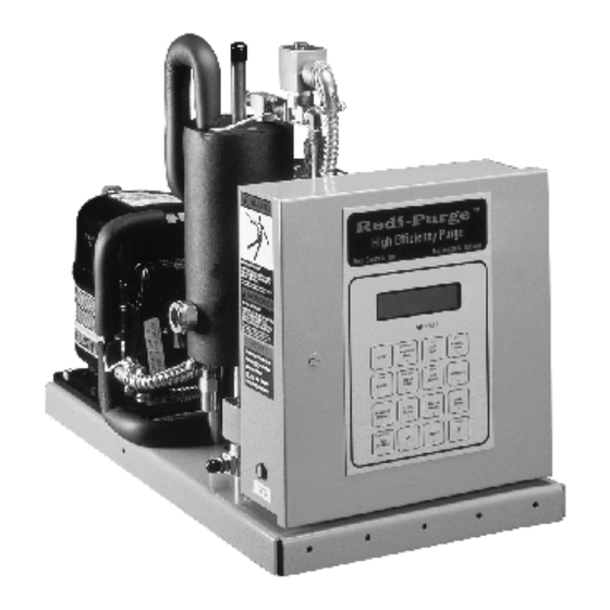
SYSTEM COMPONENTS Figure 2. - Major Components Sight Electrical Glass Control Air Cooled Condensing Unit Pump-out Compressor (Behind Purge Tank) Purge operation is controlled via the 16 keypad switches and display located on the front of the unit control box (see figure 3 and 4 below). Figure 3. -
Page 18: Figure 5. - Flow Schematic And Component Location
Figure 5. - Flow Schematic and component location High Efficiency Purge with optional Emission Collection Canister (Together, system expels .0049 lbs CFC's or less per lb of air removed) -
Page 19: Operational Overview
OPERATIONAL OVERVIEW Air-Cooled Condensing Unit The air-cooled condenser on the purge unit provides the necessary cooling source to condense and separate refrigerant from non -condensables in the purge tank. The unit operates most efficiently within an ambient temperature range of 40° to 120°F. The rate at which the purge removes air from the chiller is proportionate to the ambient temperature. -
Page 20: Purge Tank
Purge Tank The purge tank consists of a refrigerated cooling coil, liquid level switch, liquid level sight glass, water bleed-off valve, and a non-condensables exhaust port. The non-condensables are removed from the purge tank via pumpout solenoid valve L4 and the pumpout compressor. -
Page 21: Optional Accessories
Optional Accessories The purge unit can be equipped with three optional accessories. 1. Emission Collection Canister saturation alarm (option) If the electronic refrigerant emission monitor for the ZERO EMISSION CANISTER accessory is desired to be incorporated into the purge units control it will indicate when the emission collection canister becomes saturated with refrigerant. -
Page 22: Microprocessor Circuit Board
Microprocessor Circuit Board The microprocessor circuit board contains the central processing unit that monitors the various sensor inputs and controls the appropriate outputs such as the relays to activate the various purge functions. (see Figure 4 on page 17) Compressor unit (C1) Air cooled condensing unit compressor. -
Page 23: Remote "Purge Fault" Alarm Relay (Ry7)
Remote “Purge Fault” Alarm Relay (RY7) Remote purge fault alarm relay RY7 is used to enunciate a purge fault alarm at a location remote from the purge unit. (see Figure 4 on page 17). Auxiliary Relay (RY8) Auxiliary relay RY8 is used when Pre-Alarm option is installed for interlocking peripheral equipment. -
Page 24: Quick Start 6 - Operation
6 QUICK START 6 - OPERATION NOTE: If your chiller has been down for repair or has a lot of air in it you may wish to read the service tips starting on page 58 before commencing purge operation. Quick Start Introduction This procedure can only be used if you have properly installed the purge unit and have completed the PRELIMINARY CHECK OUT AND POWER UP starting on page 15. -
Page 25: Select Desired Operating Mode
Select Desired Operating Mode The purge unit has three (3) operational modes. Select desired mode by pressing one of the following keypad switches (MANUAL, AUTO, or ADAPTIVE). In the "MANUAL" mode, purge operation is continuous, whether chiller is on or off. The "MANUAL" mode is recommended only for service procedures. -
Page 26: Setting Operational Parameters
Setting Operational Parameters To change the purge unit’s operational parameters, temporarily switch Dip switch S1-position 4 to the “ON” position (this disables the Security Lock feature -- see Figure 4 on page 17 for Dip switch S1 location). Once operational parameters are set, switch S1-position 4 back to the “OFF”... -
Page 27: Drain Cycle Setting (Sets Ls1 Liquid Level Switch Make/Break Hysterisis)
Use the cursor movement keypad switches “<“ and “>“ to move the cursor beneath the position you want to change. Use the numbered keypad switches to enter the desired val ue, then press the ENTER key. To change another operational parameter SCROLL to the appropriate display. -
Page 28: Dip Switch S1 Settings
Dip Switch S1 Settings (Dip Switch S1 only needs to be set if any of the optional sensors have been installed, or when setting operational parameters (see Figure 4 page 17 for Dip switch location). NOTE: All dip switches must be set to the “off” “ position unless one or more of the fol lowing options are installed. -
Page 29: Safety Features
Safety Features The Microprocessor Control provides a full array of safety features that will terminate purge operation when an abnormal condition develops in any one of the following areas: Maximum Allowable Pumpout Time Exceeded (PURGE FAULT) Purge operation is terminated and a latching " Purge Fault" diagnostic occurs when the pre-set maximum allowable purge pumpout time is exceeded during any 24 -hour “sliding window”... -
Page 30: Lcd Display
DISPLAY FAULT EXIT Compressor Pump Drain MANUAL ADAPTIVE AUTO Mode Mode Mode STOP AUX Valve Alarm Scroll CLEAR SETTINGS ENTER LOGs CLOCK LOGs SENSORS STATUS DIAG. Display Display Mode Display Toggle On/Off Function Figure 7. - RESET Fault > < BYPASS Purge Control Panel... -
Page 31: Set Clock" Keypad Switch
“SET CLOCK” Keypad Switch Setting the clock - “SET CLOCK” To set the clock, press the keypad switch. Set CLK 00:00 AM or PM Display changes to: use < >, 0 - 9 The display reads 00:00 which stands for Hours:Minutes. The underline is the cursor, to set the clock, use the cursor movement (“<“... -
Page 32: Auto" Keypad Switch
“AUTO” Keypad Switch To enter the "Auto" mode press the "Auto" Switch. The display will read “On Auto” mode indicating the purge is operating in the "Auto" mode. The purge will remain in the “Auto" mode until another keypad switch is pressed, such as STOP, or SET CLOCK or when a different mode is selected. -
Page 33: Sensors" Keypad Switch
“SENSORS” Keypad Switch NOTE: Can be used in conjunction with the DIAG. Switch for system diagnosis. Used to view the following sensory data: 1) Purge condensing unit compressor suction temperature (Superheat). Superheat °F Displayed: 2) Purge tank evaporating temperature. Evaporator °F Displayed: Normal Range -5º... -
Page 34: Exiting Fault "Bypass" Mode
Time left: 00:00 Exiting Fault “BYPASS” Mode The Fault “BYPASS” mode can be exited at any time by again pressing the Fault “BYPASS” Switch. The recommended "FAULT Bypass time" setting is 4 hours. NOTE: When in this mode the display will alternate between the “Fault Bypassed” display and the current operating mode. - Page 35 Examples: “Pump” keypad switch (press to activate, press again to deactivate) Used to activate pumpout circuit which includes: pumpout compressor C2 pumpout solenoid valves L1 and L2 Pumpout Relay RY2, with its associated LED indicator Diagnostics Mode Displayed: OUTPUTS = P “Drain”...
-
Page 36: Logs" Keypad Switch
Diagnostics Mode Displayed: OUTPUTS = B NOTE: Purge will remain in the Diagnostic mode until the STOP keypad switch is pressed. NOTE: Note: The “SENSORS” keypad switch can be used while in the diagnostic mode. “LOGs” Keypad Switch Log 1 - 30 day "sliding window"... -
Page 37: Log 3 - Pumpout Time That Has Occurred During Last 24 Hour "Sliding Window" Period
To advance to next Log press “SCROLL” To exit “LOGs” display press “STATUS” Log 3 - Pumpout time that has occurred during last 24 hour “sliding window” period Last 24 Hours Displayed: Pump out : 00:00 (hours:minutes) To advance to next Log press “SCROLL” To exit “LOGs”... -
Page 38: Log 7 - Total Accumulated Purge "Pumpout" Time Since Installed
Log 7 - Total accumulated purge “pumpout” time since installed Cumulative H:M Displayed: PumpOut 00000:00 (hours:minutes) To advance to next Log press “SCROLL” To exit “LOGs” display press “STATUS” Log 8 - Average daily pumpout time for last 30 day period 30 Day Pump Out Displayed: Avg Mins. -
Page 39: Log 11 - Interval Log - Total Chiller Run Time Since Log Last Reset
To advance to next Log press “SCROLL” To exit “LOGs” display press “STATUS” Log 11 - Interval Log - Total chiller run time since log last reset. This log is provided to help the operator track desired service intervals, such as chiller run time since last oil change, or run time hours until next refrigerant analysis, etc.. -
Page 40: Reset" Keypad Switch
“RESET” Keypad Switch RESET is used to re-initiate purge operation following a purge fault condition (see FAULT INDICATION page 46). RESET is also used to reset the Interval log. “STATUS” Keypad Switch Allows operator to display the current purge unit operating mode. The “ STATUS” keypad switch can also be used as the exit key for LOGs, CLEAR LOGs, and SENSORS display. -
Page 41: Logs Display
When the Purge is in one of the three operational modes the current STATUS display will indicate current operational status by displaying one of the following (with the appropriate time information see example below). On Manual Displayed: On Auto On Adaptive Off Auto Off Adaptive On Adaptive... -
Page 42: Log 4 - Pumpout Time First 3 Hours After Last Chiller Shutdown (Hrs & Min.)
Log 4 - Pumpout time first 3 hours after last chiller shutdown (Hrs & Min.) Indicates pumpout activity during the first three hour period after the last chiller shutdown. Sometimes not all of the air that has leaked into the ch iller can be completely purged while the chiller is operating. -
Page 43: Log 10 - Number Of Adaptive Only Run Cycles "Chiller Off" (Maximum 8 Cycles Per Day)
NOTE: In the ADAPTIVE or AUTO mode the number of ON/OFF cycles per day are based upon historical data from a 30 day average (sliding window) of purge operation. Log 10 - “Chiller OFF” Number of Adaptive only run cycles maximum 8 cycles per day) Indicates the number of current minimum “ON”... -
Page 44: Miscellaneous" - Informational Displays
“MISCELLANEOUS” - Informational Displays Pump-out Display When the purge unit is exhausting non-condensables the display will alternate between the current operating mode and the pumpout display. Pump out Active Displayed: Duration: 00:00 Example: (minutes & seconds) DRAIN BACK EQUALIZATION CYCLE Under certain conditions (such as when the purge is operating while the chiller is OFF), pressure gradient imbalances may developed which can retard liqu id drainage from the purge tank. -
Page 45: Sensor Error Displays
If however, “Liq. Level HIGH” remains displayed continuously for two (2) minutes the purge will automatically enter a “Drain Back Equalization Cycle” which can last up to 10 minutes. Drain Equalizing Displayed: Max. Delay : 00:00 (min. & sec. to “Drain Fault”) If the liquid level switch LS1 senses proper drainage (LS1 contact reopens) anytime during the 10 minute Drain Back Equalization Cycle the purge unit will automatically resume normal operation. -
Page 46: Fault Indications
Fault Indications PURGE FAULT Indicates maximum allowed pumpout time during any 24 sliding window hour period has been exceeded PURGE FAULT Displayed: When purge pumpout time exceeds pre-set maximum allowed pumpout time, (see SETTINGS operating parameters starting on page 26) the purge will Lock -Out on “PURGE FAULT”. DRAIN FAULT Indicates the purge is "OFF"... -
Page 47: Maintenance
MAINTENANCE This section discusses the Purge system maintenance requirements and procedures, and presents basic purge troubleshooting procedures. Periodic Maintenance The following maintenance procedures are required to assure efficient and reliable operation of the Purge. WARNING Certain servicing procedures expose you to refrigerant. To minimize the possibility of injury, follow the safety procedures on the label and in the material safety data sheet for the refrigerant. -
Page 48: Table 1 - Determining Refrigerant Moisture Content
After replacing filter-drier, you can not rely on a moisture indicator reading to evaluate refrigerant moisture content until the chiller is operating and th e purge unit has logged at least 72 hours of “Total Purge Condensing Unit Run Time”. Reading from Moisture Indicator Ambient Normal... -
Page 49: Filter-Drier Replacement
Filter-Drier Replacement Optional liquid return line filter-drier: ( if used 1. Turn off the purge by pressing the purge control “STOP” switch. 2. Isolate the purge from the chiller by closing both the vapor isolation ball valve and the liquid return angle valve. -
Page 50: Purge Tank At A Negative Pressure
Purge Tank at a Negative Pressure If the purge tank is at a negative pressure, as indicated by the chiller condenser pressure gauge, it will be necessary to slightly pressurize the purge tank. First, isolate the purge tank by closing the vapor inlet isolation ball valve (V1 in Figure 5 on page 18) and the liquid return angle valve at the chiller evaporator. - Page 51 + 5 VDC Optional Battery DCV Ground Microprocessor Board Model PRG-113-C3 12 VAC 12 VAC +6 VDC +12 VDC ACI-1H ACI-2H Purge "FAULT" Relay ACI-1L ACI-2L RLY-1 RLY-2 RLY-3 RLY-4 RLY-5 RLY-6 RLY-7 RLY-8 1 Amp / 250 V LINE L1 N.O.
-
Page 52: Figure 8A. - Wiring For York "Optiview" And "Micro Panel" Controls
+ 5 VDC Battery Optional DCV Ground Microprocessor Board Model PRG-113-C3 12 VAC 12 VAC +6 VDC ACI-1H +12 VDC Purge "FAULT" Relay ACI-2H ACI-1L ACI-2L RLY-4 RLY-8 RLY-1 RLY-2 RLY-3 RLY-5 RLY-6 RLY-7 1 Amp / 250 V LINE L1 N.O. -
Page 53: Trouble Shooting
Trouble Shooting Should an operational difficulty or malfunction occur, the diagnostic chart and checkout procedures on the following pages should help you to quickly determine the cause and corrective action. The Troubleshooting Chart has a "Symptom" column which describes what the unit is doing; a "Cause" column which identifies possible sources of the problem;... -
Page 54: Troubleshooting Chart (Continued)
Troubleshooting Chart (continued) Symptom Cause Solution The Purge Display reads: Drain Solenoid Valve (L3) is defective Repair or replace the valve. Purge tank level switch (LS1) is Replace the level switch. Drain Fault defective. Valve in drain-back line is closed Open the valve. -
Page 55: Purge Refrigeration System Diagnostic Procedure
Purge Refrigeration System Diagnostic Procedure Caution: Do not attempt to measure system discharge or liquid line pressure, it could result in the loss of your refrigerant charge. Operation of the purge unit's refrigeration system can be diagnosed by taking temperature measurements at various points in the refrigeration circuit (refer to Figure 6 on page 19.). -
Page 56: Temperature Sensor Ts2
Compressor Suction Temperature (Superheat) being displayed will begin to indicate a lowering of temperature as sensed by Temperature Sensor TS1. NOTE: The temperature meter and Temperature Sensor TS1 will not respond to changing temperature at the same rate. Temperature Sensor TS1 will probably lag somewhat behind the meter. -
Page 57: Checking For Calibration
Checking for Calibration Temperature Sensors TS1, TS2 and optional TS3 can be checked for proper calibration by measuring sensor resistance (see Table below). Temperature Resistance Table 2. - (° F) (° C) (Ohms) Sensor Temperature -12.2 14.07K -6.6 10.41K -vs- Resistance -1.1 7.782K 5.874K... -
Page 58: Service Tips
SERVICE TIPS Purging after Internal Chiller Repairs or Servicing The following procedures MUST be performed anytime after the chiller has been opened for repair and exposed to the atmosphere. Whenever air enters the chiller during servicing or repair it will have to be purged before restarting the chiller. THE PURGE WILL ACCOMPLISH THIS IN TWO PHASES, INITIALLY THE PUMPOUT COMPRESSOR WILL RUN CONTINUOUSLY DUE TO AN EXCESSIVE QUANTITY OF NON-CONDENSABLE AND A SMALL AMOUNT OF REFRIGERANT ENTERING THE PURGE TANK. -
Page 59: Bypassing Pumpout Flow Restrictor
Bypassing Pumpout Flow Restrictor THE PUMPOUT FLOW RESTRICTOR MAY BE TEMPORARILY BYPASSED TO ACCELERATE THE REMOVAL OF NON-CONDENSABLE WHEN LARGE AMOUNTS OF NON-CONDENSABLE ARE PRESENT. (TYPICALLY AFTER CHILLER REPAIRS.) NOTE: This is a manual procedure that will reduce the efficiency of the purge and should be used only during certain service conditions. -
Page 60: Locating A Leak
Locating a leak Because the purge has the ability to track and record purge activity while the chiller is both operating and off, it is possible to use this information to narrow the location of a leak to a particular area of the machine. Example: If the majority of pumpout activity occurs while the chiller is off (as indicated by the "Purge 30-day average pumpout time while chiller OFF"... -
Page 61: Data Logging (See Graph/Log Charts For Copying On Pages 62-66)
Data Logging (see Graph/Log Charts for copying on pages 62-66) The chiller operator may wish to maintain a log on a daily basis, recording at least the following data: Purge pumpout time last 24 hours. 30-Day Average pumpout time per day. Purge 30-day average pumpout time while chiller running. -
Page 62: Graph & Log - Purge Pumpout Time Last 24 Hours
Chiller No. ____Record for: __________: ______ (M o n t h) (Y e a r) 3 Graph & Log - Purge Pumpout Time Last 24 Hours 4 5 M in 4 0 M in 3 5 M in 3 0 M in 2 5 M in 2 0 M in 1 5 M in... -
Page 63: Graph & Log - 30-Day Average Purge Pumpout Time Per Day
Chiller No. ____Record for: __________: _____ (M o n t h) (Y e a r) 3 Graph & Log - 30-Day Average Purge Pumpout Time Per Day 4 5 M in 4 0 M in 3 5 M in 3 0 M in 2 5 M in 2 0 M in 1 5 M in... -
Page 64: Graph & Log - 30-Day Average Purge Pumpout Time - Chiller Running
Chiller No. ____Record for: __________:______ (M o n t h) (Y e a r) 3 Graph & Log - 30-Day Average Purge Pumpout Time - Chiller running 4 5 M in 4 0 M in 3 5 M in 3 0 M in 2 5 M in 2 0 M in 1 5 M in... -
Page 65: Graph & Log - 30-Day Average Purge Pumpout Time- Chiller Off
Chiller No. ____Record for: __________ :______ (M o n t h) (Y e a r) 3 Graph & Log - 30-Day Average Purge Pumpout Time- Chiller Off 4 5 M in 4 0 M in 3 5 M in 3 0 M in 2 5 M in 2 0 M in 1 5 M in... -
Page 66: Graph & Log - First 3 Hours Purge Pumpout Time After Chiller Shutdown
Chiller No. ____Record for: __________ :______ (M o n t h) (Y e a r) 3 Graph & Log - First 3 Hours Purge Pumpout Time after Chiller Shutdown 4 5 M in 4 0 M in 3 5 M in 3 0 M in 2 5 M in 2 0 M in... -
Page 68: Equipment Warranty
Within one year from the date of purchase, REDI CONTROLS will, repair any REDI CONTROLS’ product being used by the original purchaser, which is defective due to faulty materials or workmanship. REDI CONTROLS has the right to repair or replace a defective part or replace the entire product.
Need help?
Do you have a question about the Redi-Purge PRG-113-C3 and is the answer not in the manual?
Questions and answers