TBS CROSSFIRE Micro TX Manual

TBS CROSSFIRE Micro TX Manual

Adaptive long range remote control system

Advertisement

 
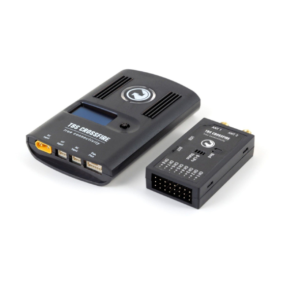
TBS CROSSFIRE R/C System
Adaptive Long Range Remote Control System
The TBS CROSSFIRE (XF) system is a R/C link system made for FPV enthusiasts. It features unheard of range 
without sacrificing basic functionality such as being immune to interference from onboard equipment, low 
latency control or two-way communications including telemetry functionality. 
Key features 
Long range, adaptive and robust remote control system for your aircraft 
Immune to on-board noise 
Two-way communication link with real-time link vitals and telemetry 
Self-healing frequency hopping link 
Receiver beacon mode to recover your downed aircraft  
Super easy binding and configuration via built-in OLED display, OpenTX LUA or TBS TANGO remote 
Low latency control for perfect immersive feeling 
Free output mappable 8 output diversity with integrated backup battery or super tiny receiver ( 4g 
weight only ) both with up to 12 channel PPM 
Ability to fly with multiple friends at the same time (10 or more) 
Dynamic self-selecting or selectable RF power from 10mW to 2W (local restrictions apply) 
Dedicated head-tracking input option for full FPV immersion 
Transmitter LED shows link health, OLED display for built in configuration  
Expansion port for future feature support 


Revision 2019-03-24
 

Advertisement

Table of Contents
loading
Need help?

Need help?

Do you have a question about the Micro TX and is the answer not in the manual?

Questions and answers

Subscribe to Our Youtube Channel

Summary of Contents for TBS CROSSFIRE Micro TX

  • Page 1: Key Features

        The TBS CROSSFIRE (XF) system is a R/C link system made for FPV enthusiasts. It features unheard of range  without sacrificing basic functionality such as being immune to interference from onboard equipment, low  latency control or two-way communications including telemetry functionality. ...
  • Page 2: Table Of Contents

        Table of content  Attention  Drone Racing Environment  Crossfire LED Color Coding  Overview  Setup  Connecting CROSSFIRE Standard Transmitter to radio  Using JR-adapter  Using Hitec/Graupner/JR-cable  Using Futaba-cable  Using custom PPM cable  CRSF with other radios  Connecting CROSSFIRE Micro transmitter to radio  Push button functionality ...
  • Page 3     Testing find mode  Preparations  Simulating flight  Simulating a Crash  Search and rescue  Link regained  Transmitter LED status indicator  Receiver LED status indicator  Real-time telemetry using app link  Configuration  Standard transmitter configuration  Micro transmitter configuration  Receiver  PWM or PPM servo output  Receiver SBUS output ...
  • Page 4     Wiring layout  Setting up radio for CRSF  Setting up receiver for CRSF  Configuring BetaFlight for CRSF protocol  Discovering telemetry data sensors  Configuration of CORE PRO / CROSSFIRE RX with LUA Scripts or the TBS TANGO  Requirements  Setup  Telemetry  TBS Tango ...
  • Page 5: Specifications

    C   ° ​ Size:  Standard TX: 150 x 80 x 20 mm, Micro TX: 73 x 56 x 35 mm  Diversity RX: 30 x 50 x 12 mm, Micro RX: 40 x 14 x 9.5mm  Weight:  Micro TX: 38 grams ...
  • Page 6: Drone Racing Environment

    Crossfire LED Color Coding  LED on the back of TBS Crossfire Module will Illuminate in either blue or purple which will indicate the  power output being used. If LED on the back of module is any colour other than blue or purple, this ...
  • Page 7: Overview

        Overview  The following diagram indicates the essential inputs and features of the transmitter and receiver.  Standard transmitter module:    Diversity receiver unit:      7     ...
  • Page 8     Micro transmitter module:    Micro receiver unit:    Nano receiver unit:        8     ...
  • Page 9: Setup

    The kit comes with a JR-adapter which simply works as a connection bridge between the JR-pins on the  radio and the TBS CROSSFIRE transmitter. The adapter simply fits into the slot on the back of the radio. The  radio battery power to the TBS CROSSFIRE and no additional power is necessary for RF output up to ...
  • Page 10: Using Hitec/Graupner/Jr-Cable

          Power on the radio, configure a new model profile and enable the external RF module - see the radio  manufacturers manual for further details on how to complete this step.  Using Hitec/Graupner/JR-cable  If you own a Hitec, Graupner or JR radio (does not work for Spektrum radios) without a JR-module slot, you  can still use the trainer output connector to get the necessary power and PPM control signals to the TBS ...
  • Page 11: Using Futaba-Cable

    Using Futaba-cable  For Futaba radios you can use the trainer port to feed the PPM signal to the TBS CROSSFIRE transmitter.  Connect the included cable to the radio trainer port and the other end to the left port (RC) on the ...
  • Page 12: Connecting Crossfire Micro Transmitter To Radio

      Connecting CROSSFIRE Micro transmitter to radio  The CROSSFIRE Micro TX has a standard JR-form factor and works with any radio that supports PPM-stream  and/or TBS CRSF-format output. Transmitter power is selectable between 25mW and 100mW (250mW with  FW 2.40 or later) and TX status is shown using a RGB LED-light behind the push button. Frequency band ...
  • Page 13     The CROSSFIRE Micro TX module fits perfectly on the back of the TBS TANGO FPV remote. It clips easily in  place and can use the telemetry compatible CRSF-format between the module and radio.           ...
  • Page 14: Connecting Crossfire Diversity Receiver

        Connecting CROSSFIRE Diversity receiver    The compact receiver unit fits everything from small multirotors to very large airplanes. The receiver is  capable up to 8.4V and needs at least 4.5V input voltage. This can be applied to any of the eight servo  headers, e.g.
  • Page 15: Connecting Crossfire Micro Receiver

    Connecting CROSSFIRE Micro receiver    The TBS CROSSFIRE micro receiver comes with two sockets. One is for BST capability (BlackSheep  Telemetry), the other is for one (1) R/C output which can be configured to either PWM, PPM, SBUS, or  CRSF. The receiver can run off anything between 4.5V and 8.4V and can either drive one servo, or connect ...
  • Page 16: Connecting Crossfire Nano Receiver

    Connecting CROSSFIRE Nano receiver  The CROSSFIRE Nano RX has much of the same feature set as the TBS CROSSFIRE Micro RX but on a  smaller form factor and without connectors. The small size allows you to save space and weight, while still ...
  • Page 17: Connecting Antenna

    T-antenna, which can be exchanged by the Immortal-T antenna or the PCB Race antenna.  Note:  1. The PCB Race antenna reduces the range of the TBS CROSSFIRE system to that of a very good  2.4GHz system, but without compromising the advantages of the CROSSFIRE. ...
  • Page 18: Auto Bind

    If the transmitter starts to flash blue this  means that you need to update your receiver. On the standard TX, radio you need to follow the  instructions shown on the screen. For the Micro TX, a short press on the button will initiate the update.  Auto bind ...
  • Page 19: Set Failsafe

    "Position" is intended for all other models or when the controller expects a certain channel  position  For "Position", failsafe parameters can be set following this procedure:  Micro TX:  1. Turn on and off the transmitter and receiver  2. Move the sticks and switches to the desired position ...
  • Page 20 TBS CURRENT SENSOR - Provides VBatt but needs BST 5V to run itself  ● ● TBS CROSSFIRE RX - Can be powered over one of the eight servo connectors or by BST 5V  TBS CORE PRO / FPVISION - This is only device is providing 5V on the BST line  ●...
  • Page 21: Controlling Unify Pro Vtx With Smartaudio

    This enables remote channel  control directly from your radio (TBS CROSSFIRE OLED display, TBS TANGO with TBS CROSSFIRE or OpenTX  compatible remote), from the OSD (e.g. TBS CORE PRO) or, in a future release, a smart device/mobile (TBS ...
  • Page 22       Correct transmitter antenna mounting direction  The receiver antennas for the CROSSFIRE Micro receiver is by necessity smaller and simpler. To remove  and replace the antenna, remove the heat-shrink tubing with a small scissor or cutting plier. Disconnect  the small U.FL connector and replace with a new replacement.
  • Page 23: Operation

        Operation  Status display  After power-on, the main screen shows the current state of the transmitter, i.e. link status, transmission  power, R/C- and head-tracking input signal state.    Link Status​ - State of the wireless link [Connecting, Running]  ● ●...
  • Page 24: Find Mode

        CROSSFIRE runs different ​ R F Profiles​ at time. For a better understanding which RF profile is active we  assume 50Hz update rate as 100%. This will give you up to 300% LQ for operation mode normal and up to  100% LQ for force telemetry.
  • Page 25: How Does Find Mode Work

    Testing find mode  It is highly recommended to go through a crash scenario first so that you are fully aware of all the neat  things we have packed into the Find Mode or Beacon Mode of the TBS Crossfire system.   ...
  • Page 26       Preparations  The find mode needs to be armed before it will take any action.   Receiver only:  ● ○ Power up receiver and transmitter and make sure they are connected to each other.    ● Receiver with GPS:   ...
  • Page 27     Simulating a Crash  A crash can happen in different ways. Let’s simulate it only :) Here are some scenarios.   Turn off your transmitter ( failsafe ) and move your plane to another spot (scenario: flying behind a  ● mountain, with subsequent crash )  ...
  • Page 28     Transmitter LED status indicator  The RGB LED on the transmitter gives you at any moment an indication of your link status. Going from  green to yellow. Once you are in yellow your RSSI values are either very low or you are already in the  low-framerate link mode. ...
  • Page 29     Red ​ Backup battery is charging (Diversity RX only)  ▀ ▀▀    The backup battery is used if the model gets lost. The receiver can stay alive even if the entire plane or  copter does not have power anymore.   ...
  • Page 30 The transmitter has a wireless close range telemetry module built-in for easy telemetry distribution to a  PC, MAC, tablet or phone. TBS CROSSFIRE supports different modes for different use cases.   Note: This section is only applies if you are using the Standard TX. The Micro TX is not equipped with  Bluetooth module.  ...
  • Page 31               31     ...
  • Page 32     Real-time telemetry updates will now stream from the CROSSFIRE transmitter to your handheld device. For  instance a live map overlay makes this a great way to track race performance or to locate a down aircraft.      32   ...
  • Page 33   Configuration  Changing any setting related to the TBS CROSSFIRE R/C link is done using a handy OLED display and  five-way joystick on the back of the standard transmitter (Standard TX), or via the TBS TANGO display for  the micro transmitter or by OpenTX LUA scripts. All configuration for the receiver, including servo signal ...
  • Page 34     Receiver  PWM or PPM servo output  The default setting is to output traditional PWM signals on all channels on the receiver. To output CRSF,  e.g. for multirotors, you can enable this in the configuration menu. Each channel can be configured  independently to output traditional PWM, RSSI, LQ or RSSI/LQ combined.
  • Page 35     6  PWM Ch1 bis 12, RSSI, LQ, RSSI/LQ, Serial RTS  PWM Ch. 6  7  PWM Ch1 bis 12, RSSI, LQ, RSSI/LQ, Serial RX, MAVLink  PWM Ch. 7  RX, CRSF RX   8  PWM Ch1 to 12, RSSI, LQ, RSSI/LQ, SBUS, n.i.SBUS, Serial  PWM Ch.
  • Page 36     Sensor  Prewarning  Critical  RSSI  30%  20%  LQ  70%  60%  RSSI/ LQ  30%  20%    .  Since fw 2.32 LQ will stay at 100% while the CROSSFIRE transmits in 150Hz mode. When it switches to 50Hz  mode you will see that it drops slightly.  If you want to get a audio warning for your OpenTX radio you can use ​...
  • Page 37 MAVLink connection. You can find this setting under “RX Diversity” menu called “MAVLink PPM”. If this  setting is enabled there is no PPM, SBUS connection required anymore between TBS CROSSFIRE and the  FC. Note this MAVLink message (RC_CHANNELS_OVERRIDE) will only send channel 1 to 8 to the FC even if ...
  • Page 38     MAVLink APM  For APM (ArduPilot) the telemetry port also need to be configured on the FC side. Otherwise you only will  get telemetry if you connect by Tower app or similar first.   Please use mission planner for configuration. Settings can be found under “CONFIG/TUNING”-tab → “Full  Parameter Tree”...
  • Page 39     DSMX  DSMX is designed to use the Crossfire as a backup system for Spektrum receivers.  SmartAudio  With SmartAudio you can control your Unify VTX straight through the CROSSFIRE Menu/ LUA Script. You  can setup your channel, band, power level or a custom frequency. All versions of SmartAudio are  supported.  ...
  • Page 40   * 250mW is the maximum output power of the micro tx. It is also only available on the micro modul.  **Please check if your Radio is capable to provide enough power for the 1/ 2 W option. Otherwise you ...
  • Page 41     itself and can be fixed by following ​ t his guide by boltrc.com​ .       41     ...
  • Page 42 OpenTX  Transmission frequency  C C Wikipedia  ​ The TBS CROSSFIRE supports two different frequency bands, depending on your local regulation..   Below is a general overview of the primary frequency segmentation.  General area  Frequency  ITU Region 1 - Europe/Africa/Middle East (yellow) ...
  • Page 43: Operating Modes

    The link has two operation modes which are based on three RF profiles. Every mode has its pros and cons.  TBS CROSSFIRE always switches between two RF profiles, depending on the current link health while you  are flying. The two profiles used is according to your decision to use “Normal” or “Force telemetry” modes. ...
  • Page 44     RF Profiles  High bandwidth / Low latency profile  ● This mode is tuned for ultra-high update-rate and super low latency. Stick inputs translates to  almost instantaneous reaction (150Hz). It is capable of exchanging large amounts of serial data in  both directions besides the regular RC signals.
  • Page 45 To use the MyVTX settings, update your TBS Crossfire to FW 3.21. Connect your vtx to the crossfire receiver  by CRSF or Smart Audio (details in the previous chapters). Now you get a new menu in the TBS CROSSFIRE  TX Menu:  ...
  • Page 46 Flight controller (COLIBRI FC) with one free UART port (no inverter)  • Betaflight V3.1, INAV 1.7, KISS or higher, CleanFlight to follow soon  • Taranis etc. radio with OpenTX V2.2 or later, TBS TANGO  • TBS CROSSFIRE with BETA V1.62 or later           46 ...
  • Page 47     Wiring layout  Since the CRSF protocol is serial, it has to be connected to a free serial/UART port on the flight controller.  On the COLIBRI RACE you can choose UART 1 or 3. If you use the POWERCUBE with FPVision, you can use  also use UART2.
  • Page 48     Setting up radio for CRSF  With the CROSSFIRE transmitter in place on the radio, you have to change, or make sure, that the internal  radio is OFF and the external radio protocol (between the radio and transmitter module) is set to CRSF.   ...
  • Page 49     Configuring BetaFlight for CRSF protocol   Last thing is to set up BetaFlight. Open the configurator and connect USB to the the flight controller. Hit  “Ports” and disable UART2 and enable UART3. Click “Save and reboot”.     Next, open the “Configurations” and in the “Receiver” section pick “Serial based receiver” and “CRSF”.   ...
  • Page 50     Discovering telemetry data sensors  To get the new telemetry data running and showing on the radio, you have to update and discover the new  remote sensors available.   On taranis, select the model and go to the “Telemetry” page. Delete all the old sensors, if any, and hit  “Discover new sensors”. ...
  • Page 51     You can now assign the telemetry data points as you want to the main radio screens and set up any alarms  that might come in handy.    Having the radio stats on one screen and flight critical information on anther provides a fine way of  keeping on top operations. ...
  • Page 52 • Any OpenTX radio (any Taranis, Horus) with OpenTX 2.2.x or higher  ○ Nightly builds provided in the “News” section at​ http://www.open-tx.org/  • TBS CROSSFIRE LUA script package on root of SD card  Currently provided at ​ ttps://downloads.open-tx.org/2.2/sdcard/  ○ •...
  • Page 53   All the supported TBS devices that is connected via BST to the CROSSFIRE RX will show up immediately, e.g.  “TBS CROSSFIRE TX”, “TBS CROSSFIRE Diversity RX” or “TBS CORE PRO”. Pick either to change the settings.     TBS CROSSFIRE TX settings: ...
  • Page 54     The VTX settings does only appear when the corresponding output has been configured to SmartAudio and  the SA wire of a UNIFY PRO is connected to it.    The changes will be committed once you leave the settings page.   ...
  • Page 55 Note that Pixhawk APM and EagleTree telemetry is not included here.  Datapoint  Description  Data source  1RSS  Uplink - received signal strength antenna 1 (RSSI)  TBS CROSSFIRE RX  2RSS  Uplink - received signal strength antenna 2 (RSSI)  TBS CROSSFIRE RX  RQly  Uplink - link quality (valid packets) ...
  • Page 56     TBS Tango   Ad the needed steps for the tbs tango here  Firmware upgrade  Updates to the CROSSFIREis applied using our TBS Agent software. This takes care of all the downloading  of the latest firmware, verification- and upgrade process.  Installing TBS Agent ...
  • Page 57     Emergency update  Every device has the option to still upload the firmware if something went wrong during the normal update  procedure. For the devices with USB it is very simple. You just press and hold the bind button for the  diversity receiver or the joystick enter button for the transmitter while you plug in the USB cable.
  • Page 58 Go under Settings -> Advanced -> Connection Preferences and press Forget default device  ● TBS CROSSFIRE Seems not to work with Futaba T18SG  It required you use an external battery to power the TBS Crossfire  ○ ○ Go to Trainer port settings and select ACT, Student and 8 Ch. or 12 Ch.  ...
  • Page 59     Good practices  We have compiled a list of all of practices which have been tried and tested in countless environments and  situations by the TBS crew and other experienced FPV pilots.  Follow these simple rules, even if rumors on the internet suggest otherwise, and you will have success in  FPV. ...
  • Page 60     ● Improving the antenna gain on the receiver end is better than increasing the output power (except  in RF-noisy areas). More tx power causes more issues with RF on your plane. 500mW is plenty of  power!  Try to achieve as much separation of the VTx and R/C receiver as possible to lower the RF noise  ●...

This manual is also suitable for:

Standard txDiversity rxMicro rx

Table of Contents

Save PDF