Table of Contents
Advertisement
Available languages
Available languages
optimale Kurzwellen-Antennen
developed by hams for hams
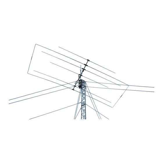
6 E l e m e n t Y a g i 2 0 / 1 5 / 1 0
!!! Q u a l i t y m a d e i n G e r m a n y !!!
Entwicklung, techn. Beratung, Information und Vertrieb / development, techn. consulting, information and distribution:
DF2BO
Thomas Schmenger
Rastatter Straße 37
D-75179 Pforzheim
Tel./Fax: (0049) 07231 / 45 31 53
Email: Info@optibeam.de
computer-designed / computer-optimiert
entwickelt von Funkamateuren für Funkamateure
optimum short-wave antennas
computer-designed / computer-optimized
O B 6 – 3 M
DF4IAR
Christian Römer
Schubertstraße 20
D-76593 Gernsbach
Tel.: (0049) 7224 / 65 68 92
Email: df4iar@t-online.de
Advertisement
Table of Contents

Summary of Contents for OPTIBEAM OB6-3M
- Page 1 Entwicklung, techn. Beratung, Information und Vertrieb / development, techn. consulting, information and distribution: DF2BO DF4IAR Thomas Schmenger Christian Römer Rastatter Straße 37 Schubertstraße 20 D-75179 Pforzheim D-76593 Gernsbach Tel./Fax: (0049) 07231 / 45 31 53 Tel.: (0049) 7224 / 65 68 92 Email: Info@optibeam.de Email: df4iar@t-online.de...
- Page 2 1. Allgemeines Der OB6-3M ist eine hoch effiziente Dreiband-Kurzwellenyagi für die Frequenzbereiche 14, 21 und 28 MHz, der unter Verwendung eines Tuners auch als Kompromiß auf den Frequenzbereichen 18 und 24 MHz verwendet werden kann. OptiBeam-Kurzwellenantennen werden mit modernen Hilfsmitteln rechnergestützt entwickelt und optimiert und durch umfangreiche Praxistests abgeglichen.
- Page 3 2.1 Sortierung des Materials Die Antenne besteht z.T. aus bereits vormontierten Bauteilen. Alle Teile der Antenne sind beschriftet. Zur Beschleunigung und Vereinfachung des Aufbaus ist es zweckmäßig, das Material nach den zugehörigen Frequenzbereichen zu sortieren. 2.2 Zusammensetzung Boom Der Vierkant-Boom besteht aus zwei Teilen, die durch zwei bereits vormontierte Kopplungs-stücke und je Kopplungsstück vier Schrauben miteinander verbunden werden.
- Page 4 Die Enden der gebogenen 12mm Außenrohre des 20m-Bandes stehen sich nach erfolgter Montage 18cm gegenüber. Sie sind durch die Abstandsisolatoren miteinander zu verbinden und werden dadurch stabilisiert. Die Befestigung der Element-Plattformen erfolgt durch zwei Vierkantbügel, die den Boom von der Oberseite her umfassen und vier selbstsichernde Muttern (sh.
- Page 5 3. Anschluß Koaxkabel Die Einspeisung der Antenne erfolgt durch 50-Ohm-Koaxialkabel. Für den Anschluß ist ein Koaxstecker vom Typ PL-259 erforderlich. Der Stecker sollte gegen das Eindringen von Feuchtigkeit abgedichtet werden. Das Kabel ist kurz vor dem Speisepunkt in 5 - 6 Windungen zu einer Drossel mit etwa 20 cm Durchmesser aufzuwickeln.
- Page 6 1. Introduction The OB6-3M is a high performing Triband Antenna for the 14, 21 and 28 MHz amateur radio bands which, by use of a tuner, can also be used on the 18 and 24 MHz WARC bands as a compromize.
- Page 7 2.2 Assembly of boom The square-boom consists of two parts which have to be assembled by the two coupling pieces that are already installed at one side of the boom. For each coupling piece 4 screws are needed. The screws have to be tightened finally not before the parts of the boom really fit to each other perfectly.
- Page 8 The plates are attached to the boom by 2 square brackets which embrace the boom from the top and 4 self securing nuts (see picture page). When tightening the square brackets pay attention that all elements are parallel to each other. The driven elements (from the rear S10, S15, S20) should not be tightened before the installation of the phase line is done (see fig.
- Page 9 3. Connection of coax cable The feeding of the antenna is done by 50 Ohm coax cable. For connection a PL-259 connector is required. The connector should be sealed against water entry. Close to the feed point the cable should be winded to a choke coil with 5 to 6 turns of about 20 cm of diameter.
- Page 11 Boomkopplung vor dem Zusammensetzen zusammengesetzte Boomsegmente Unconnected boom segments showing internal coupling Connected boom segments 20m Moxon-Element Phasenleitungsbereich (Antennen in Rückenlage) 20m Moxon element phase line area (antenna on its back) einzelverbohrte Elementsegmente mit Stufenlöchern für 6 oder 4mm Schrauben Single drilled element section that depicted the drilled step hole for either 6mm or 4mm screws...
- Page 12 Elementhalterung (hier Strahler) mit eingefügtem Mittelsegment (Ober- und Unteransicht) Element holder (here driven element) with inserted middle segment (top and bottom view)
Need help?
Do you have a question about the OB6-3M and is the answer not in the manual?
Questions and answers