Table of Contents
Advertisement
Available languages
Available languages
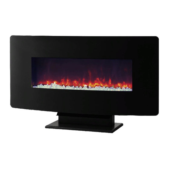
35" Wall mount heater
THIS INSTRUCTION BOOKLET CONTAINS IMPORTANT SAFETY INFORMATION. PLEASE
READ AND KEEP FOR FUTURE REFERENCE.
ESTE FOLLETO DE INSTRUCCION CONTIENE INFORMACION IMPORTANTE DE SEGURIDAD.
POR FAVOR LEA Y GUARDE PARA REFERENCIA FUTURA.
CE LIVRET D'INSTRUCTIONS CONTIENT DES INFORMATIONS IMPORTANTES SUR LA
SÉCURITÉ. S.V.P. LIRE ET CONSERVER POUR RÉFÉRENCE FUTURE.
DO NOT RETURN PRODUCT TO THE STORE. Individual stores do not stock parts.
ALTO
STOP
NO DEVUELVA ESTE PRODUCTO A LA TIENDA. Las tiendas no almacenan partes.
ARRÊT
NE PAS RETOURNER LE PRODUIT AU MAGASIN. Les magasins
individuels ne tiennent pas les pièces en inventaire.
Lot Number / Número de Lote / Numéro de lot: ___________
Date Of Purchase / Fecha de Compra / Date d'achat: ____ / ____ / ____
If a part is missing or damaged, call our toll-free customer service line. We will gladly ship your
replacement parts FREE of charge.
Si faltan partes o piezas,o éstas estàn dañadas, llame gratis al teléfono de servicio al cliente.
Con gusto le enviaeremos las partes sin cargo alguno.
Si une pièce est manquante ou endommagée, appelez sans frais notre ligne du service à la clientèle.
Il nous fera plaisir de vous expédier les pièces de remplacement GRATUITEMENT.
Need Parts or Assistance? / Nesacitas partes o asistancia? / Besoin de pièces ou d'assistance?
or access our website: / o visite nuestra pàgina de internet: / ou visitez notre site Web:
For prompt, reliable service please have your assembly manual ready.
Para obtener servicio rapido y confiable, por favor tenga esta manual a la mano.
Pour obtenir un service rapide et fiable, s.v.p. ayez en main votre manuel d'assemblage.
E35WF
261046
Calefactor de 89 cm
montable en la pared
1-800-489-3351
www.altrafurniture.com
5033096
89 cm a chauffage
montage mural
B34503309600
Español p. 14
Français p. 26
Advertisement
Chapters
Table of Contents

Summary of Contents for ALTRA Flame 5033096
- Page 1 5033096 Calefactor de 89 cm 89 cm a chauffage 35" Wall mount heater montable en la pared montage mural THIS INSTRUCTION BOOKLET CONTAINS IMPORTANT SAFETY INFORMATION. PLEASE READ AND KEEP FOR FUTURE REFERENCE. ESTE FOLLETO DE INSTRUCCION CONTIENE INFORMACION IMPORTANTE DE SEGURIDAD.
-
Page 2: Table Of Contents
Table of Contents Table of Contents ............... Installation - Wall-Mount ........... Safety Information ..............Installation - Table Top............ 9 Warranty ................... Operation............11 Pre-Installation ................Care and Cleaning............13 Safety Information Retain for future reference: Read carefully 16. Always plug heaters directly into a wall outlet/ receptacle. Neveruse with an extension cord or relocatable power tap 1. -
Page 3: Warranty
1 Year Warranty What is Covered The manufacturer warrants that your new electric fireplace is free from manufacturing and material defects for a period of one year from date of purchase, subject to the following conditions and limitations. This electric fireplace must be installed and operated at all times in accordance with the instructions furnished with the product. -
Page 4: Pre-Installation
Pre-installation PLANNING INSTALLATION Before you begin assembly, locate the instructions and hardware. Compare all parts with the Hardware Included and Package Contents lists. Be sure you have all the parts and can identify them. A helping hand is always good. Assemble your fireplace with an adult assistant if possible. -
Page 5: Package Contents
Pre-installation (continued) PACKAGE CONTENTS Part Part Number Description Quantity Part Part Number Description Quantity T5033096010 Electric Firebox T5033096060 Deflector T5033096020 Glass Front T5033096070 Table Top Base T5033096030 Mounting Bracket T5033096080 Remote Control (attached to the Firebox A) T5033096090 Battery T5033096040 Acrylic Crystals T5033096050 Table Top Supports... - Page 6 Pre-installation (continued) TOOLS REQUIRED(NOT INCLUDED) Phillips screwdriver Safety goggles Power drill Stud finder HARDWARE INCLUDED M 5 x 40 ③ ① M4x8 ② M6x 12 Part Part Number Description Quantity TTD0001 Small Screw TTD0002 screw and nut TTD0003 Large Screw...
-
Page 7: Installation - Wall-Mount
Installation - Wall-mount 1. Removing the mounting bracket Using a screwdriver, loosen the two screws that secure the mounting bracket (C) to the top of the electric firebox (A), and remove the mounting bracket (C). 2. Securing the mounting bracket IMPORTANT: This unit is designed to be securely attached to a wall or a fixed structure. - Page 8 Installation - Wall-mount (continued) 3. Hanging the electric firebox Hang the electric firebox (A) on the hooks at the bottom of the mounting bracket (C), and push the top of the electric firebox (A) into the mounting bracket(C). Secure the electric firebox (A) to the mounting bracket (C) by refitting the two small screws which were removed in step 1.
-
Page 9: Installation - Table Top
Installation - Table Top 1. Securing the Table Top Supports securing the table top supports(E) to the Table Top Base(G) with ② four screws and nuts( ) M6 x12 ② ② 2. Attaching the deflector Attach the deflector(F) to the Table Top Supports(E) 3. - Page 10 Installation - table top (continued) 4. Inserting the ember bed Arrange the ember beds (acrylic crystals [D]),along the inset window ledge at the front of the electric firebox (A). 5. Installing the glass front NOTE: This glass front is heavy. It is recommended that you use two people at this stage to prevent damage to the glass front or the electric firebox.
-
Page 11: Operation
Operation USING THE MANUAL AND REMOTE CONTROLS On the top-right side plate of the electric fireplace (A) is the control panel. This panel contains the buttons to properly operate the electric freplace. The buttons on the control panel on the side of the electric freplace (A) and the remote control (H) function in the same way. The remote control has an effective range of up to 13 feet. - Page 12 Operation (continued) USING THE THERMOSTAT CONTROL BUTTON The heat button (3) turns the heater on and off. Display Value Temperature Setting 64°F/18°C With the unit ON, press the control panel heat button (3) for 5 seconds and enter temperature adjustment mode. 66°F/19°C In the adjustment mode, the digital indicator (5) will 68°F/20°C...
-
Page 13: Care And Cleaning
Care And Cleaning IMPORTANT: Always unplug the power cord before cleaning the unit. Allow the unit to cool before cleaning it. Wipe the exterior surface of the electric firebox occasionally with a soft, damp cloth (not dripping wet), and dry the exterior surface before operating. -
Page 14: Tabla De Contenidos
Tabla De Contenidos Tabla de contenidos............14 Instalación - Fijación a pared ..........19 Información de seguridad............14 Instalación - Mueble ............21 Garantía ................15 Operació n................23 Pre-Instalación ..............16 Cuidado y limpieza .............27 Información De Seguridad 16. Siempre conecte los calentadores directamente a una toma de corriente/receptá... -
Page 15: Garantía
Garantía De 1 Año LO QUE ESTÁ CUBIERTO El fabricante garantiza que su nueva chimenea eléctrica estálibre de defectos de fabricación y materiales por un periodo de año a partir de la fecha de compra, sujeto a las siguientes condiciones y limitaciones. Esta chimenea eléctrica debe ser instalada y operada en todo momento de acuerdo con las instrucciones proporcionadas con el producto. - Page 16 ESPECIFICACIONES Modelo no. E35WF(5033096) Dimensiones del Montaje en pared an x pr x al 36 in. x 4.3in. x 17.3 in. (91.5cm x 11 cm x 44cm) Dimensiones como soporte de pie an x pr x al 36 in.
-
Page 17: Pre-Instalación
Pre-instalación (continuación) CONTENIDO DEL PAQUETE Parte Parte Number Descripción Quantity Parte Parte Number Descripción Quantity T5033096010 Calefactor T5033096060 Deflector T5033096020 Cristal frontal T5033096070 Base del calefactor T5033096080 Control remote T5033096030 Soporte de Montaje (conectado al calefactor A) T5033096090 Batería T5033096040 Cristales de acrílico T5033096050 Soportes para mueble... - Page 18 Pre-instalación (continuación) HERRAMIENTAS REQUERIDAS (NO INCLUIDOS) Gafas de seguridad Desarmador Phillips Taladro Detector de viga Herramientas Incluídas ③ M 5 x 40 ① M4x8 ② M6x 12 Parte Parte Number Descripción Cantidad ① TTD0001 Tornillo pequeño ② TTD0002 tornillos y tuercas ③...
-
Page 19: Instalación - Fijación A Pared
Instalación - Fijación A Pared 1. Cómo retirar el soporte de montaje Utilizando un desatornillador, afloje los dos tornillos que unen el soporte de montaje (C) a la parte superior delcalefactor (A), y retire el soporte de montaje (C). 2. Fijación del soporte de montaje IMPORTANTE:Esta unidad es diseñada para sujetar firmemente a una pared o una estructura fija. - Page 20 Instalación - Fijación A Pared (continuación) 3. Cómo colgar el calefactor Cuelgue el calefactor (A) en los ganchos de la parte de abajo del soporte de montaje (C) y empuje la parte dearriba del calefactor (A) al soporte del montaje (C). Fije el calefactor (A) al soporte de montaje (C) reponiendo los dos tornillos pequeñ...
-
Page 21: Instalación - Mueble
Instalación – Mueble 1. Fije los Soportes de la Superficie Fije los soportes de la Superficie (E) a la Base de la Superficie (G) con cuatro tornillos y tuercas(②) M6 x12 ② ② 2. Conecte el deflector Conecte el deflector(F) a los Soportes de la Superficie (E). 3. - Page 22 Instalación - Mueble (continuación) 4. Inserción de la capa de brasas Coloque la capa de brasas (cristales de acrí lico [D], alfé izar en la parte delantera del calefactor (A). a lo largo de la inserción del 5. Instalación del cristal frontal NOTA:El cristal frontal es pesado.
-
Page 23: Operación
Operación USO DEL MANUAL Y CONTROLES REMOTOS El panel de control se encuentra en la placa superior derecha del calefactor (A). Este panel contiene los botones para la correcta operación. Los botones en el panel de control a uno de los lados del calefactor (A) y el control remoto (H) funcionan de la misma manera. El control remoto tiene un alcance efectivo de hasta 4 metros. - Page 24 Operación (continuación) CÓMO UTILIZAR EL BOTÓN DE CONTROL DEL TERMOSTATO El botón de calor (3) apaga y enciende el calentador. Valor en pantalla Posición de temperatura Con el equipo ENCENDIDO, pulse el botón de calor del 64°F/18°C panel de control (3) por 5 segundos y entre a la modalidad de ajuste de temperatura.
-
Page 25: Cuidado Y Limpieza
Cuidado Y Limpieza IMPORTANTE: Desenchufe siempre el cable de alimentación antes de limpiar la unidad. Deje que la unidad se enfríe antes de limpiarla. Limpie la superficie exterior del calefactor de vez en cuando con un pañ o suave y hú medo (que no esté muy mojado), y sequela superficie antes de operar la unidad. -
Page 26: Renseignements De Sécurité
Table Des Matières : Installation - Montage mural ..........Table des matières ..............26 Installation - Sur table............33 Renseignements de sécurité..........26 Instructions de fonctionnement ..........GARANTIE ...............27 Instructions d'entretien............37 Préinstallation ..............28 Renseignements De Sécurité Conserver pour référence ultérieure : lire attentivement 16. - Page 27 Garantie Limitée D’un An CE QUI EST COUVERT Le fabricant garantit que votre nouveau foyer électrique est exempt de défauts de matériau et de fabrication pour une pé riode d’un an àcompter de la date d’achat, sous réserve des conditions et limitations suivantes. Ce foyer électrique doit être installéet fonctionner en tout temps conformément aux instructions fournies avec le produit.
-
Page 28: Préinstallation
Préinstallation PLANIFIER L'INSTALLATION Avant de commencer, ayez sous la main les directives d'installation et les articles de quincaillerie. Sortez toutes les pièces et comparez- les par rapport aux schémas ci-dessous. Assurez vous d'avoir toutes les pièces et de pouvoir les identifier. L'Assemblage de ce produit nécessite deux personnes. - Page 29 Préinstallation (suite) CONTENU DE DE LA BOÎTE Pièce Parte Number Description Quantité Pièce Parte Number Description Quantité T5033096010 Foyer é T5033096060 D flecteur T5033096020 Vitre avant T5033096070 Base pour installation sur table T5033096030 Support de montage (fixé à la boîte à é...
- Page 30 Préinstallation (suite) OUTILS NÉCESSAIRES (NON INCLUS) Lunettes de sécurité Tournevis cruciforme Perceuse Détecteur de montant MATÉRIEL INCLUS ① M4x8 ③ M 5 x 40 ② M6x 12 Pièce Parte Number Description Quantité ① TTD0001 Petite vis ② TTD0002 vis et quatre écrous ③...
-
Page 31: Installation - Montage Mural
Installation - Montage Mural 1. Retirer le support de montage À l'aide d'un tournevis, dévissez les deux vis qui fixent le support de montage (C) au dessus du foyer (A), et retirez le support de montage (C). 2. Fixer le support de montage IMPORTANT :Cette unité... - Page 32 Installation - Montage Mural (continu) 3. Accrocher la boîte à combustion électrique Accrochez la boîte à combustion électrique (A) sur les crochets au bas du support de montage (C), et poussez le haut de la boîte à combustion électrique (A) dans le support de montage (C).
-
Page 33: Installation - Sur Table
Installation – Sur Table 1. Fixer les supports du Dessus de Table Fixez les supports du Dessus de Table (E) à la Base du Dessus ② de Table (G) avec quatre vis et quatre écrous ( M6 x12 ② ② 2 . - Page 34 Installation - Sur Table (continu) 4. Insérer le lit de braises Arrangez les lits de braises (cristaux acrylique [D]),le long du bord de la fenêtre à l'avant de la boîte à combustion électrique (A). 5. Installer la vitre avant REMARQUE : Cette vitre est lourde. Il est recommandé d'avoir 2 personnes pour cette étape pour éviter d'endommager la vitre avant ou la boîte à...
-
Page 35: Instructions De Fonctionnement
Utilisation UTILISER LES COMMANDES MANUELLES ET À DISTANCE Sur la plaque supérieure droite du foyer électrique (A) se trouve le panneau de commande. Ce panneau contient les boutons pour utiliser correctement le foyer électrique. Les boutons du panneau de commande situé sur le côté du foyer électrique (A) et les boutons de la télécommande (H) fonctionnent de la même façon. - Page 36 Utilisation (continu) UTILISER LE BOUTON DE CONTRÔLE DU THERMOSTAT Le bouton du chauffage (3) allume et éteint le chauffage. Valeur affichée Réglage de la température 64°F/18°C Quand l'appareil est allumé , appuyez sur le bouton du chauffage de panneau de commande (3) durant 5 secondes et 66°F/19°C entrez dans le mode d'ajustement de la température.
-
Page 37: Instructions D'entretien
Instructions D'entretien IMPORTANT: Débranchez toujours le fil de courant avant de nettoyer l'appareil. Laissez l'appareil refroidir avant de le nettoyer. Essuyez occasionnellement la surface extérieure de la boîte à combustion électrique avec un linge doux et humide (sans être détrempé), et séchez la surface extérieure avant d'utiliser l'appareil.
Need help?
Do you have a question about the 5033096 and is the answer not in the manual?
Questions and answers