Table of Contents
Advertisement
Original Operating Instructions
APS Series – Outdoor Hybrid Inverter
Table of Contents
Original Operating Instructions
APS Series – Outdoor Hybrid Inverter
WSTECH is a Wind&Sun Technologies and Siemens Joint Venture.
Before starting any work, please read "Original Operating
Instructions" and "Function and Interface Description"!
APS-Series 120 Operating Instructions v320 EN
Advertisement
Table of Contents

Summary of Contents for WSTECH APS Series
- Page 1 Table of Contents Original Operating Instructions APS Series – Outdoor Hybrid Inverter WSTECH is a Wind&Sun Technologies and Siemens Joint Venture. Before starting any work, please read "Original Operating Instructions" and "Function and Interface Description"! APS-Series 120 Operating Instructions v320 EN...
-
Page 2: Table Of Contents
Original Operating Instructions APS Series – Outdoor Hybrid Inverter Table of Contents Table of Contents User Information ..................11 Identification of the Product................12 Scope ......................15 Target Audience ................... 15 General Information ..................16 1.4.1 Related Documents ................16 1.4.2... - Page 3 Storage ......................54 Installation ....................55 Protection of Components ................56 Installation Site ..................... 57 4.2.1 Hole Dimension of the APS Carrier ............61 4.2.2 Surfaces ....................64 4.2.3 Centroid (Geometric Centre) ..............64 4.2.4 Centre of Gravity for APS with Cooling Tower ........65 4.2.5 Maximum permissible Wind Speed ............
- Page 4 Commissioning ..................123 Preparing Commissioning ................125 Starting the Product ..................127 Stopping the Product .................. 127 Operation ....................128 User Interface ..................... 128 Operating Modes ..................128 Resetting VNC Password ................128 Assignment of the Digital Outputs ............... 129 Enable Switch .....................
- Page 5 APU Error Codes ..................138 7.3.1 APU Error Codes 1-4, 44, 89, 100 ............140 7.3.2 APU Error Codes 5-11, 40, 48-52, 79, 84-88, 107 ....... 140 7.3.3 APU Error Codes 16-36, 96-99, 102-105, 108-110 ......140 7.3.4 APU Error Codes 46, 47, 53, 54, 56-59, 92, 93 ........140 7.3.5 APU Error Codes 60, 61 ..............
- Page 6 Figure 1: APS with 1-2 APUs ..................12 Figure 2: APS with 3-4 APUs ..................12 Figure 3: Product identification of APS series ............. 12 Figure 4: Example of a type plate ................13 Figure 5: Example of an option plate ................14 Figure 6: Schematic structure (APS with 1-2 APUs) ............
- Page 7 Original Operating Instructions APS Series – Outdoor Hybrid Inverter List of Figures Figure 36: Exterior view front (APS with 1-2 APUs)............. 61 Figure 37: Hole dimension of the APS carrier (APS with 1-2 APUs) ......61 Figure 38: Exterior view front (APS with 3-4 APUs)............. 62 Figure 39: Hole dimension of the APS carrier (APS with 3-4 APUs) ......
- Page 8 Original Operating Instructions APS Series – Outdoor Hybrid Inverter List of Figures Figure 73: Connection of coded plug connector ............87 Figure 74: Tank cover of water-air heat exchanger ............. 89 Figure 75: Ball valves of cooling system (in position ON) ..........89 Figure 76: Attaching the MV skid to APS ..............
- Page 9 Original Operating Instructions APS Series – Outdoor Hybrid Inverter List of Figures Figure 110: Danger areas (interior view back) ............129 Figure 111: Torque check screwed heat sink ............145 Figure 112: Tank cover of water-air heat exchanger ..........146...
- Page 10 Original Operating Instructions APS Series – Outdoor Hybrid Inverter List of Tables List of Tables Table 1: Naming convention ..................19 Table 2: Allocation of schematic structures ..............27 Table 3: Scope of delivery................... 52 Table 4: Separate package for APS ................52 Table 5: Separate package –...
-
Page 11: User Information
User Information 1 User Information Thank you for purchasing an APS Outdoor Hybrid Inverter. By purchasing this Outdoor Hybrid inverter, you have chosen a high-quality WSTECH product. If you have questions about the application, please contact info@wstech.com. Legal Information All rights reserved. Reproduction, also in extract form, only admissible with approval from manufacturer. -
Page 12: Identification Of The Product
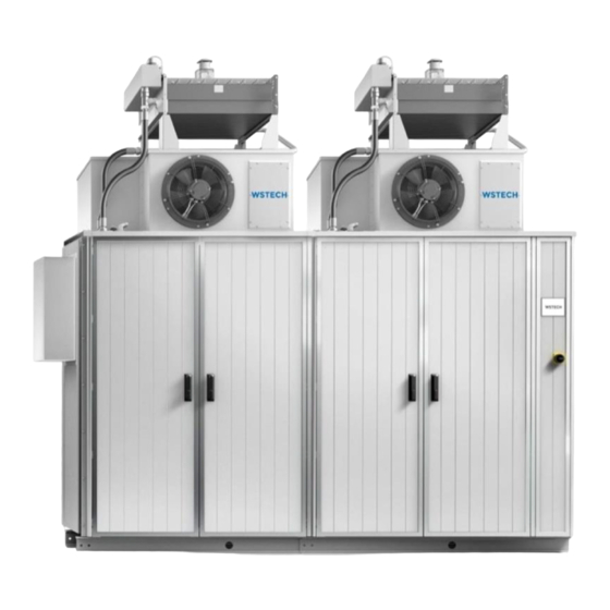
Figure 1 and Figure 2 show the difference of an APS with 1-2 APUs and 3-4 APUs. Figure 1: APS with 1-2 APUs Figure 2: APS with 3-4 APUs The product identification of the APS series is illustrated in Figure 3. Figure 3: Product identification of APS series APS-Series 120 Operating Instructions v320 EN... -
Page 13: Figure 4: Example Of A Type Plate
Original Operating Instructions APS Series – Outdoor Hybrid Inverter User Information The type plates (Figure 4) and option plates (Figure 5) of the APS Outdoor Hybrid Inverter (hereinafter referred to as APS or product) are located at the bottom-right of the front side as well as inside of the control unit). -
Page 14: Figure 5: Example Of An Option Plate
Original Operating Instructions APS Series – Outdoor Hybrid Inverter User Information Figure 5: Example of an option plate APS-Series 120 Operating Instructions v320 EN Page 14 of 213... -
Page 15: Scope
• APS Series (hardware version: 120, wiring diagram version: 3XX) The illustrations used in these operating instructions are reduced to the essentials and may differ from the delivered product. The Manufacturer may change these operating instructions and content therein. -
Page 16: General Information
Original Operating Instructions APS Series – Outdoor Hybrid Inverter User Information General Information These operating instructions provide detailed information regarding specifications, installation procedures, operation, commissioning, troubleshooting, maintenance, decommissioning, technical data, safety procedures and function settings of the product. The operating instructions and the related documents exist only in electronic form. -
Page 17: Symbols
Original Operating Instructions APS Series – Outdoor Hybrid Inverter User Information 1.4.2 Symbols Symbol Description DANGER! Indicates a direct danger situation which will lead to death or severe injury. WARNING! Indicates a possible danger situation which can lead to death or severe injury. - Page 18 Original Operating Instructions APS Series – Outdoor Hybrid Inverter User Information Symbol Description WEEE identification ESD sensitive components Do not step on the marked components. This can damage the components. Escaping of heated air APS-Series 120 Operating Instructions v320 EN...
-
Page 19: Terms And Abbreviations
Original Operating Instructions APS Series – Outdoor Hybrid Inverter User Information 1.4.3 Terms and Abbreviations Table 1: Naming convention Complete designation Designation in the document Apparent Power Master Controller, PLC of APS APMC Apparent power system Apparent power unit Constant current – constant voltage... -
Page 20: Intended Use
Original Operating Instructions APS Series – Outdoor Hybrid Inverter User Information Intended Use The APS is a hybrid inverter that converts the direct current from a DC source into alternating current and feeds it into the grid and vice versa. The product may be used solely in photovoltaic systems, energy storage systems and as STATIC VAR COMPENSTATION (STATCOM). - Page 21 Original Operating Instructions APS Series – Outdoor Hybrid Inverter User Information Should these original operating instructions get lost or are destroyed, the customer must immediately contact the manufacturer to order, at the customer's sole expense, a new operating instructions. APS-Series 120 Operating Instructions v320 EN...
-
Page 22: Safety Instructions
Original Operating Instructions APS Series – Outdoor Hybrid Inverter User Information Safety Instructions DANGER! Danger to life due to disregarding the instructions for action! Disregarding the safety instructions or performing unauthorized actions may lead to serious injury or death. •... - Page 23 Original Operating Instructions APS Series – Outdoor Hybrid Inverter User Information WARNING! Risk of hearing damage due to loud noises of the product! The product generates loud noises during operation. This can cause hearing damage. • Wear hearing protection whenever working on the product.
-
Page 24: Safety Sign On The Product
Original Operating Instructions APS Series – Outdoor Hybrid Inverter User Information Safety Sign on the Product DANGER! Danger to life due to high voltage. Risk of electrical shock from not completely discharged capacitors! • Wait minimum 15 minutes after stopping before working on the product. -
Page 25: Safety Sign On The Packaging
Original Operating Instructions APS Series – Outdoor Hybrid Inverter User Information Safety Sign on the Packaging APS-Series 120 Operating Instructions v320 EN Page 25 of 213... -
Page 26: Cleaning
Original Operating Instructions APS Series – Outdoor Hybrid Inverter User Information Cleaning DANGER! Danger to life due to fire or explosion! There is risk of fire and explosion if inflammable solvents are used. • Use only non-flammable solvents for cleaning. -
Page 27: Description
Original Operating Instructions APS Series – Outdoor Hybrid Inverter Description 2 Description Functional Description In the standard version, the APS is configured as a solar inverter. As a PV inverter, the product can be used in medium- and large-sized PV fields. Such configuration allows for the connection of several generator strings. -
Page 28: Figure 6: Schematic Structure (Aps With 1-2 Apus)
Original Operating Instructions APS Series – Outdoor Hybrid Inverter Description Figure 6: Schematic structure (APS with 1-2 APUs) Pos. Description APUs APS-Series 120 Operating Instructions v320 EN Page 28 of 213... -
Page 29: Figure 7: Schematic Structure (Aps With 3-4 Apus)
Original Operating Instructions APS Series – Outdoor Hybrid Inverter Description Figure 7: Schematic structure (APS with 3-4 APUs) Pos. Description APUs APS-Series 120 Operating Instructions v320 EN Page 29 of 213... -
Page 30: Functional Extensions
Original Operating Instructions APS Series – Outdoor Hybrid Inverter Description Functional Extensions The special applications and their required options are listed below. Energy storage and converter (ES) Installed options: • DC pre-charge circuit for each APU • Operating mode CC-CV for each APU... -
Page 31: Options
Original Operating Instructions APS Series – Outdoor Hybrid Inverter Description Options The following options are available for the APS: • Powerlink (optional Communication Interface) • Network interface (fiber-optic mode) (default: multi-mode): o single-mode • Temperature operating range: o -10 °C … 60 °C (standard) o -25 °C …... - Page 32 Original Operating Instructions APS Series – Outdoor Hybrid Inverter Description The following options are available for two APUs (APU 1-2 and/or APU 3-4): • Insulation monitoring: o Internal o External o Positive grounding o Negative grounding APS-Series 120 Operating Instructions v320 EN...
-
Page 33: Option Seismic Ieee 693
Original Operating Instructions APS Series – Outdoor Hybrid Inverter Description 2.4.1 Option Seismic IEEE 693 NOTICE: Mounting of a cooling tower differs to the standard procedure (Section 4.4). The figures show the stiffening strives and their mounting points in the different Sections. -
Page 34: Option Insulation Monitoring External
Original Operating Instructions APS Series – Outdoor Hybrid Inverter Description For dismounting and mounting the protective covers the next procedure must be performed. Procedure: 1. Loosen the turnbuckle. The turnbuckle is hand-tightened (Figure 11). NOTICE: During mounting ensure the correct order of screw and washer for the screw connection. -
Page 35: Views
Original Operating Instructions APS Series – Outdoor Hybrid Inverter Description Views 2.5.1 Exterior View Figure 13: Exterior view front Figure 14: Exterior view back Pos. Description Type plate and option plate Mandatory sign wear hearing protection Enable switch Touch display... -
Page 36: Figure 15: Dimensioning Dehumidifier Outlet (Bottom View)
Original Operating Instructions APS Series – Outdoor Hybrid Inverter Description Figure 15: Dimensioning dehumidifier outlet (bottom view) Pos. Description Control unit (+C1) APS-Series 120 Operating Instructions v320 EN Page 36 of 213... -
Page 37: Interior View
Original Operating Instructions APS Series – Outdoor Hybrid Inverter Description 2.5.2 Interior View If the protective cover is mounted the customer has access to different components and the DC link measurement points (Figure 16, Figure 17). Figure 16: Interior view front with protective cover Figure 17: Interior view back with protective cover Pos. -
Page 38: Figure 18: Interior View Front
Original Operating Instructions APS Series – Outdoor Hybrid Inverter Description NOTICE: The following figures are shown without protective cover. Figure 18: Interior view front Pos. Description APU 3 APU 4 AC switch Surge arrester (-FA211), AC connection, Fuse (-FC216) Auxiliary transformer (-TA100), behind water pump... -
Page 39: Figure 19: Harmonic Filter (Detail View Of Interior View Front)
Original Operating Instructions APS Series – Outdoor Hybrid Inverter Description Figure 19: Harmonic filter (detail view of interior view front) Pos. Beschreibung Harmonic filter capacitors APS-Series 120 Operating Instructions v320 EN Page 39 of 213... -
Page 40: Figure 20: Interior View Back
Original Operating Instructions APS Series – Outdoor Hybrid Inverter Description Figure 20: Interior view back Pos. Description APU 1 APU 2 DC filter (not used in STATCOM applications) Surge arrester (-FA110.1), DC connection Fuse holder (not used in STATCOM applications) Surge arrester (-FA210.1), DC connection... -
Page 41: Figure 21: Interior View Control Unit
Original Operating Instructions APS Series – Outdoor Hybrid Inverter Description Figure 21: Interior view control unit Pos. Description Apparent Power Master Controller (APMC) Miniature circuit breaker (-FC3), Control voltage Power supply unit 24 V (-TB1) Shock indicator Dehumidifier (-E5) Surge arrester (-FA2) Miniature circuit breaker (-F1), Auxiliary supply Temperature sensor (-BT8.1), Ambient temperature (transport position) -
Page 42: Packaging, Transport, Delivery, Storage
Original Operating Instructions APS Series – Outdoor Hybrid Inverter Packaging, Transport, Delivery, Storage 3 Packaging, Transport, Delivery, Storage Packaging The packaging of the APS and cooling tower depending on the order. In the following possible packaging variants are described. The safety sign on the packaging must be observed (Section 1.8). -
Page 43: Figure 22: Packaging Information - Cooling Tower
Original Operating Instructions APS Series – Outdoor Hybrid Inverter Packaging, Transport, Delivery, Storage 3.1.1.1 Cooling Tower Packaging Information Figure 22 shows the arrangement of components on the pallet. Requirements for packaging: • Transportation shall only be carried out on pallets which have been released by WSTECH GmbH. -
Page 44: Figure 23: Cooling Tower On The Pallet
Original Operating Instructions APS Series – Outdoor Hybrid Inverter Packaging, Transport, Delivery, Storage Figure 23: Cooling tower on the pallet Figure 24: APS with 1-2 APUs on the pallet Figure 25: APS with 3-4 APUs on the pallet APS-Series 120 Operating Instructions v320 EN... -
Page 45: Transport With Wooden Box
Original Operating Instructions APS Series – Outdoor Hybrid Inverter Packaging, Transport, Delivery, Storage 3.1.2 Transport with Wooden Box 3.1.2.1 APS Figure 26 and Figure 27 show the dimensions of the wooden box with pallet. Figure 26: Transport wooden box with pallet (dimensioned) (APS with 1-2 APUs) -
Page 46: Figure 28: Transport Wooden Box With Pallet (Dimensioned) (Cooling Tower)
Original Operating Instructions APS Series – Outdoor Hybrid Inverter Packaging, Transport, Delivery, Storage 3.1.2.2 Cooling Tower Figure 28: Transport wooden box with pallet (dimensioned) (cooling tower) APS-Series 120 Operating Instructions v320 EN Page 46 of 213... -
Page 47: Transport Of Aps Without Cooling Tower
Original Operating Instructions APS Series – Outdoor Hybrid Inverter Packaging, Transport, Delivery, Storage Transport of APS without Cooling Tower WARNING! Danger to life due to falling objects! The product can fall or tip over when transported incorrectly, which may cause damage to the product and result in serious injury or death. -
Page 48: Centre Of Gravity
Original Operating Instructions APS Series – Outdoor Hybrid Inverter Packaging, Transport, Delivery, Storage 3.2.1 Centre of Gravity Observe the eccentric centre of gravity during transport. Figure 29: Centre of gravity symbol The centre of gravity is shown in Figure 30 and Figure 31. All dimensions given in millimetre. -
Page 49: Transport With Hoisting Gear (Aps With 1-2 Apus)
Original Operating Instructions APS Series – Outdoor Hybrid Inverter Packaging, Transport, Delivery, Storage 3.2.2 Transport with Hoisting Gear (APS with 1-2 APUs) NOTICE Damage to the product when using hoisting gear (e.g. forklift)! The product can fall or tip over when transported incorrectly, which may cause damage to the product. -
Page 50: Transport With Crane
Original Operating Instructions APS Series – Outdoor Hybrid Inverter Packaging, Transport, Delivery, Storage 3.2.3 Transport with Crane Transport requirements: • To ensure a safe crane transport the included means for transport (lifting straps, steel shafts and, conveyor beams) must be used. -
Page 51: Container Loading
Original Operating Instructions APS Series – Outdoor Hybrid Inverter Packaging, Transport, Delivery, Storage 3.2.4 Container Loading NOTICE Damage to the product due to incorrectly positioned lashing means! Incorrect lashing leads to damage on the upper sheet metal. In this case, the doors cannot be opened. -
Page 52: Delivery
Original Operating Instructions APS Series – Outdoor Hybrid Inverter Packaging, Transport, Delivery, Storage Delivery 1. Check the shock indicators for transport damage. The shock indicators are inside the control unit (Figure 21) and on the packaging. They indicate an improper transport. -
Page 53: Table 5: Separate Package - Cooling Tower
Original Operating Instructions APS Series – Outdoor Hybrid Inverter Packaging, Transport, Delivery, Storage Table 5: Separate package – cooling tower Required Description Part No. Substitute material material Steel shaft Ø 60 mm x 1600 mm 340820 Cooling fluid hoses with couplings... -
Page 54: Storage
Original Operating Instructions APS Series – Outdoor Hybrid Inverter Packaging, Transport, Delivery, Storage Storage NOTICE Damage to the product due to incorrect storage! Storage of the product with or without packaging, unassembled and in disconnected condition can lead to ingress of moisture and dirt. -
Page 55: Installation
Original Operating Instructions APS Series – Outdoor Hybrid Inverter Installation 4 Installation NOTICE Damage to the product due to lightning! The product has NO lightning protection system. Absence of a lightning protection system can cause damage. • The risk of lightning damage can be reduced by installing a lightning protection system. -
Page 56: Protection Of Components
Original Operating Instructions APS Series – Outdoor Hybrid Inverter Installation Protection of Components Table 8 shows the devices for protecting the components. Table 8: Protection of components (Section +C1) Item Device Component (in Section) designation Miniature circuit breaker Auxiliary supply (Sections +C3 or +C6) -
Page 57: Installation Site
Original Operating Instructions APS Series – Outdoor Hybrid Inverter Installation Installation Site DANGER! Danger to life due to fire or explosion! Unsuitable installation sites can cause fire or explosion, which may cause damage to the product and result in serious injury or death. - Page 58 Original Operating Instructions APS Series – Outdoor Hybrid Inverter Installation NOTICE Damage to the product due to improper foundation! An improper foundation can have influence on stability and IP tightness of the product. • The product must be placed on concrete foundation.
- Page 59 Original Operating Instructions APS Series – Outdoor Hybrid Inverter Installation Environmental conditions: • Ambient temperature range: -10 °C … 60 °C (14 °F … 140 °F) o Option heating -25 °C … 60 °C o Option heating and with additional thermal insulation -40 °C … 60 °C •...
-
Page 60: Figure 35: Schematic View Of The Foundation
Original Operating Instructions APS Series – Outdoor Hybrid Inverter Installation Figure 35: Schematic view of the foundation APS-Series 120 Operating Instructions v320 EN Page 60 of 213... -
Page 61: Hole Dimension Of The Aps Carrier
Original Operating Instructions APS Series – Outdoor Hybrid Inverter Installation 4.2.1 Hole Dimension of the APS Carrier All dimensions given in millimetre. NOTICE: The holes of the MV skid are shown in the customer specific documentation. Figure 36: Exterior view front (APS with 1-2 APUs) Figure 37: Hole dimension of the APS carrier (APS with 1-2 APUs) Pos. -
Page 62: Figure 38: Exterior View Front (Aps With 3-4 Apus)
Original Operating Instructions APS Series – Outdoor Hybrid Inverter Installation Figure 38: Exterior view front (APS with 3-4 APUs) APS-Series 120 Operating Instructions v320 EN Page 62 of 213... -
Page 63: Figure 39: Hole Dimension Of The Aps Carrier (Aps With 3-4 Apus)
Original Operating Instructions APS Series – Outdoor Hybrid Inverter Installation Figure 39: Hole dimension of the APS carrier (APS with 3-4 APUs) Pos. Description Power units (+C3; +C6) Control unit (+C1) DC distributions (+C2; +C5) APS-Series 120 Operating Instructions v320 EN... -
Page 64: Surfaces
Original Operating Instructions APS Series – Outdoor Hybrid Inverter Installation 4.2.2 Surfaces Figure 40: Height and length definition of APS Table 9 shows the surfaces of the APS with 1-2 APUs and 3-4 APUs. Table 9: Surfaces of the APS... -
Page 65: Centre Of Gravity For Aps With Cooling Tower
Original Operating Instructions APS Series – Outdoor Hybrid Inverter Installation 4.2.4 Centre of Gravity for APS with Cooling Tower Figure 43 and Figure 44 show the centre of gravity of the APS with cooling tower. All dimensions given in millimetre. -
Page 66: Cable Entry Areas
Original Operating Instructions APS Series – Outdoor Hybrid Inverter Installation 4.2.6 Cable Entry Areas The customer must perform all cable entries in accordance to IP65 degree of protection. All dimensions given in millimetre. Figure 45: Cable entry areas (APS with 1-2 APUs) -
Page 67: Figure 46: Cable Entry Areas (Aps With 3-4 Apus)
Original Operating Instructions APS Series – Outdoor Hybrid Inverter Installation Figure 46: Cable entry areas (APS with 3-4 APUs) APS-Series 120 Operating Instructions v320 EN Page 67 of 213... -
Page 68: Figure 47: Cable Entry Areas (Aps With 3-4 Apus And Mv Skid)
Original Operating Instructions APS Series – Outdoor Hybrid Inverter Installation Figure 47: Cable entry areas (APS with 3-4 APUs and MV skid) APS-Series 120 Operating Instructions v320 EN Page 68 of 213... -
Page 69: Figure 48: Example Cable Entries Ac Connection
Original Operating Instructions APS Series – Outdoor Hybrid Inverter Installation 4.2.6.1 Cable Entry of the AC Connection The customer must perform the cable entries of the AC connection without cover or delivered cover in accordance to IP65 degree of protection directly in front of the APS. -
Page 70: Figure 49: Cable Entry Dc Connection (Bottom View)
Original Operating Instructions APS Series – Outdoor Hybrid Inverter Installation 4.2.6.2 Cable Entry of the DC Connection Figure 49: Cable entry DC connection (bottom view) Pos. Description Cable entry DC connection (APS with 1-2 APUs) Cable entry DC connection (APS with 3-4 APUs) -
Page 71: Safety Areas
Original Operating Instructions APS Series – Outdoor Hybrid Inverter Installation 4.2.7 Safety Areas All dimensions given in millimetre. Figure 50: Safety area (APS with 1-2 APUs) APS-Series 120 Operating Instructions v320 EN Page 71 of 213... -
Page 72: Figure 51: Safety Area (Aps With 3-4 Apus)
Original Operating Instructions APS Series – Outdoor Hybrid Inverter Installation Figure 51: Safety area (APS with 3-4 APUs) APS-Series 120 Operating Instructions v320 EN Page 72 of 213... -
Page 73: Figure 52: Safety Area (Aps With 3-4 Apus And Mv Skid)
Original Operating Instructions APS Series – Outdoor Hybrid Inverter Installation Figure 52: Safety area (APS with 3-4 APUs and MV skid) APS-Series 120 Operating Instructions v320 EN Page 73 of 213... -
Page 74: Obligatory Activities After Transport
Original Operating Instructions APS Series – Outdoor Hybrid Inverter Installation Obligatory Activities after Transport 4.3.1 Checking the Doors NOTICE Damage to the product due to ingress of moisture and dust! Loosen screw connection of doors and covers, faulty door position, incorrect closing of the doors, damaging of the cabinet as well as its door gaskets and plastic cover profile leads to lower IP code. -
Page 75: Figure 55: Check Door Position
Original Operating Instructions APS Series – Outdoor Hybrid Inverter Installation NOTICE: Figure 53 and Figure 54 show only a part of the screw connections. NOTICE: Each door has 5 door hinges. NOTICE: To check and tighten the middle screw of a door hinge, a special tool is required. -
Page 76: Figure 56: Condition Of Door Gaskets
Original Operating Instructions APS Series – Outdoor Hybrid Inverter Installation 4.3.1.3 Check Condition of Door Gaskets and Screw Connections Figure 56: Condition of door gaskets Figure 57: Check of screw connections Pos. Description Door gaskets Assembled rod’s grips Wheel support Plastic cover profile NOTICE: It is forbidden to modify or remove the plastic cover profile (Pos. -
Page 77: Figure 58: Door Closing Mechanism
Original Operating Instructions APS Series – Outdoor Hybrid Inverter Installation 4.3.1.4 Closing the Doors NOTICE: All doors must be closed according to below procedure. Figure 58: Door closing mechanism Pos. Description Closing points NOTICE: Closing doors without pressure 3 points (below, middle and above) may cause damage to the closing mechanism and consequent unsealing the cabinet and failure to meet the cabinet IP. -
Page 78: Positioning The Door Switches
Original Operating Instructions APS Series – Outdoor Hybrid Inverter Installation 4.3.2 Positioning the Door Switches Required material (not included in scope of delivery): • Screw driver Torx TX 25 Figure 59: Door switch Figure 60: Positioning door switch NOTICE: Each door has a door switch. These must be repositioned after transport. -
Page 79: Cooling Tower
Original Operating Instructions APS Series – Outdoor Hybrid Inverter Installation Cooling Tower NOTICE Damage to the product due to ingress of moisture! Incorrect sealing of the cooling tower leads to leakages. • Surfaces and threaded studs must be clean, dry and free of all traces of grease, oil, moisture and dust. -
Page 80: Figure 61: Service Access To Wet Location (With Cover)
Original Operating Instructions APS Series – Outdoor Hybrid Inverter Installation Figure 61: Service access to wet location (with Figure 62: Service access to dry location (without cover) cover) Figure 63: Cooling tower without top cover (top view) Pos. Description Service access cover (to wet location) -
Page 81: Figure 64: Positioning Of Cooling Tower
Original Operating Instructions APS Series – Outdoor Hybrid Inverter Installation 2. Dismount the service access cover (Figure 61, A). 3. Dismount the service access cover (Figure 62, B). NOTICE: Observe the instructions for processing the assembly paste. 4. Apply the assembly paste on all threaded studs. -
Page 82: Figure 65: Mounting The Outer Area Of The Cooling Tower (Detail View)
Original Operating Instructions APS Series – Outdoor Hybrid Inverter Installation Figure 65: Mounting the outer area of the cooling tower (detail view) Pos. Description Hexagon nut Spring lock washer Bonded sealing Figure 66: Mounting the inner area of the cooling tower (detail view) Pos. -
Page 83: Figure 67: Applying The Cabinet Sealing On The Top Cover
Original Operating Instructions APS Series – Outdoor Hybrid Inverter Installation 4.4.1.1 Applying the Cabinet Sealing NOTICE Damage to the product due to ingress of moisture! Incorrect sealing of the cooling tower leads to leakages. • Ensure that the construction adhesive around the air ducts completely sealed against the cooling tower. -
Page 84: Mounting The Radial Fan
Original Operating Instructions APS Series – Outdoor Hybrid Inverter Installation 4.4.2 Mounting the Radial Fan NOTICE: For transport the radial fan is mounted inside the cabinet. Table 13: Required material for one radial fan Quantity Description Part No. Delivery 6 pcs. -
Page 85: Figure 70: Terminal Strip (-X205.3)
Original Operating Instructions APS Series – Outdoor Hybrid Inverter Installation Procedure: 1. Route the cable through the cable grommet. 2. Bring the radial fan into the correct position (Figure 68). 3. Carefully mount radial fan from the inside (Figure 69), so that the device protrudes out of the cabinet. -
Page 86: Connecting Cooling Tower
Original Operating Instructions APS Series – Outdoor Hybrid Inverter Installation 4.4.3 Connecting Cooling Tower Required material (not included in scope of delivery): • 50mm Open-jaw spanner Procedure: 1. Check positioning of the sealing rings. NOTICE: The sealing ring is on the cone on both sides of the fluid hoses. -
Page 87: Figure 73: Connection Of Coded Plug Connector
Original Operating Instructions APS Series – Outdoor Hybrid Inverter Installation Figure 73: Connection of coded plug connector Pos. Description Plug connector tank cooling fluid level Plug connector fan water-air heat exchanger Plug connector fan air-air heat exchanger Plug connector signal cable fan air-air heat exchanger... -
Page 88: Filling And Draining Cooling System
Original Operating Instructions APS Series – Outdoor Hybrid Inverter Installation 4.4.4 Filling and Draining Cooling System CAUTION! Risk of injury due to spattering cooling fluid! Incorrect installation of cooling fluid hoses leads to leakages. • Avoid skin and eye contact. -
Page 89: Figure 74: Tank Cover Of Water-Air Heat Exchanger
Original Operating Instructions APS Series – Outdoor Hybrid Inverter Installation 4.4.4.1 Filling the Cooling System Figure 74: Tank cover of water-air heat Figure 75: Ball valves of cooling system (in position ON) exchanger Pos. Description Tank cover Ball valve Ball valve Required material: •... - Page 90 Original Operating Instructions APS Series – Outdoor Hybrid Inverter Installation 4.4.4.2 Draining the Cooling System Required material (not included in scope of delivery): • Hose (Ø 20 mm) with sealing nipple and cap nut (M18x1.5) • Suitable vessel (each cooling system contains approximately 45 litres) Procedure: 1.
-
Page 91: Mv Skid (Accessory)
Original Operating Instructions APS Series – Outdoor Hybrid Inverter Installation MV Skid (Accessory) 4.5.1 Mounting MV Skid Required material (part of accessory MV skid): • 8 x M12 hexagon nuts • 8 x M12x45 mm hexagon screws • 16 x washers •... -
Page 92: Sealing Against Water And Dust
Original Operating Instructions APS Series – Outdoor Hybrid Inverter Installation 4.5.2 Sealing against Water and Dust NOTICE: Use a self-sealing strip to protect the product against water and dirt. The cover sealing must be attached after the MV transformer is mounted. -
Page 93: Figure 77: Cover Sealing
Original Operating Instructions APS Series – Outdoor Hybrid Inverter Installation Figure 77: Cover sealing Pos. Description Cover Self-sealing strip Surface to bond MV transformer cover Self-sealing strip 235 mm (twice) Self-sealing strip 665 mm (twice) APS-Series 120 Operating Instructions v320 EN... -
Page 94: Electrical Connection
Original Operating Instructions APS Series – Outdoor Hybrid Inverter Installation Electrical Connection DANGER! Danger to life due to electric shock! An incorrect selection and cable routing can cause damage to property and result in death or serious injury. • Selection and installation of electrical equipment, cable and lines must comply to local rules and requirements. -
Page 95: Interfaces Of The Electrical Connections
Original Operating Instructions APS Series – Outdoor Hybrid Inverter Installation 4.6.1 Interfaces of the Electrical Connections Figure 78: Interfaces of the electrical connections APS-Series 120 Operating Instructions v320 EN Page 95 of 213... -
Page 96: Grounding
Original Operating Instructions APS Series – Outdoor Hybrid Inverter Installation 4.6.2 Grounding DANGER! Life hazard due to electric shock! The product must be grounded at the earthing screw to establish a potential equalization. • Provide earth connection before connecting to the AC/DC power. -
Page 97: Figure 79: Earth Connection
Original Operating Instructions APS Series – Outdoor Hybrid Inverter Installation Figure 79: Earth connection Pos. Description Hexagon nut Spring lock washer Cable lug Washer MV skid carrier Connection cable Protection conductor for equipotential bonding APS carrier Hexagon screw Drill hole... -
Page 98: Ac Connection
Original Operating Instructions APS Series – Outdoor Hybrid Inverter Installation Figure 80: Sectional view of MV skid and APS cable connection Pos. Description Connection cable 4.6.3 AC Connection NOTICE Dimensioning of the AC cables! The ampacity of the AC terminals depends on the APU current. -
Page 99: Table 15: Ampacity Of Ac Terminals (Aps With 1 Apu)
Original Operating Instructions APS Series – Outdoor Hybrid Inverter Installation Table 15: Ampacity of AC terminals (APS with 1 APU) Pos. AC Connection Divide of APS nominal current L1. APU 1 1 times APU current L2. APU 1 1 times APU current L3. -
Page 100: Figure 81: Example Of The Ac Connection
Original Operating Instructions APS Series – Outdoor Hybrid Inverter Installation Required material: • 18 x M12x50 mm hexagon screws • 18 x M12 hexagon nuts • 36 x conical spring washers Procedure: 1. Open doors in Section +C3 or +C6 (Figure 13). -
Page 101: Figure 82: Ac Connection (Aps With 2 Apus)
Original Operating Instructions APS Series – Outdoor Hybrid Inverter Installation Table 19: AC connection AC Connection Remarks Max. quantity of for APUs AC cable L1. APU 1 + 2 AC terminals for APU 1 and APU 2 L2. APU 1 + 2... -
Page 102: Figure 83: Ac Connection (Aps With 3 Apus)
Original Operating Instructions APS Series – Outdoor Hybrid Inverter Installation Figure 83: AC connection (APS with 3 APUs) APS-Series 120 Operating Instructions v320 EN Page 102 of 213... -
Page 103: Figure 84: Ac Connection (Aps With 4 Apus)
Original Operating Instructions APS Series – Outdoor Hybrid Inverter Installation Figure 84: AC connection (APS with 4 APUs) APS-Series 120 Operating Instructions v320 EN Page 103 of 213... -
Page 104: Figure 85: Dimensioning Of The Ac Connection
Original Operating Instructions APS Series – Outdoor Hybrid Inverter Installation Figure 85: Dimensioning of the AC connection APS-Series 120 Operating Instructions v320 EN Page 104 of 213... -
Page 105: Figure 86: Dimensioning Of The Ac Connection (Detail View)
Original Operating Instructions APS Series – Outdoor Hybrid Inverter Installation Figure 86 shows the sectional views B-B and C-C. Figure 86: Dimensioning of the AC connection (detail view) APS-Series 120 Operating Instructions v320 EN Page 105 of 213... -
Page 106: Dc Connection (Versions With 1000 V )
Original Operating Instructions APS Series – Outdoor Hybrid Inverter Installation 4.6.4 DC Connection (Versions with 1000 V and 1500 V WARNING! Danger to life due to uneven distribution of the DC power on the APUs! When the complete DC power is connected on one APU the cooper rails can be damaged. -
Page 107: Figure 87: Dc Connection
Original Operating Instructions APS Series – Outdoor Hybrid Inverter Installation Figure 87: DC connection (1000 V ) (detail view) Pos. Description Safety lock washer Cable lug (not included in scope of delivery) Hexagon nut Hexagon screw (pressed-in) Figure 88: DC connection (1500 V ) (detail view) Pos. -
Page 108: Table 20: Connection On Dc Fuse Holder
Original Operating Instructions APS Series – Outdoor Hybrid Inverter Installation Procedure: 1. Open doors in Sections +C2, +C5 (Figure 14). 2. Dismount the protective covers. 3. Check that all screws of the minus cooper rail and plus copper rail are mechanically secured (Figure 89). -
Page 109: Figure 89: Dc Connection
Original Operating Instructions APS Series – Outdoor Hybrid Inverter Installation Figure 89: DC connection Pos. Description Cable entry grommet Mounting bar (C-profile 30x15 mm) with cable clamps DC (-) connection Minus copper rail DC (+) connection DC fuse holder (breakout sectional view) -
Page 110: Figure 90: 1000 Vdc Fuse Holder Right View
Original Operating Instructions APS Series – Outdoor Hybrid Inverter Installation 4.6.4.1 Dimensions of the Fuse Holders Fuse holder for 1000 V version (All dimensions given in millimetre) Figure 90: 1000 V fuse holder right view Fuse size M10x25 M12x30 Figure 92: 1000 V... -
Page 111: Supply Voltage
Original Operating Instructions APS Series – Outdoor Hybrid Inverter Installation Supply Voltage In the delivery status the APS is supplied via the auxiliary transformer. The supply voltage (optional UPS buffered) feeds the radial fans, cooling tower, control and the option heating. -
Page 112: Figure 95: External Supply By The Customer
Original Operating Instructions APS Series – Outdoor Hybrid Inverter Installation Figure 95: External supply by the customer APS-Series 120 Operating Instructions v320 EN Page 112 of 213... -
Page 113: Figure 96: Supply Voltage For Customer Installation Area
Original Operating Instructions APS Series – Outdoor Hybrid Inverter Installation 4.7.1.2 Supply Voltage for Customer Installation Area Customer connection: • Apparent power: 1 kVA • Voltage: 230 V • Maximum current: 4.35 A NOTICE: The customer installation area and its terminals are in the control unit (Section +C1). - Page 114 Original Operating Instructions APS Series – Outdoor Hybrid Inverter Installation 4.7.1.3 Buffered Supply Voltage via external UPS NOTICE: UPS buffered supply voltage is possible only if a device is supplied via the terminal (-X11) at the same time. If an external UPS is connected the internal control and the customer installation area are supplied both with buffered voltage.
-
Page 115: Figure 97: Buffered Supply Voltage Customer Installation Area And Internal Control
Original Operating Instructions APS Series – Outdoor Hybrid Inverter Installation Figure 97: Buffered supply voltage customer installation area and internal control APS-Series 120 Operating Instructions v320 EN Page 115 of 213... -
Page 116: Data Communication
Original Operating Instructions APS Series – Outdoor Hybrid Inverter Installation Data Communication NOTICE Damage to the product due to overvoltage! Overvoltage can be generated by a lightning, by capacitive or inductive interferences of other electric systems. • Ensure that for data communication only a fibre optic cable must be used. -
Page 117: Communication Interfaces
Original Operating Instructions APS Series – Outdoor Hybrid Inverter Installation 4.8.1 Communication Interfaces Procedure: 1. Open doors in Section +C1. 2. Open corresponding cable ducts 3. Route fiber optic cables for data communication through opening and connect to the required port (Figure 99). -
Page 118: Connecting Of Mv Skid Interfaces
Original Operating Instructions APS Series – Outdoor Hybrid Inverter Installation 4.8.1.1 Feedback of the Enable Switch The feedback of the Enable switch can be queried via the terminals (-X6.1-2). Cable requirements: • Connection lines of the feedback, conductor cross-section 1 mm Procedure: 1. -
Page 119: Figure 100: Connection Of Mv Skid Interfaces When Monitored By The Aps
Original Operating Instructions APS Series – Outdoor Hybrid Inverter Installation Figure 100: Connection of MV skid interfaces when monitored by the APS APS-Series 120 Operating Instructions v320 EN Page 119 of 213... -
Page 120: Mv Skid Not Monitored By The Aps
Original Operating Instructions APS Series – Outdoor Hybrid Inverter Installation 4.9.2 MV Skid not monitored by the APS NOTICE Failure during grid connections due to missing cable bridge and resistor! If the APS used without a MV skid or monitored external, the customer must connect delivered cable bridge and a resistor. -
Page 121: Connection Of The Irradiation/Temperature Sensor (Optional)
Original Operating Instructions APS Series – Outdoor Hybrid Inverter Installation 4.10 Connection of the Irradiation/Temperature Sensor (optional) The optional Si-12-TC-T irradiance sensor must be connected to the surge arresters as shown in Figure 102. Figure 21 shows the position of the surge arresters. -
Page 122: After Installation
Original Operating Instructions APS Series – Outdoor Hybrid Inverter Installation 4.11 After Installation After installation the following items must be checked: • Leave no waste packaging, waste and tools within the product. • No transportation and installation damage occurred. •... -
Page 123: Commissioning
Original Operating Instructions APS Series – Outdoor Hybrid Inverter Commissioning 5 Commissioning DANGER! Life hazard due to electric shock! Missing protective cover in the power unit and DC distribution can cause damage to property or personnel. • Do not touch live parts. - Page 124 Original Operating Instructions APS Series – Outdoor Hybrid Inverter Commissioning NOTICE Damage of measuring device caused due to overvoltage! Performing measurements with the incorrect measuring range can cause damage. • Use only measuring devices with correct measuring range. APS-Series 120 Operating Instructions v320 EN...
-
Page 125: Preparing Commissioning
Original Operating Instructions APS Series – Outdoor Hybrid Inverter Commissioning Preparing Commissioning Requirements: • Conditions for operation must be fulfilled (Section 12.2). • An initial setup via the user interface is necessary before commissioning. Figure 103: Routing temperature sensor Figure 104: Position temperature sensor... -
Page 126: Figure 107: Connecting Current Transformer Plug
Original Operating Instructions APS Series – Outdoor Hybrid Inverter Commissioning Figure 107: Connecting current transformer plug Figure 108: Properly connected current transformer plug (side view) Pos. Description Profile of the plug Profile of the connector Procedure: 1. Lead the temperature sensor (Figure 21) through the cable entry grommet (Section +C1) (Figure 103). -
Page 127: Starting The Product
Original Operating Instructions APS Series – Outdoor Hybrid Inverter Commissioning Starting the Product Procedure: 1. See Function and Interface Description. Stopping the Product Procedure: 1. Set operation mode OFF via the user interface (Function and Interface Description). 2. Open doors in Section +C1 (Figure 13). -
Page 128: Operation
Original Operating Instructions APS Series – Outdoor Hybrid Inverter Operation 6 Operation User Interface The product has the following user interfaces: • Local visualization per touch display • Remote visualization per VNC access • FTP access Access by an upstream control is provided via: •... -
Page 129: Assignment Of The Digital Outputs
Original Operating Instructions APS Series – Outdoor Hybrid Inverter Operation Assignment of the Digital Outputs Table 21 shows the assignment of the Digital Outputs (DO). Table 21: Assignment of DOs Modul Assignment -KF6 APU1/2_test-signal -KF7 APU3/4_test-signal Enable Switch If the Enable switch is switched in position OFF, the AC switches and DC switches are operated automatically in position OFF. -
Page 130: Troubleshooting
Original Operating Instructions APS Series – Outdoor Hybrid Inverter Troubleshooting 7 Troubleshooting DANGER! Life hazard due to high voltage! In case of fault, high voltage may still be present on the product. Touching energized parts leads to death or severe injury. -
Page 131: Aps Error Codes
Original Operating Instructions APS Series – Outdoor Hybrid Inverter Troubleshooting APS Error Codes Table 22: Extract of APS Error Codes Code Error Description Corrective Action APU 1 / 2 cooling fluid low Fill up cooling fluid APU 3 / 4 cooling fluid low... -
Page 132: Aps Error Codes 3, 4
Original Operating Instructions APS Series – Outdoor Hybrid Inverter Troubleshooting 7.1.1 APS Error Codes 3, 4 Corrective action: 1. Check the fluid level (Section 4.4.4). In case of low fluid level, refill the cooling system up to the fluid level. -
Page 133: Aps Error Code 24
Original Operating Instructions APS Series – Outdoor Hybrid Inverter Troubleshooting 7.1.7 APS Error Code 24 NOTICE: For monitoring the MV transformer the customer must connect the feedback contact (Section 4.9). Corrective action: 1. Check if the PT100 is connected correctly or is open. -
Page 134: Aps Error Codes 50
Original Operating Instructions APS Series – Outdoor Hybrid Inverter Troubleshooting 7.1.12 APS Error Codes 50 Corrective action: 1. Check if a HIGH-pulse (+24 V ) is applied at (-KF3) port 14 (DI-07) (Figure 21, Pos. 1). If 0 V is applied, apply a HIGH-pulse (+24 V 7.1.13 APS Error Codes 51... -
Page 135: Aps Warning Codes
Original Operating Instructions APS Series – Outdoor Hybrid Inverter Troubleshooting APS Warning Codes Table 23: Extract of APS Warning Codes Code Warning Description Corrective Action APU 1 / 2 cooling fluid low Fill up cooling fluid APU 3 / 4 cooling fluid low... -
Page 136: Aps Warning Codes 1, 2
Original Operating Instructions APS Series – Outdoor Hybrid Inverter Troubleshooting 7.2.1 APS Warning Codes 1, 2 Corrective action: 1. See Section 7.1.1. 7.2.2 APS Warning Code 5 Corrective action: 1. It is recommended to replace all AC surge arrester modules (-FA2) (Figure 21) if the indication shows a red flag. -
Page 137: Aps Warning Codes 29-32
Original Operating Instructions APS Series – Outdoor Hybrid Inverter Troubleshooting 7.2.5 APS Warning Codes 29-32 Corrective action: 1. See Section 7.1.8. 7.2.6 APS Warning Codes 54-57 Corrective action: 1. See Section 7.1.11 7.2.7 APS Warning Code 58 Corrective action: 1. See Section 7.1.12 7.2.8 APS Warning Code 59... -
Page 138: Apu Error Codes
Original Operating Instructions APS Series – Outdoor Hybrid Inverter Troubleshooting APU Error Codes Table 24: Extract of APU Error Codes Code Error Description Corrective Action Overtemperature IGBT L1 Check cooling Overtemperature IGBT L2 Check cooling Overtemperature IGBT L3 Check cooling... -
Page 139: Table 25: Extract Of Apu Error Codes (Continued)
Original Operating Instructions APS Series – Outdoor Hybrid Inverter Troubleshooting Table 25: Extract of APU Error Codes (continued) Code Error Corrective Action DC switch Check DC switch Enable 24V Check enable switch and door switches Driver version L1 Check power stack... -
Page 140: Apu Error Codes 1-4, 44, 89, 100
Original Operating Instructions APS Series – Outdoor Hybrid Inverter Troubleshooting 7.3.1 APU Error Codes 1-4, 44, 89, 100 Corrective action: 1. Check the fluid level (Section 7.1.1). 2. Start the fan manually via VNC access (Function and Interface Description). 3. Check if the fan is ON. -
Page 141: Maintenance
Original Operating Instructions APS Series – Outdoor Hybrid Inverter Maintenance 8 Maintenance DANGER! Danger to life due to high voltage! After stopping dangerous voltage is present in the product. Touching live parts can result in death or serious injury due to electric shock. -
Page 142: Maintenance Every 12 Month
Original Operating Instructions APS Series – Outdoor Hybrid Inverter Maintenance Procedure: 1. Set operation mode to OFF via the user interface (Function and Interface Description). 2. Open doors in Section +C1 (Figure 13). 3. Switch miniature circuit breaker (-F1) in position 0 to disconnect the supply voltage. -
Page 143: Visual Inspection Of The Interior Area
Original Operating Instructions APS Series – Outdoor Hybrid Inverter Maintenance 8.2.3 Visual Inspection of the Interior Area Maintenance Tasks: 1. Open all doors (Figure 13, Figure 14). 2. Check the interior area for dust and water accumulation as well as any vermin. -
Page 144: Condition Check Of The Cables And Lines
Original Operating Instructions APS Series – Outdoor Hybrid Inverter Maintenance 8.2.6 Condition Check of the Cables and Lines Maintenance Tasks: 1. Open all doors (Figure 13, Figure 14). 2. Check all cables and lines for damage. In case of damage, renew the damaged cables and lines. -
Page 145: Figure 111: Torque Check Screwed Heat Sink
Original Operating Instructions APS Series – Outdoor Hybrid Inverter Maintenance 8.2.8.2 Torque Check NOTICE: Torque check is only required for screwed heat sinks. Required material (not included in scope of delivery): • 8 mm Allen key Figure 111: Torque check screwed heat sink Pos. -
Page 146: Table 28: Dosage Of Glycol
Original Operating Instructions APS Series – Outdoor Hybrid Inverter Maintenance 8.2.8.3 Testing of the Cooling Fluid Figure 112: Tank cover of water-air heat exchanger Pos. Description Tank cover NOTICE: The cooling fluid is a mixture with 50 % glycol / 50 % distilled water. -
Page 147: Maintenance Every 48 Months
Original Operating Instructions APS Series – Outdoor Hybrid Inverter Maintenance Maintenance every 48 Months NOTICE: During each maintenance interval, the following point must be checked. The 12-months maintenance (Section 8.1) must also be performed. Table 29: Maintenance in de-energized condition (every 48 months) -
Page 148: Decommissioning
Original Operating Instructions APS Series – Outdoor Hybrid Inverter Decommissioning 9 Decommissioning Procedure: 1. Stop the product (Section 5.3). 2. Switch off the AC/DC power externally and secure it from being switched on again. 3. Ensure that the product is de-energized. -
Page 149: Disposal
Original Operating Instructions APS Series – Outdoor Hybrid Inverter Disposal 10 Disposal The product contains electrical components, metals and liquids. Final and professional disposal of the product must be executed by the customer under the applicable statutory regulations of the country in which the product is used. Please observe the special regulations for electric and electronic equipment in particular. -
Page 150: Customer Service
Original Operating Instructions APS Series – Outdoor Hybrid Inverter Customer Service 11 Customer Service If you have questions regarding the product, please contact our customer service. Please have the following information ready so we can help as quickly as possible. -
Page 151: Appendix
Original Operating Instructions APS Series – Outdoor Hybrid Inverter Appendix 12 Appendix 12.1 Spare Parts List Table 30: Spare parts list for all products Item Section Article description Part no. designation -FA15.1 Surge arrester 2-pole, 24 Vdc 570016 -FA15.2 Surge arrester 2-pole, 12 Vdc... -
Page 152: Table 31: Additional Spare Parts List (Aps With 1000 Vdc )
Original Operating Instructions APS Series – Outdoor Hybrid Inverter Appendix Table 31: Additional spare parts list (APS with 1000 V Item Section Article description Part No. designation -FA110.1/ +C2/+C5 Surge arrester 570046 -FA210.1 -FC112.X/ -FC212.X +C2/+C5 PV Fuse NH2/250A 500341 -FC113.X/... -
Page 153: Technical Data
Original Operating Instructions APS Series – Outdoor Hybrid Inverter Appendix 12.2 Technical Data The following figures are an abstract of the data sheets. APS-Series 120 Operating Instructions v320 EN Page 153 of 213... - Page 154 Original Operating Instructions APS Series – Outdoor Hybrid Inverter Appendix APS-Series 120 Operating Instructions v320 EN Seite 154 von 213...
- Page 155 Original Operating Instructions APS Series – Outdoor Hybrid Inverter Appendix APS-Series 120 Operating Instructions v320 EN Seite 155 von 213...
- Page 156 Original Operating Instructions APS Series – Outdoor Hybrid Inverter Appendix APS-Series 120 Operating Instructions v320 EN Seite 156 von 213...
- Page 157 Original Operating Instructions APS Series – Outdoor Hybrid Inverter Appendix APS-Series 120 Operating Instructions v320 EN Seite 157 von 213...
- Page 158 Original Operating Instructions APS Series – Outdoor Hybrid Inverter Appendix APS-Series 120 Operating Instructions v320 EN Seite 158 von 213...
- Page 159 Original Operating Instructions APS Series – Outdoor Hybrid Inverter Appendix APS-Series 120 Operating Instructions v320 EN Seite 159 von 213...
- Page 160 Original Operating Instructions APS Series – Outdoor Hybrid Inverter Appendix APS-Series 120 Operating Instructions v320 EN Seite 160 von 213...
- Page 161 Original Operating Instructions APS Series – Outdoor Hybrid Inverter Appendix APS-Series 120 Operating Instructions v320 EN Seite 161 von 213...
- Page 162 Original Operating Instructions APS Series – Outdoor Hybrid Inverter Appendix APS-Series 120 Operating Instructions v320 EN Seite 162 von 213...
- Page 163 Original Operating Instructions APS Series – Outdoor Hybrid Inverter Appendix APS-Series 120 Operating Instructions v320 EN Seite 163 von 213...
- Page 164 Original Operating Instructions APS Series – Outdoor Hybrid Inverter Appendix APS-Series 120 Operating Instructions v320 EN Seite 164 von 213...
- Page 165 Original Operating Instructions APS Series – Outdoor Hybrid Inverter Appendix APS-Series 120 Operating Instructions v320 EN Seite 165 von 213...
- Page 166 Original Operating Instructions APS Series – Outdoor Hybrid Inverter Appendix APS-Series 120 Operating Instructions v320 EN Seite 166 von 213...
- Page 167 Original Operating Instructions APS Series – Outdoor Hybrid Inverter Appendix APS-Series 120 Operating Instructions v320 EN Seite 167 von 213...
- Page 168 Original Operating Instructions APS Series – Outdoor Hybrid Inverter Appendix APS-Series 120 Operating Instructions v320 EN Seite 168 von 213...
- Page 169 Original Operating Instructions APS Series – Outdoor Hybrid Inverter Appendix APS-Series 120 Operating Instructions v320 EN Seite 169 von 213...
- Page 170 Original Operating Instructions APS Series – Outdoor Hybrid Inverter Appendix APS-Series 120 Operating Instructions v320 EN Seite 170 von 213...
- Page 171 Original Operating Instructions APS Series – Outdoor Hybrid Inverter Appendix APS-Series 120 Operating Instructions v320 EN Seite 171 von 213...
- Page 172 Original Operating Instructions APS Series – Outdoor Hybrid Inverter Appendix APS-Series 120 Operating Instructions v320 EN Seite 172 von 213...
- Page 173 Original Operating Instructions APS Series – Outdoor Hybrid Inverter Appendix APS-Series 120 Operating Instructions v320 EN Seite 173 von 213...
- Page 174 Original Operating Instructions APS Series – Outdoor Hybrid Inverter Appendix APS-Series 120 Operating Instructions v320 EN Seite 174 von 213...
- Page 175 Original Operating Instructions APS Series – Outdoor Hybrid Inverter Appendix APS-Series 120 Operating Instructions v320 EN Seite 175 von 213...
- Page 176 Original Operating Instructions APS Series – Outdoor Hybrid Inverter Appendix APS-Series 120 Operating Instructions v320 EN Seite 176 von 213...
- Page 177 Original Operating Instructions APS Series – Outdoor Hybrid Inverter Appendix APS-Series 120 Operating Instructions v320 EN Seite 177 von 213...
- Page 178 Original Operating Instructions APS Series – Outdoor Hybrid Inverter Appendix APS-Series 120 Operating Instructions v320 EN Seite 178 von 213...
- Page 179 Original Operating Instructions APS Series – Outdoor Hybrid Inverter Appendix APS-Series 120 Operating Instructions v320 EN Seite 179 von 213...
- Page 180 Original Operating Instructions APS Series – Outdoor Hybrid Inverter Appendix APS-Series 120 Operating Instructions v320 EN Seite 180 von 213...
- Page 181 Original Operating Instructions APS Series – Outdoor Hybrid Inverter Appendix APS-Series 120 Operating Instructions v320 EN Seite 181 von 213...
- Page 182 Original Operating Instructions APS Series – Outdoor Hybrid Inverter Appendix APS-Series 120 Operating Instructions v320 EN Seite 182 von 213...
- Page 183 Original Operating Instructions APS Series – Outdoor Hybrid Inverter Appendix APS-Series 120 Operating Instructions v320 EN Seite 183 von 213...
- Page 184 Original Operating Instructions APS Series – Outdoor Hybrid Inverter Appendix APS-Series 120 Operating Instructions v320 EN Seite 184 von 213...
- Page 185 Original Operating Instructions APS Series – Outdoor Hybrid Inverter Appendix APS-Series 120 Operating Instructions v320 EN Seite 185 von 213...
- Page 186 Original Operating Instructions APS Series – Outdoor Hybrid Inverter Appendix APS-Series 120 Operating Instructions v320 EN Seite 186 von 213...
- Page 187 Original Operating Instructions APS Series – Outdoor Hybrid Inverter Appendix APS-Series 120 Operating Instructions v320 EN Seite 187 von 213...
- Page 188 Original Operating Instructions APS Series – Outdoor Hybrid Inverter Appendix APS-Series 120 Operating Instructions v320 EN Seite 188 von 213...
- Page 189 Original Operating Instructions APS Series – Outdoor Hybrid Inverter Appendix APS-Series 120 Operating Instructions v320 EN Seite 189 von 213...
- Page 190 Original Operating Instructions APS Series – Outdoor Hybrid Inverter Appendix APS-Series 120 Operating Instructions v320 EN Seite 190 von 213...
- Page 191 Original Operating Instructions APS Series – Outdoor Hybrid Inverter Appendix APS-Series 120 Operating Instructions v320 EN Seite 191 von 213...
- Page 192 Original Operating Instructions APS Series – Outdoor Hybrid Inverter Appendix APS-Series 120 Operating Instructions v320 EN Seite 192 von 213...
- Page 193 Original Operating Instructions APS Series – Outdoor Hybrid Inverter Appendix APS-Series 120 Operating Instructions v320 EN Seite 193 von 213...
- Page 194 Original Operating Instructions APS Series – Outdoor Hybrid Inverter Appendix APS-Series 120 Operating Instructions v320 EN Seite 194 von 213...
- Page 195 Original Operating Instructions APS Series – Outdoor Hybrid Inverter Appendix APS-Series 120 Operating Instructions v320 EN Seite 195 von 213...
- Page 196 Original Operating Instructions APS Series – Outdoor Hybrid Inverter Appendix APS-Series 120 Operating Instructions v320 EN Seite 196 von 213...
- Page 197 Original Operating Instructions APS Series – Outdoor Hybrid Inverter Appendix APS-Series 120 Operating Instructions v320 EN Seite 197 von 213...
- Page 198 Original Operating Instructions APS Series – Outdoor Hybrid Inverter Appendix APS-Series 120 Operating Instructions v320 EN Seite 198 von 213...
- Page 199 Original Operating Instructions APS Series – Outdoor Hybrid Inverter Appendix APS-Series 120 Operating Instructions v320 EN Seite 199 von 213...
- Page 200 Original Operating Instructions APS Series – Outdoor Hybrid Inverter Appendix APS-Series 120 Operating Instructions v320 EN Seite 200 von 213...
- Page 201 Original Operating Instructions APS Series – Outdoor Hybrid Inverter Appendix APS-Series 120 Operating Instructions v320 EN Seite 201 von 213...
- Page 202 Original Operating Instructions APS Series – Outdoor Hybrid Inverter Appendix APS-Series 120 Operating Instructions v320 EN Seite 202 von 213...
- Page 203 Original Operating Instructions APS Series – Outdoor Hybrid Inverter Appendix APS-Series 120 Operating Instructions v320 EN Seite 203 von 213...
- Page 204 Original Operating Instructions APS Series – Outdoor Hybrid Inverter Appendix APS-Series 120 Operating Instructions v320 EN Seite 204 von 213...
- Page 205 Original Operating Instructions APS Series – Outdoor Hybrid Inverter Appendix APS-Series 120 Operating Instructions v320 EN Seite 205 von 213...
- Page 206 Original Operating Instructions APS Series – Outdoor Hybrid Inverter Appendix APS-Series 120 Operating Instructions v320 EN Seite 206 von 213...
- Page 207 Original Operating Instructions APS Series – Outdoor Hybrid Inverter Appendix APS-Series 120 Operating Instructions v320 EN Seite 207 von 213...
- Page 208 Original Operating Instructions APS Series – Outdoor Hybrid Inverter Appendix APS-Series 120 Operating Instructions v320 EN Seite 208 von 213...
-
Page 209: Typical Checklist For Commissioning
Original Operating Instructions APS Series – Outdoor Hybrid Inverter Appendix 12.3 Typical Checklist for Commissioning APS-Series 120 Operating Instructions v320 EN Page 209 of 213... - Page 210 120 Operating Instructions v320 EN Seite...
- Page 211 120 Operating Instructions v320 EN Seite...
-
Page 212: Eu Declaration Of Conformity
12.4 EU Declaration of Conformity 120 Operating Instructions v320 EN Seite...
Need help?
Do you have a question about the APS Series and is the answer not in the manual?
Questions and answers