
Related Manuals for SIAD ESA Pyronics ESTRO-PO E7014P

Summary of Contents for SIAD ESA Pyronics ESTRO-PO E7014P
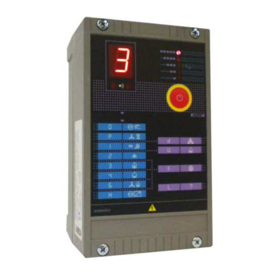
- Page 1 lectronics Permanent Operation Microprocessor Burner Control ESA ESTRO-PO (E7014P rev. 02 - 03/05/2017)
-
Page 2: General Warnings
ESA ESTRO - E7014P rev. 02 - 03/05/17 GENERAL WARNINGS: GENERAL NOTES: ¾ All installation, maintenance, ignition and setting must ¾ In accordance to the internal policy of constant quali- ¾ ¾ ty improvement, ESA-PYRONICS reserves the right to be performed by qualified staff, respecting the norms modify the technical characteristics of the present docu- present at the time and place of the installation. - Page 3 ESA ESTRO - E7014P rev. 02 - 03/05/17 ESA ESTRO is a microprocessor operated flame control device that controls gas and oil fired burners for conti- nuous operation. This device safely controls one or two stage burners (pilot and main), combustion air, and is able to detect the flame signal via ionization sensors (electrodes) or UV radiation (UV-scan), continuously per- forming a periodic check of the flame sensor.
-
Page 4: Inputs And Outputs
ESA ESTRO - E7014P rev. 02 - 03/05/17 CHARACTERISTICS INPUTS AND OUTPUTS: ¾ Voltage to the flame detection probe: max 300 Vac ¾ ¾ Minimum ionization current: 2,4 µA ± 0,3 µA ¾ ¾ Current limits to the probe: 1 mA ¾... - Page 5 ESA ESTRO - E7014P rev. 02 - 03/05/17 DESCRIPTION ESA ESTRO is a microprocessor flame control device applications in which the burners remain running for more equipped with inputs and outputs for controlling and than 24 hours. The instrument has four different versions: supervising burners with permanent functioning, fit for ¾...
- Page 6 ESA ESTRO - E7014P rev. 02 - 03/05/17 ¾ ESA ESTRO-Q: to be used for single stage burners in which control is done via serial line. ¾ IGNITION REMOTE TRANSFORMER CONTROL ESTRO GAS VALVE FLAME SIGNAL D7014PI04 The ESA ESTRO-A, B and C versions also have a digital hour or shut down every 24 hours for non permanent configurable input and output, in particular the digital operation with UV-2.
- Page 7 ESA ESTRO - E7014P rev. 02 - 03/05/17 internal relay protection fuse that blows only in case of devices or specific serial communication can be applied malfunctioning of the first. ESA ESTRO is supplied in a to all the versions. The installation of the expansion cards robust case in thermoset material, predisposed for the precludes the possibility of mounting the ignition transfor- housing of the ignition transformer and for the outputs of...
- Page 8 ESA ESTRO - E7014P rev. 02 - 03/05/17 DISPLAY AND LOCAL BUTTON SECTION DISPLAY ESA ESTRO displays different codes to indicate the flame control functioning and lockout statuses. Fixed symbols indicate normal operating conditions or certain non resettable faults, whilst lock or resettable fault con- ditions are indicated by flashing symbols.
- Page 9 ESA ESTRO - E7014P rev. 02 - 03/05/17 DISPLAY STATUS DESCRIPTION Regime phase for ESA ESTRO-B with only 2nd stage burner on. The instru- FIXED ment intercepts the 1st stage solenoid valve. This phase occurs only when the “1st stage gas outlet type” parameter is programmed on “Interrupted”. Regime phase with air valve on.
- Page 10 ESA ESTRO - E7014P rev. 02 - 03/05/17 DISPLAY STATUS DESCRIPTION Lockout due to the extended absence of serial commands by the remote super- FLASHING visor, for a longer period of time than the period programmed in the “Communication timeout” parameter. Malfunctioning is due to the presence of the air pressure switch signal before the instrument has activated the combustion blower.
- Page 11 ESA ESTRO - E7014P rev. 02 - 03/05/17 DISPLAY STATUS DESCRIPTION Lockout due to an error in the internal memory reading. The failure can be tem- porary or final. The causes can be found in the incorrect connection to ground of the instrument or of the connected ignition devices, in the missing suppres- FLASHING sion filter in the ignition electrode connector, or else in the strong electromagne-...
- Page 12 ESA ESTRO - E7014P rev. 02 - 03/05/17 Configuration DISPLAY STATUS DESCRIPTION Programming phase from serial input via the special configuration software. FIXED During this phase it is not possible to carry out any other operation. Programming phase from infrared input via the special programmer. Fase di FIXED programmazione da ingresso infrarosso tramite l’apposito programmatore.
- Page 13 ESA ESTRO - E7014P rev. 02 - 03/05/17 FUNCTIONING BURNER IGNITION CYCLE ESA ESTRO is a configurable device for burner control that, depending on the set parameters, can assume diffe- The following diagram indicates an ignition cycle when rent behaviour or determine different actions (see the EXP-2 expansion card has been installed to control a Configuration parameters).
-
Page 14: Auto Start
ESA ESTRO - E7014P rev. 02 - 03/05/17 BURNER IGNITION CYCLE The following diagram indicates an ignition cycle of ESA ESTRO-B version without EXP-2 expansion card with first gas stage output interrupted. COMPLETE CYCLE D7014PI10 IGNITION BEHAVIOUR The following diagrams indicate the behaviour at instrument powering according to the “Cycle start” parameter if con- figured on “Autostart”... - Page 15 ESA ESTRO - E7014P rev. 02 - 03/05/17 STANDBY In the following diagram we have indicated the ESA ESTRO-B ignition cycle without EXP-2 expansion card. STAND-BY D7014PI12 ILLEGAL FLAME The following diagram indicates the behaviour in the presence of an illegal flame at burner ignition or shut down IN FAULT “d”...
-
Page 16: Failed Ignition
ESA ESTRO - E7014P rev. 02 - 03/05/17 FAILED IGNITION The following diagram indicates the behaviour in case of 1st gas stage ignition failure. IN FAULT “U” D7014P14 FLAME SIGNAL LOSS The following diagram indicates the behaviour if the flame signal is lost with burner in regime phase and with the “Behaviour at flame loss”... -
Page 17: Configuration Parameters
ESA ESTRO - E7014P rev. 02 - 03/05/17 CONFIGURATION PARAMETERS The software installed on the pc instead, communicates The configuration defines the ESA ESTRO functioning via the ECS serial interface and allows all the non bloc- mode, adapting it to the needs of the plant. Certain confi- ked parameters to be altered. - Page 18 ESA ESTRO - E7014P rev. 02 - 03/05/17 PARAMETER VALUE DESCRIPTION N° NAME The instrument performs burner reignition (excluding prepurge) after the flame signal has disappeared. When burner ignition has taken place cor- Respark rectly, at the next flame extinction, the instrument performs another rei- gnition sequence.
- Page 19 ESA ESTRO - E7014P rev. 02 - 03/05/17 PARAMETER VALUE DESCRIPTION N° NAME The instrument maintains the same behaviour as when “Discontinue Discontinue delayed 0 sec” is selected, with the difference being that from the valve closing command, it waits for 5 seconds before moving onto burner igni- delayed 5 sec tion, giving the valve time to close.
- Page 20 ESA ESTRO - E7014P rev. 02 - 03/05/17 PARAMETER VALUE DESCRIPTION N° NAME The digital output indicates that the instrument is in lockout status, Stop / fault manual stop or waiting after power on (flashing display). The output is not activated during auto diagnosis.
- Page 21 ESA ESTRO - E7014P rev. 02 - 03/05/17 PARAMETER VALUE DESCRIPTION N° NAME The instrument does not control the expansion cards. This configuration Inhibited is needed when the expansion cards are not installed or if the EXP-3 expansion is present. EXP Installed The instrument activates the expansion card control.
- Page 22 Locked parameters PARAMETER VALUE DESCRIPTION N° NAME First safety time for ignition of the first gas stage (see table of allowed 1° safety time 1 ÷ 25 sec times). The 1st gas stage burner is kept running even after the ignition of the 2nd gas stage, until both are shut down at the same time.This configu- ration is valid for the single stage versions (ESTRO A2, C2 and Q2), or Intermittent...
- Page 23 ESA ESTRO - E7014P rev. 02 - 03/05/17 PARAMETER VALUE DESCRIPTION N° NAME The instrument never activates the high temperature function even after Inhibited the specific command from the digital input. The instrument activates the high temperature function with the sole function of flame bypass for the time in which the specific digital input command is present.
- Page 24 ESA ESTRO - E7014P rev. 02 - 03/05/17 If values not allowed by the EN298 but only by the EN746- In the following table the maximum allowed time limits 2 are set, only the reference norm for which ESTRO is have been indicated.
-
Page 25: Installation
ESA ESTRO - E7014P rev. 02 - 03/05/17 INSTALLATION 9 - The laying out of the flame signal cables must be For correct installation respect the following instructions: separated from power cables and other cables. The use of multi-core cables is not allowed, nor the use of shiel- 1 - Avoid placing ESA ESTRO near intense magnetic or ded cables. - Page 26 ESA ESTRO - E7014P rev. 02 - 03/05/17 WARNINGS ¾ If the digital input assumes the function of FSL for pur- ¾ ging, or FSH for ignition or air pressure, the power sup- ply phase of the sensor must come from the digital out- put that will be configured for this function.
- Page 27 ESA ESTRO - E7014P rev. 02 - 03/05/17 ESA ESTRO-A CONNECTIONS D7014PI16 Pos. Description Pos. Description ECS serial communication Digital input Power supply UV-2 probe flame detection Safety stop Flame detection with dedicated electrode Digital output Unirod flame detection Terminal connectors Pos.
- Page 28 ESA ESTRO - E7014P rev. 02 - 03/05/17 ESA ESTRO-B CONNECTIONS D7014PI17 Pos. Description Pos. Description ECS serial communication Digital input Power supply UV-2 probe flame detection Safety stop Flame detection with dedicated electrode Digital output Unirod flame detection Terminal connectors Pos.
- Page 29 ESA ESTRO - E7014P rev. 02 - 03/05/17 ESA ESTRO-C CONNECTIONS D7014PI18 Pos. Description Pos. Description ECS serial communication Digital input Power supply UV-2 probe flame detection Safety stop Flame detection with dedicated electrode Digital output Unirod flame detection Terminal connectors Pos.
- Page 30 ESA ESTRO - E7014P rev. 02 - 03/05/17 ESA ESTRO-Q CONNECTIONS D7014PI19 Pos. Description Pos. Description ECS serial communication UV-2 probe flame detection Power supply Flame detection with dedicated electrode Safety stop Unirod flame detection Terminal connectors Pos. Description Pos. Description Power supply phase 1st gas stage solenoid valve neutral...
- Page 31 ESA ESTRO - E7014P rev. 02 - 03/05/17 ESA EXP-2 EXPANSION CONNECTIONS D7014PI20 Pos. Description Pos. Description ECS serial communication Air regulation valve limit switch or air flow switch External temperature regulator Air pressure switch and thermostat input Air regulation valve Combustion blower or air valve Terminal connectors Pos.
-
Page 32: Overall Dimensions
ESA ESTRO - E7014P rev. 02 - 03/05/17 OVERALL DIMENSIONS Fixing holes 21.5 18.5 18.5 21.5 18.5 18.5 18.5 22.5 base front internal base view D7014P21 Pos. Elements Preformed holes Diameter mm Cable Fastening connectins for transformer PG11 - M20x1,5 Not used 2-3-4-5-12 PG9 - M16x1,5... -
Page 33: Ordering Code
ESA ESTRO - E7014P rev. 02 - 03/05/17 ORDERING CODE ESA ESTRO MODEL BURNER FUNCTIONING MODE ESTRO - A Not permanent (stop every 24h) ESTRO - B Permanent with detection rod ESTRO - C Permanent with UV and shutter ESTRO - Q AIR FLOW CONTROL TYPE CYCLE START Continue or not present... - Page 34 ESA ESTRO - E7014P rev. 02 - 03/05/17 ORDERING CODE COMMUNICATION BAUDRATE AUTOMATIC IGNITION TRIAL 4800 Inhibited 9600 1 - 9 from 1 to 9 for generic lockout 19200 A - E from 1 to 5 recycle for U lockout 38400 F - L 1 - 5 re-ignition for U Lockout...
Need help?
Do you have a question about the ESA Pyronics ESTRO-PO E7014P and is the answer not in the manual?
Questions and answers