
Summary of Contents for ADWEL DRM-100
- Page 1 User Manual Model DRM-100 Digital Resistance Meter ADWEL International Limited an IRIS Power Company...
- Page 2 Copyright © 2008 ADWEL International Ltd. Copyright in this document is owned by ADWEL International Limited except for information supplied by other parties. No reproduction of the whole or any part is to be made without the authority of ADWEL International Limited ReporteR™...
-
Page 3: Table Of Contents
Introduction ................1 Application.................. 1 Features..................1 Options and Accessories ............. 3 DRM-100 accessories ..............3 Getting to Know the DRM-100........... 4 Front Panel Components............. 4 Power Entry Module with Main Switch........4 Grounding/Earth Terminal ............5 LCD Screen................. 5 Buttons .................. - Page 4 Table of Contents Warning messages..............14 Measuring with the DRM-100 ..........17 Preparation ................17 Locating the DRM-100 ............. 17 Setting Input Voltage ..............17 Connecting to Device..............18 Starting the DRM-100............... 19 Operation Sequence ..............20 Select the Test Current (I=SET)..........20 Select the Measurement Time (t=SET)........
-
Page 5: Safety Warnings
Safety Warnings Safety Warnings Comply with all equipment grounding instructions to avoid dangerous electrical shocks. Only properly trained personnel should use the DRM-100. Safety is the responsibility of the user. 1. Read all safety and operating instructions before operating the equipment. -
Page 6: High Voltage Safety Precautions
Safety Warnings High Voltage Safety Precautions The DRM-100 test set and any device under the test to which it is connected are possible sources of high-voltage electrical energy. Anyone using the test set must take all practical safety precautions to prevent contact with energized parts of the equipment and related circuits. -
Page 7: Built-In Safety Precautions
Emergency button which activation interrupts all output voltages. Power Source The DRM-100 operates from a single-phase power source. It requires a two-pole, three terminal, live, neutral, and ground type connector. The voltage to ground from the live pole of the power source must not exceed the maximum rated operating voltage and can not be changed by user. - Page 8 Safety Warnings Before plugging in the three-wire power cord, make sure the receptacle is properly wired and has a ground contact. Do not bypass the grounding connection. Any interruption of the grounding connection can create an electric shock hazard. Page viii...
-
Page 9: Customer Service
Customer Service Customer Service If you have technical questions on the DRM-100 test set or software, first refer to this User Manual. Contact Information If this manual does not answer your questions, contact ADWEL International Ltd. for technical support at: North America office: •... -
Page 10: Introduction
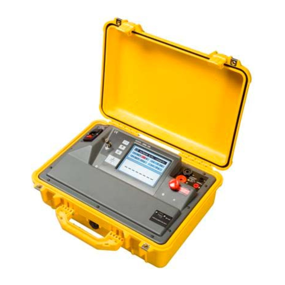
Introduction Chapter Introduction The DRM-100 (Digital Resistance Meter) is used to measure resistance of contacts on de-energized devices such as circuit breakers, switches and bus bars as found in energized high-voltage substations. Application The DRM-100 instrument makes a 4 terminal measurement by passing DC current through the unknown resistance. - Page 11 • The DRM-100 instrument is specifically designed for rough usage and to function reliably in energized EHV substations where high electrical and magnetic fields are frequently present.
-
Page 12: Options And Accessories
Chapter 1 — Introduction Options and Accessories DRM-100 accessories The DRM-100 comes with these standard accessories: • Current Test Leads • Potential Test Leads • Ground lead • Main input power cord (suitable for location) • DRM-100 instrument • User Manual (this document) The optional accessories: •... -
Page 13: Getting To Know The Drm-100
Getting to Know the DRM-100 This chapter describes the various features, tools, and screens of the DRM-100, and how to navigate the system. Front Panel Components Power Entry Module with Main Switch Power Entry Module is located on the top left corner of front panel. -
Page 14: Grounding/Earth Terminal
Chapter 2 — Getting to Know the DRM-100 240VAC 50/60Hz, without need for adjustment. Do not cover Power Entry Module with test leads or any other object and keep it accessible. Grounding/Earth Terminal Metal ground/earth binding post is on the right side of Entry Module for grounding/earth the equipment under the test. -
Page 15: Current Receptacles
Chapter 2 — Getting to Know the DRM-100 Item Description Down Arrow button is used to decrement value of Down selected field of current or time. The current can be Arrow decremented in steps of 10A. The time can be button decremented from in steps of 1 second. -
Page 16: Emergency Stop Button
Chapter 2 — Getting to Know the DRM-100 Emergency Stop Button The large, red, emergency stop, mushroom button is located below the current output and voltage input receptacles. It cuts off the output DC test current immediately (not the instrument main power supply). It is marked with red highlighted text EMERGENCY STOP. -
Page 17: Graphical User Interface
Main page. The contents of these pages are described below. Startup Screen On start up, a window appears with the ADWEL logo, the instrument name, serial number and firmware software version. The start up screen also shows ADWEL’s Address, Telephone and Fax number. -
Page 18: Main Screen
Chapter 2 — Getting to Know the DRM-100 Main Screen Main screen is divided into two areas: 1. Top area is reserved for messages about instrument status, current selection, test duration selection, measured current and count-down timer. 2. Bottom area is reserved to show the bright and easy-to-read 41/2 digit measured resistance. -
Page 19: Continuous Resistance Test
Chapter 2 — Getting to Know the DRM-100 The DRM-100 measures resistance in 3 ranges, which are auto-selected depending on the test current and discovered resistance. The ranges are: 0 µΩ to 1999.9 µΩ for currents from 10 to 100A 0 mΩ... -
Page 20: Current Versus Resistance Ranges
Chapter 2 — Getting to Know the DRM-100 This mode can be used for troubleshooting equipment under test. Current versus Resistance Ranges The maximum voltage that can be measured on the DRM- 100 voltage inputs is slightly over 2V, and it is this that limits the maximum resistance value that may be read. -
Page 21: Prompt Messages
Chapter 2 — Getting to Know the DRM-100 Prompt Messages The current status of the instrument is shown with the appropriate icon followed by a message. There are two types of messages: • Status messages • Warning messages Status messages Status messages describe current status or remind the user about next expected action. - Page 22 Chapter 2 — Getting to Know the DRM-100 checks for any DC voltages generated by galvanic or thermo-electric action between the specimen and the test leads and subtracts this value from the final calculation. – This message is present during <Start>...
-
Page 23: Warning Messages
Chapter 2 — Getting to Know the DRM-100 Warning messages Warning messages describe irregular states of the instrument. They are in white letters on red background. – This message appears if Emergency Activated emergency button has been pressed. Any test in progress will be interrupted and the output current will drop to zero. - Page 24 Chapter 2 — Getting to Know the DRM-100 – This message appears if current test No Current Flow leads are not connected before starting the test of if they are disconnected during the test. The user should connect the current test leads and restart the test.
- Page 25 Chapter 2 — Getting to Know the DRM-100 Page 16...
-
Page 26: Measuring With The Drm-100
• Protect front panel from moisture (rain). Setting Input Voltage The DRM-100 has a universal power supply. Before connecting the DRM-100, ensure the source voltage is within the specified range of 90 V to 265 V -50/60 Hz. Page 17... -
Page 27: Connecting To Device
Check that voltage levels are safe before making connections. Although the DRM-100 can withstand up to 1000 VAC of induced voltage on its input terminals, for operating personnel, it is advisable that one side of the device under test be grounded and that the device contacts remain closed throughout the test. -
Page 28: Starting The Drm-100
Starting the DRM-100 Turn on the power switch. A welcome window appears with the DRM-100 logo. It also displays the company address details along with the instrument serial number. After the welcome screen clears the fields I = SET and t =... -
Page 29: Operation Sequence
Chapter 3 — Measuring with the DRM-100 Operation Sequence Select the Test Current (I=SET) The test current can be selected in range between 10 to 100A in 10A steps. The measurement time can be setup from 10 to 60 seconds in 1 sec steps. The user can select the test current value using the up and down arrow buttons. -
Page 30: Testing Procedures
Make sure the input switch is OFF. Connect the current leads to the current output sockets on the DRM-100 and connect the large alligator clamps to the terminals of the EUT. Connect the potential leads to the voltage input sockets on the DRM-100 and connect the small alligator clamps to the same terminals of the EUT. -
Page 31: Trouble-Shooting Mode
Chapter 3 — Measuring with the DRM-100 Press the START/STOP test start button. The DRM-100 will ramp the current up to the selected test current in 2-3 seconds, then hold the current, then ramp the current back to zero on 2-3 seconds. The total time will be the time set. - Page 32 Use the up/down arrows to adjust the time to infinity (∞) symbol. Press the START/STOP test start button. The DRM-100 will ramp up the current to the selected test current in 2-3 seconds, and then hold the current, until the operator presses the START/STOP button again.
-
Page 33: Technical Specifications
Technical Specification Appendix Technical Specifications Item Description Power Input 85 to 265VAC, 50/60Hz, 800VA max., CAT II Fuse Rating 8A 250VAC, Type T Test Current From 10 to 100 A in 10A steps Ripple < 0.5% Test Current - Permanent Test Time From 10s to 60s in 1s steps (10-100A) Infinite test time at 20A... - Page 34 Appendix A - Technical Specification Item Description Test Leads Standard current leads: 20’ (6m), 4 awg Optional current leads: 30’ (9m), 4 awg 40’ (12m), 4 awg (Maximum 15 mΩ at 100A) 50’ (15m), 2 awg 65’ (20m), 2 awg (Maximum 15 mΩ...
-
Page 35: Ce Declaration Of Conformity
Certificate Appendix CE Declaration of Conformity Page 26... - Page 36 Appendix B - Certificate ADWEL International Ltd. Manufacturer’s Name: 3110 American Drive Manufacturer’s Address: Mississauga ON, L4V 1T2 CANADA The manufacturer hereby declares that the product Digital Resistance Meter Product Name: DRM-100 Model Number: Production Options: Conforms to the following Directives through compliance to...
-
Page 37: Index
CE declaration of Conformity ....26 Connecting to Device..18 Continuous Resistance Getting to Know the Test ......10 DRM-100 ....4 Conventional Mode..21 Graphical User Interface . 8 Current Receptacles ..6 Grounding/Earth Terminal Current versus Resistance ........5 Ranges ...... - Page 38 Kelvin measurement method ......1 Safety built-in safety LCD Screen..... 5 precautions ... vii Location the DRM-100 . 17 high-voltage safety ..vi power source safety .. vii safety symbols .... v safety warnings... v Main Power Switch..4 Select the Measurement Main Screen ....
- Page 39 Appendix C — Index Up Arrow button ..... 5 Warning messages .. 12, 14 Weight ......25 Voltage Receptacles..6 Page 30...
Need help?
Do you have a question about the DRM-100 and is the answer not in the manual?
Questions and answers